
Designing of the Electromechanical Drive for Automated Hot Plate Welder Using Load Optimization with Genetic Algorithm


Abstract
:1. Introduction
1.1. The Source of the Problem
- Specifying the workload which acts on the executive mechanisms;
- Analysis of the structure of the drive unit to obtain a mathematical model of the connections between executive mechanisms and drive systems, considering entire loads and forces. To do this in a proper way, there is a necessity to perform the analysis of the load state of the mechanisms, using basic principles of mechanics, including the strength of the materials for particular parts;
- Estimation of the power consumption based on the workload of the drive system;
- Possible optimization of the power transmission system to obtain effective work parameters with low energy consumption.
1.2. Current State of Knowledge
- The research work which has been undertaken so far, is mainly connected with the butt welding of thermoplastics with relatively high rigidity at the standard environment temperature (polyamide, polycarbonate, polyethylene, and polypropylene);
- Analyzed cases of butt welding mostly concern elements with a complex cross-sectional shape and as a result, their susceptibility to buckling is low.
- Building the mathematical model based on the technological parameters of the hot plate welding process using, for example, experimental data;
- Calculation of the gained model using the genetic algorithm to obtain the effective technological parameters for the purpose of estimating the minimal workload of the drive system;
- Consequently, designing the electromechanical drive system of the automated hot plate welder.
2. The Solution of the Automated Hot Plate Welding Process
2.1. The Essence of Making the Butt Joints of the Round Belt
- Belt preparation that consists of unwinding the belt from the spool, measurement, cutting to the proper length, and placing the cut belt in the appropriate mechanism, which makes it possible to conduct proper manipulation that allows joining execution;
- Conducting the proper welding operation.
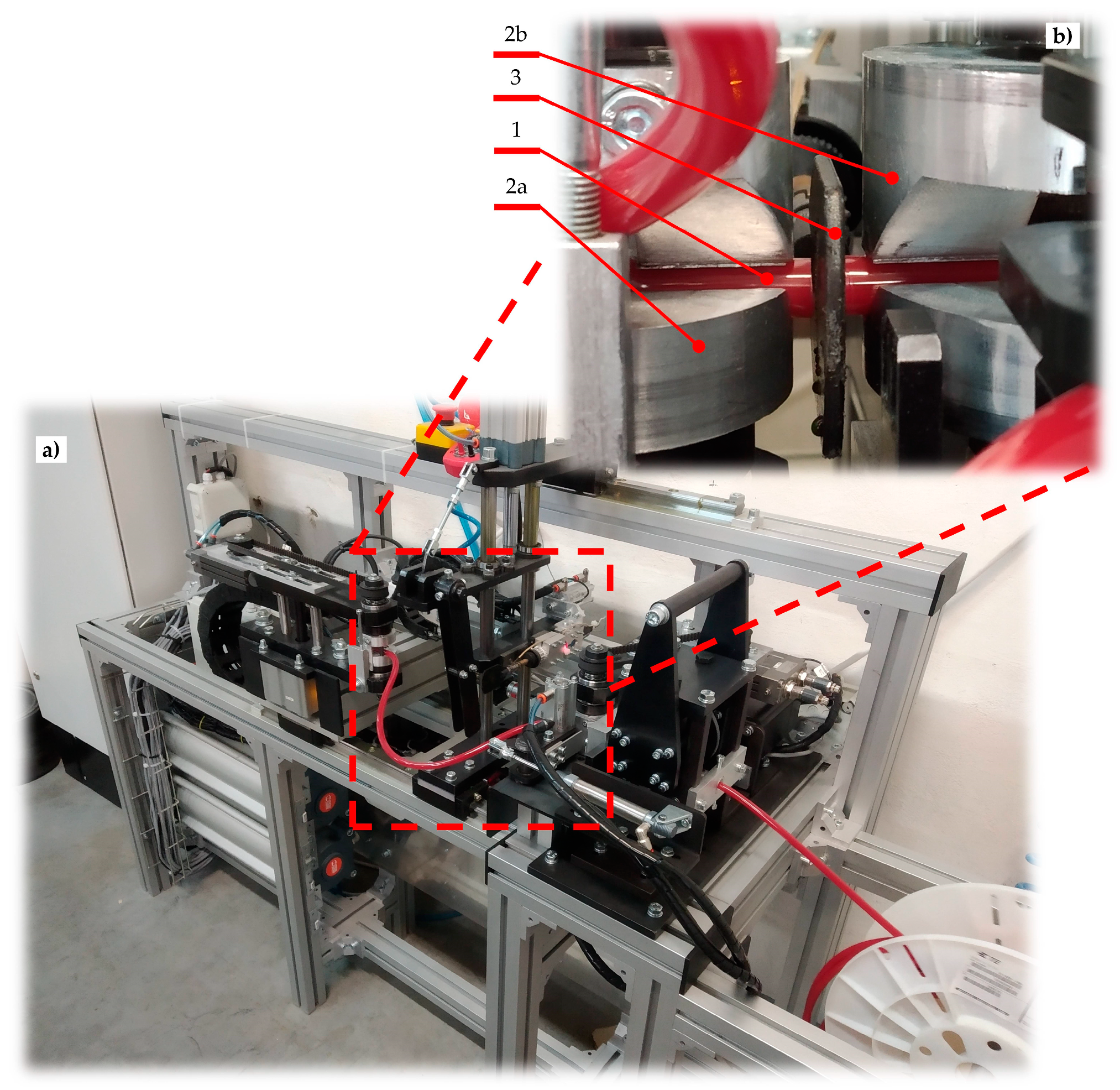
2.2. The Hot Plate Welding Process
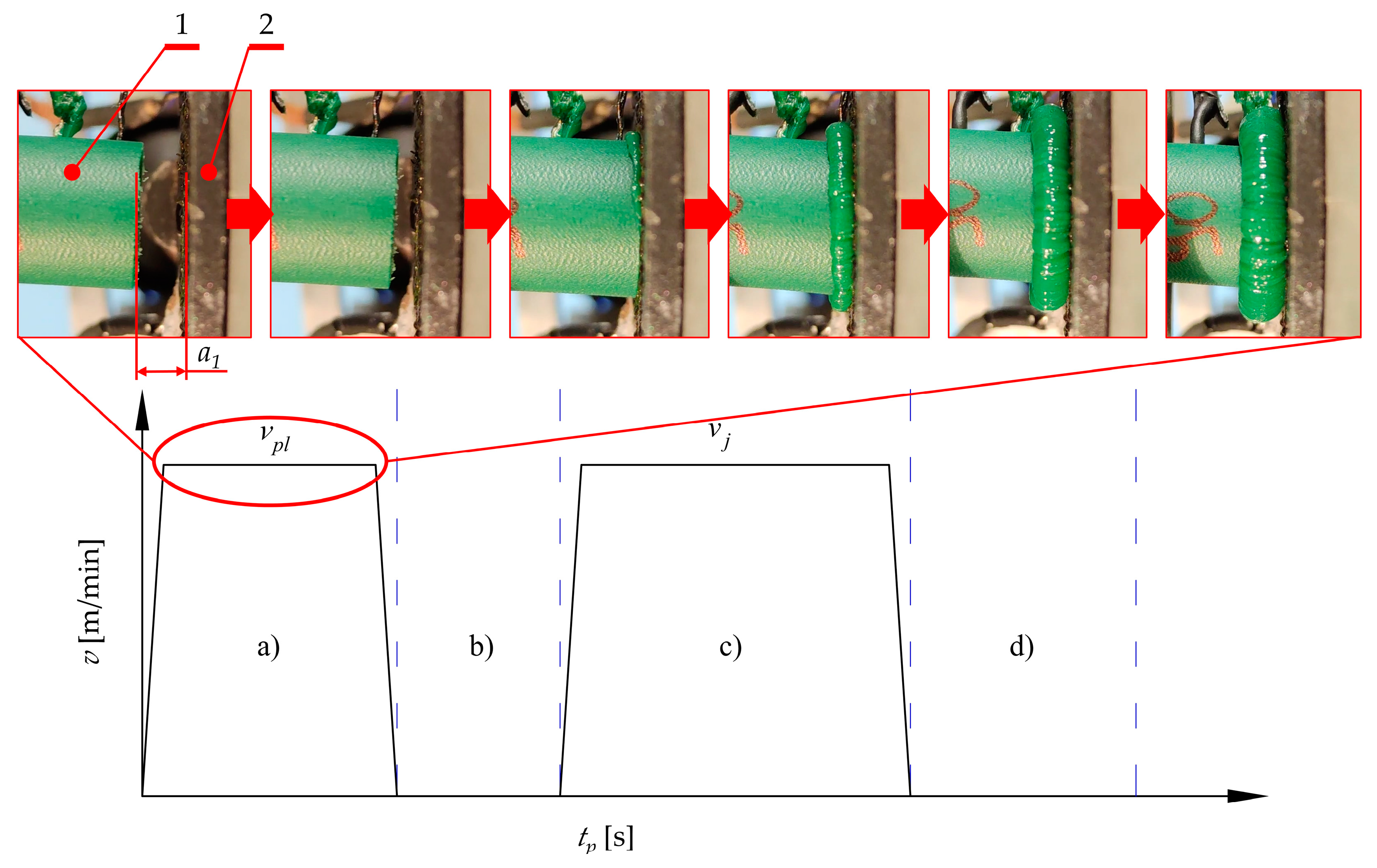
- The plasticization of the belt (Figure 2a), is when the hot plate (3) is pressed to the fixed end of the belt (1b), which is mounted in the fixed belt holder (2b). This is a consequence of a movement of the plate (3) with controlled velocity vpl. Simultaneously, the second end of the belt (1a), which is mounted in the movable belt holder (2a), is pressed to the hot plate (3) from the other side, with controlled velocity 2·vpl. Finally, the relative velocity between the hot plate (3) and fixed end (1b), as well as between the movable end (1a) and hot plate (3), is equal to vpl. The most important feature of this assumption, according to the authors’ intention, consists of simultaneous displacement of the movable end of the belts (1a) and the hot plate (3), which gives the effect of uniform plasticization of both ends of the belt (1a and 1b). Additionally, the plasticization force value Fpl is variable and not regulated because of displacement control, which is easier to implement in industrial conditions. The main objective of this operation is to elevate the temperature of the ends of the belt to a value which is almost equal to the plate temperature Tp, which is higher than the welding temperature Tw (which is given as a material property). This temperature correlation will ensure that the temperature Tw is obtained during the proper joining operation (considering the energy losses due to convection and radiation during the next phases [52]);
- Removing the hot plate (Figure 2b) is when the heating device (3 in Figure 2a) is retracted from the area between the ends of the belt (1a and 1b). At this stage, the heating process in finished. Unfortunately, the ends of the belt (1a and 1b) are cooled by convection with the environment and radiation. For this reason, this stage should be as short as possible to avoid situations when the flat surface of the ends of the belt (1a and 1b) will be cooled down to a temperature which is lower than the welding temperature Tw;
- The pressing phase (Figure 2c) is when the movable end of the belt (1a) is pressed against the fixed one (1b) with velocity vj. This activity is crucial for the overall process. The thermal activation of the belt surface (flat surface of the ends of the belt 1a and 1b) and pressing force at this stage leads to contact between them; therefore, this is where the interactions between the ends (1a and 1b) of the belt begin. They consist of mechanical interactions between polymer macromolecules which lead to their splicing. This phenomenon facilitates the start of the chemical reactions between them [53], which is an action that allows for obtaining a connection. In this phase, only the velocity vj is known and regulated which facilitates the precise control of the operation;
- The cooling phase (Figure 2d) is when the movement of the movable end of the belt (1a) is stopped and compression velocity vc is approximately equal to 0. Despite the fact that there is no pressure to compress the joint, the ends of the belt (1a and 1b) can be pressed together by residual force Fc which might remain after the compression process (Figure 2c). During this phase (Figure 2d), the joint cools down as a result of heat exchange with the environment (convection and radiation). In the ideal situation, the joint should remain in this state for a period of time, allowing its temperature to be lowered to T0. The main assumptions of this phase are connected with equalization of the temperature between the belt ends and the environment and finalization of the chemical reactions and physical interactions between macromolecules.
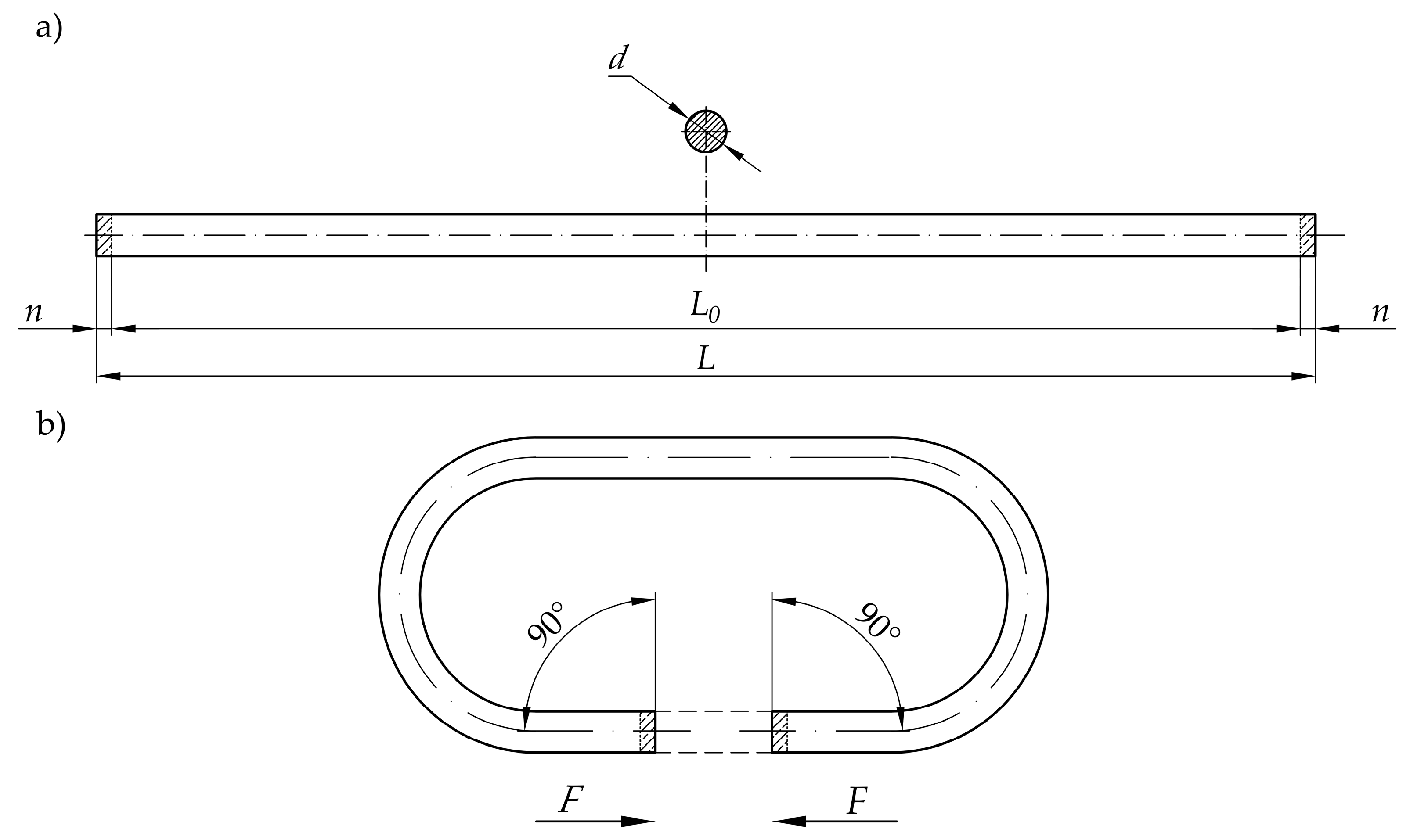
- Precise control of the final length of the belt (L0 in Figure 1), omitting the standard problems during controlling small-value forces, due to displacement regulation;
- Simplifying the control system framework and lowering the complexity of the mechanical design due to using just one drive unit for performing the main technological movements.
2.3. The Conception of Automated Hot Plate Welder
- Dose the belt (P);
- Make a measurement of the length of the dosed belt;
- Cut the belt in a suitable place.
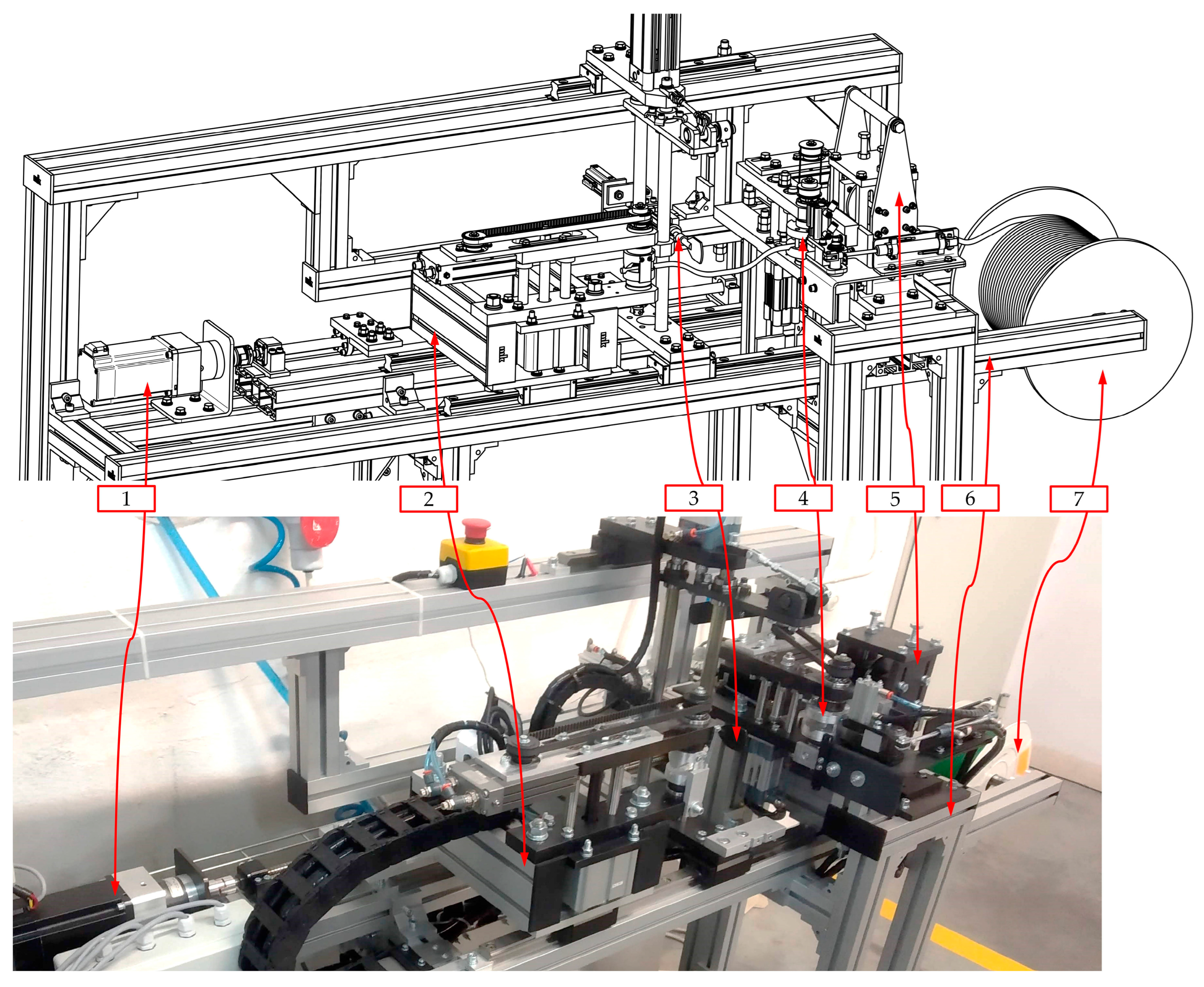
2.4. Industrial Implement of the Automated Welding Machine
- Ensure the proper leading of the belt through all of the mechanical parts;
- Protect against the tangling of the belt by obtaining the initial tension of the strand;
- Make the required manipulation of the ends of the belt in order to achieve proper orientation.
3. Design of the Main Drive
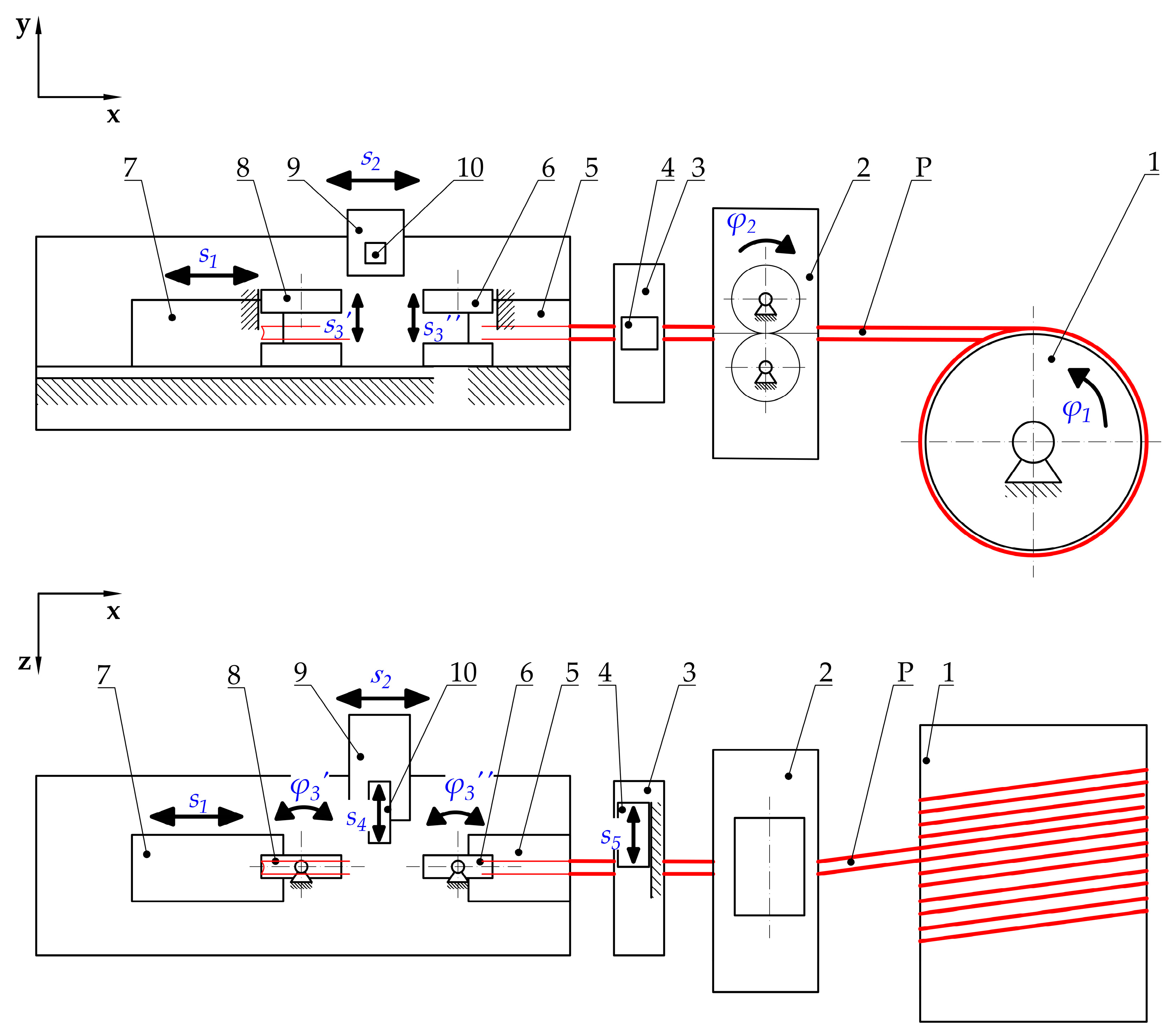
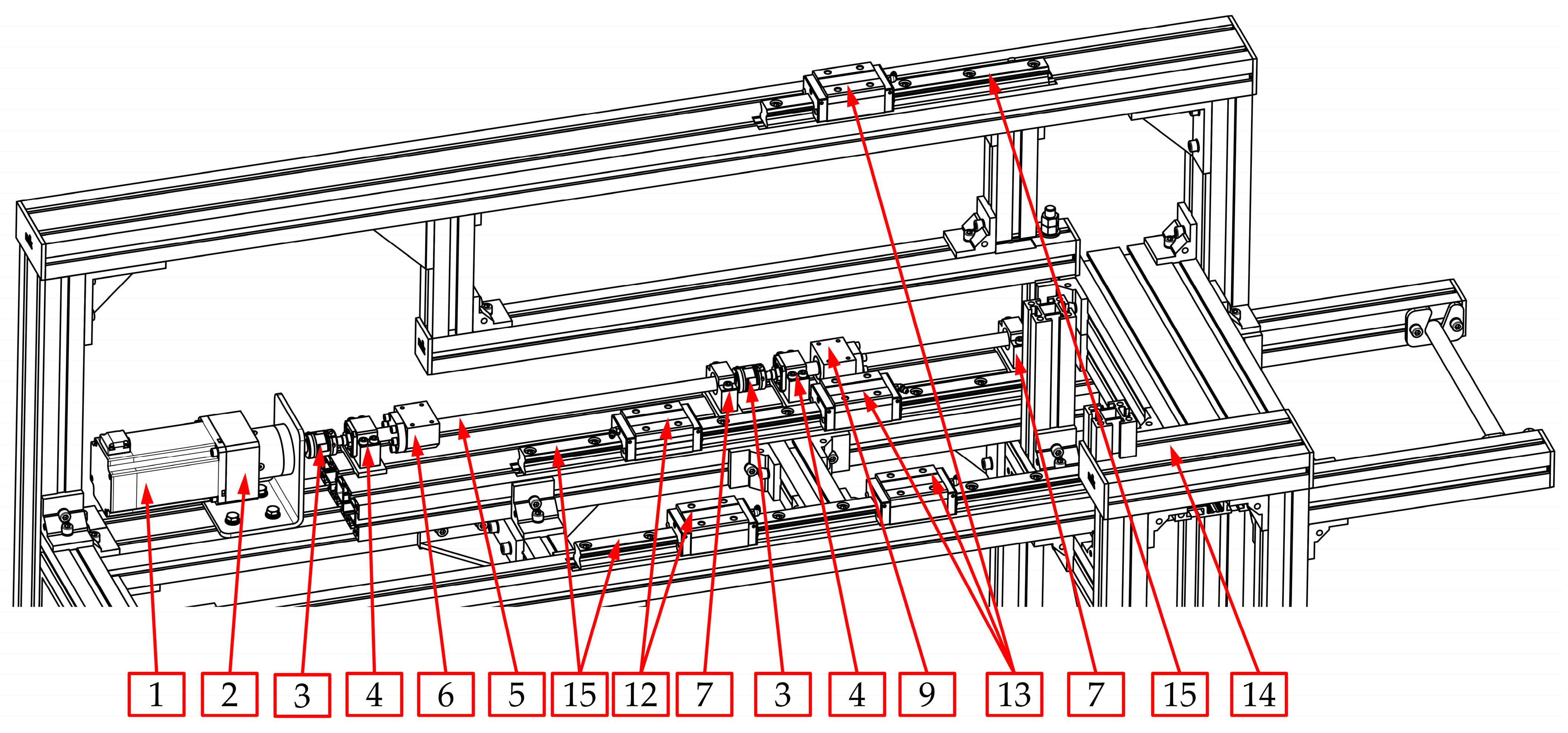
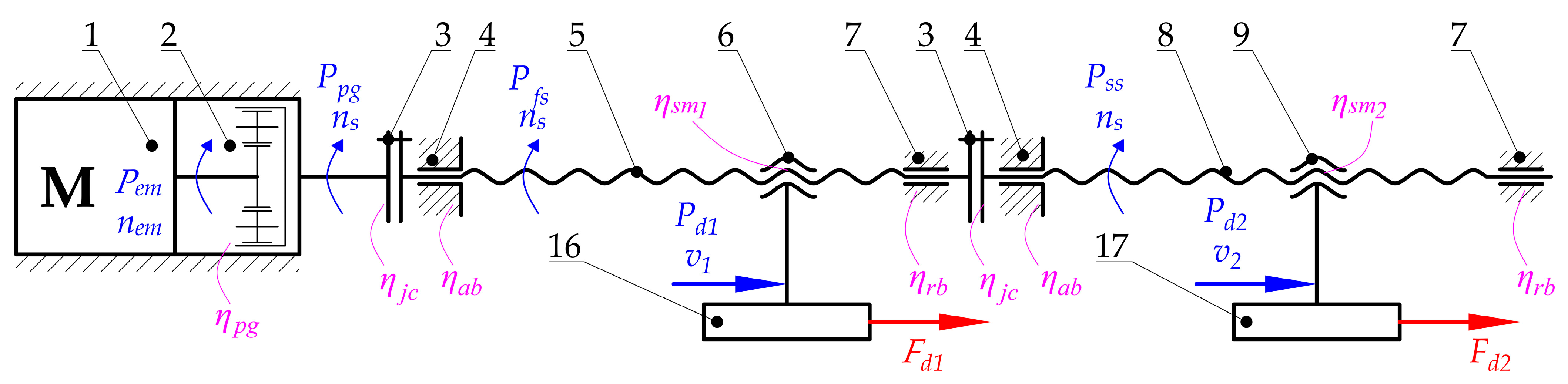
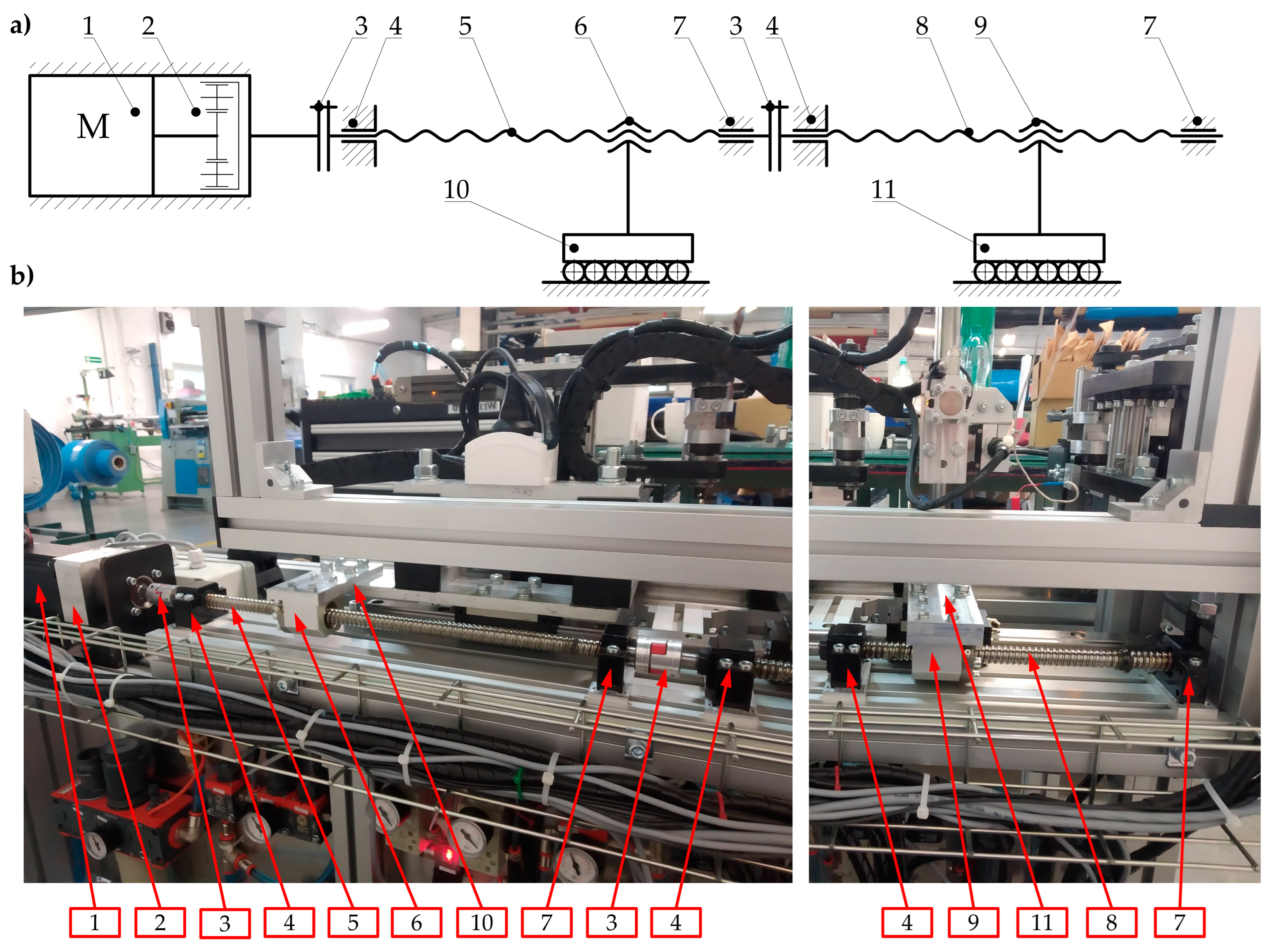
3.1. Structure of the Main Drive
3.2. The Load of the Main Drive
- The values of the efficiency of particular components, especially planetary gear (2), couplings (3), angular and radial bearings (4 and 7), and screw mechanisms (5 and 6, 8 and 9) due to inevitable energy losses resulting from friction;
- Calculations that make it possible to transform the forces that are necessary to drive particular mechanisms (Fd1 and Fd2) for the required power of the motor (Pem);
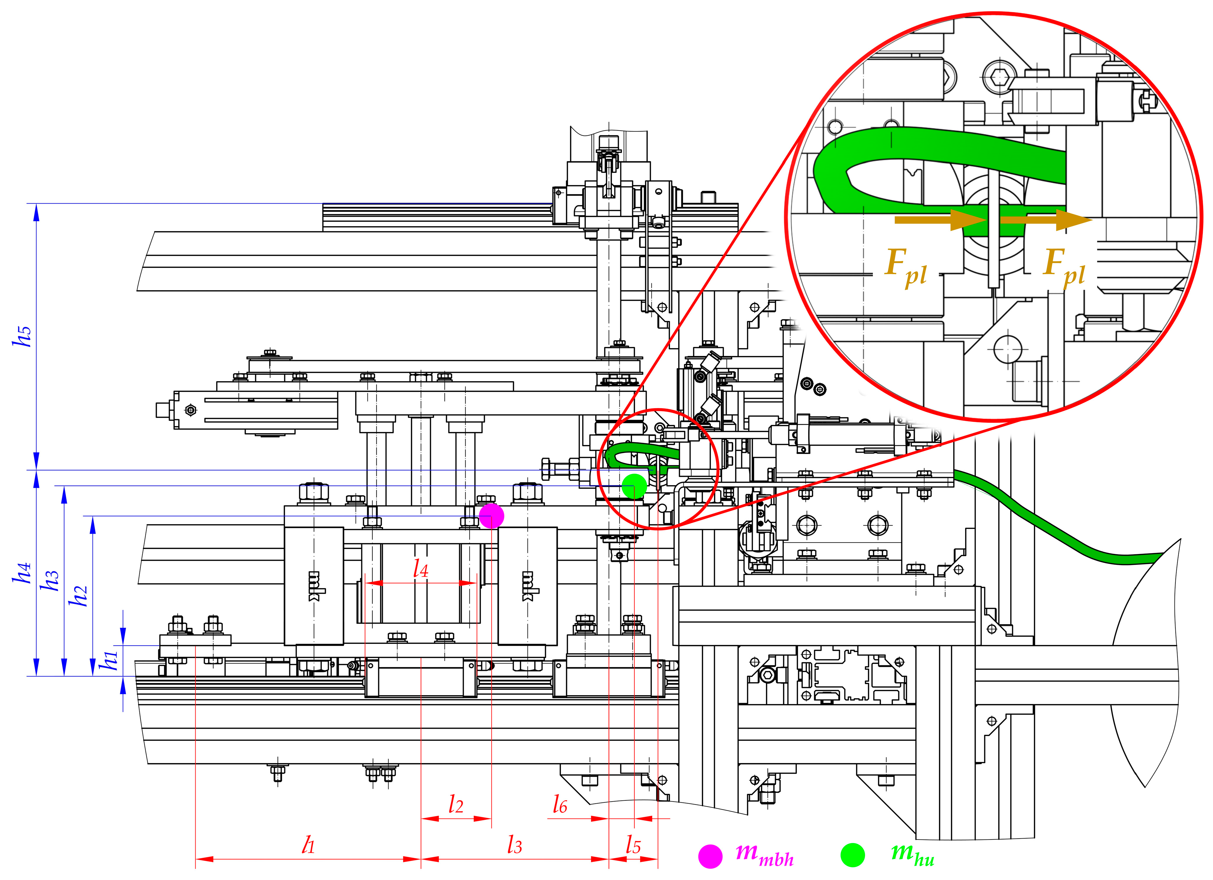
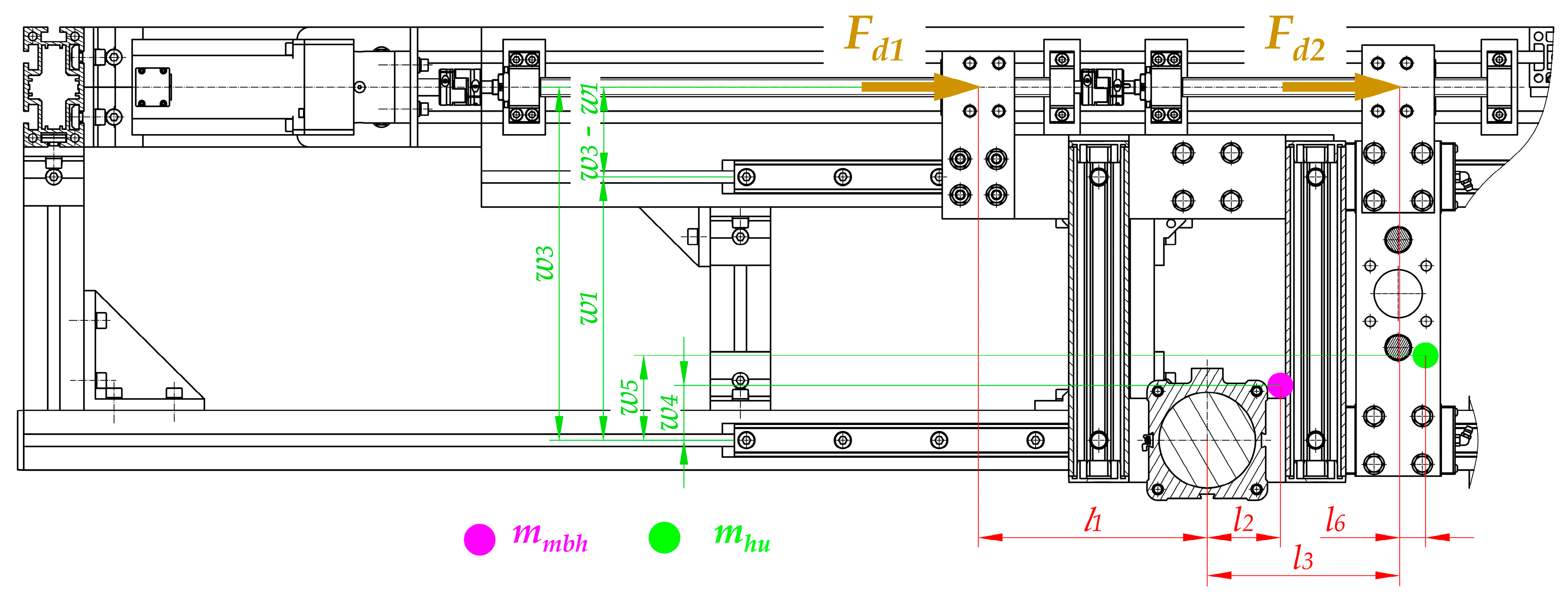
- Calculations that make it possible to transform technological forces (especially the plasticization force Fpl) into forces that are necessary to drive particular mechanisms (Fd1 and Fd2). These types of calculations should be performed regarding particular distances between guiding elements and places where the technological forces act. In addition, the mass of the parts should be considered to obtain all of the force components (Figure 9, Figure 10 and Figure 11).
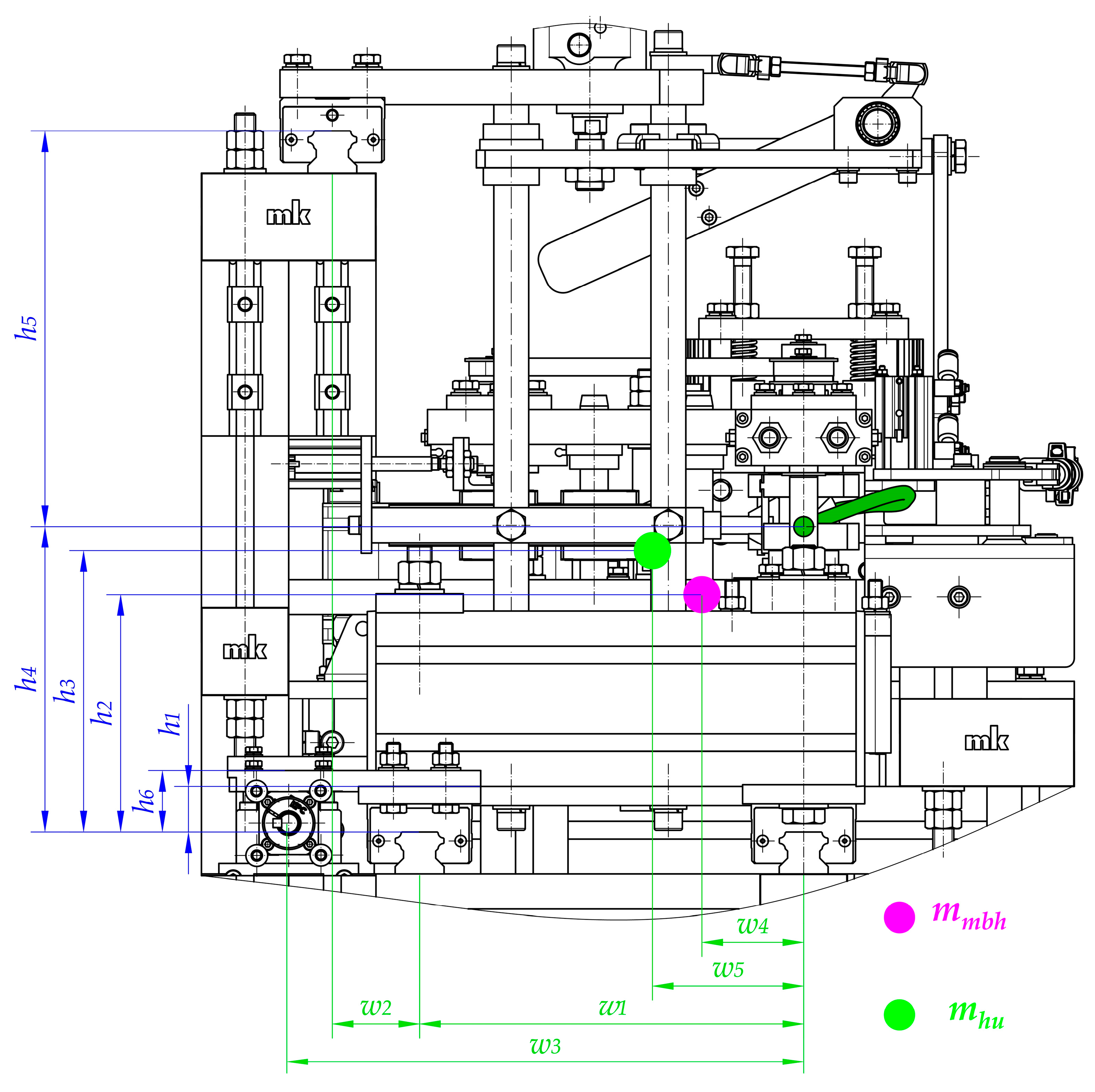
- Distances between the carriages of the linear guideways (h4 + h5, l3, w1, w2);
- Size and length of the carriages (l4)—the same for all of guideways;
- Distances between the places where technological forces act and the carriages of linear guideways (h4, h5, l5, l5 + l3, w1, w1 + w2);
- Distances between the places where the driving force will be applied and the carriages of linear guideways (h1, h6, l1, w3, w3 − w1);
- Values of the masses of the movable belt holder mmbh and the heating unit mhu;
- Distances between the center of the mass of the movable belt holder and the carriages of linear guideways (h2, l2, w4);
- Distances between the center of the mass of the heating unit and the carriages of linear guideways (h3, l6, w5);
- Rolling friction coefficient between carriages and rails μ1.
4. Estimation of the Workload Value during the Plasticization Process
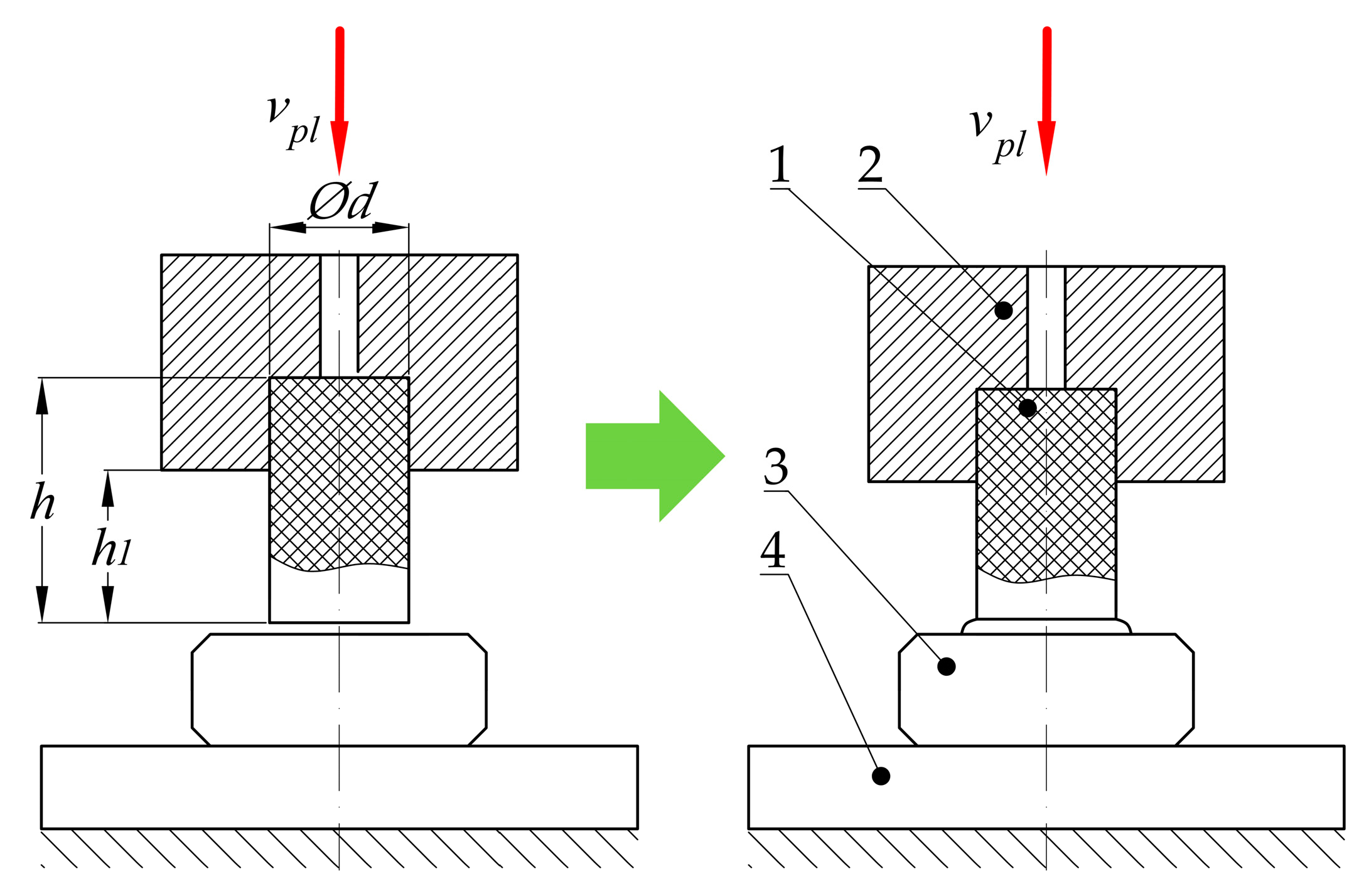
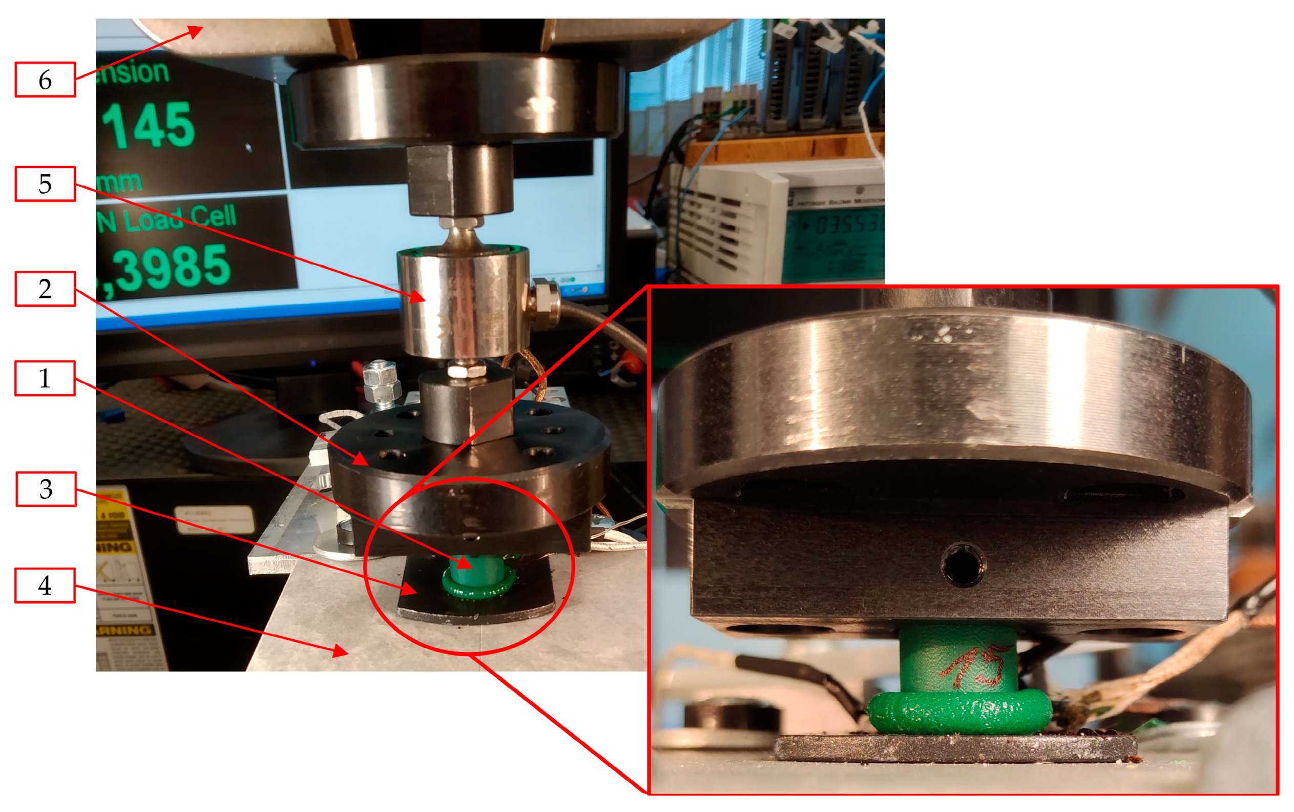
4.1. Tests of the Plasticization Process
- Diameter of the belt d;
- Temperature of the hot plate Tp;
- Plasticization velocity vpl.
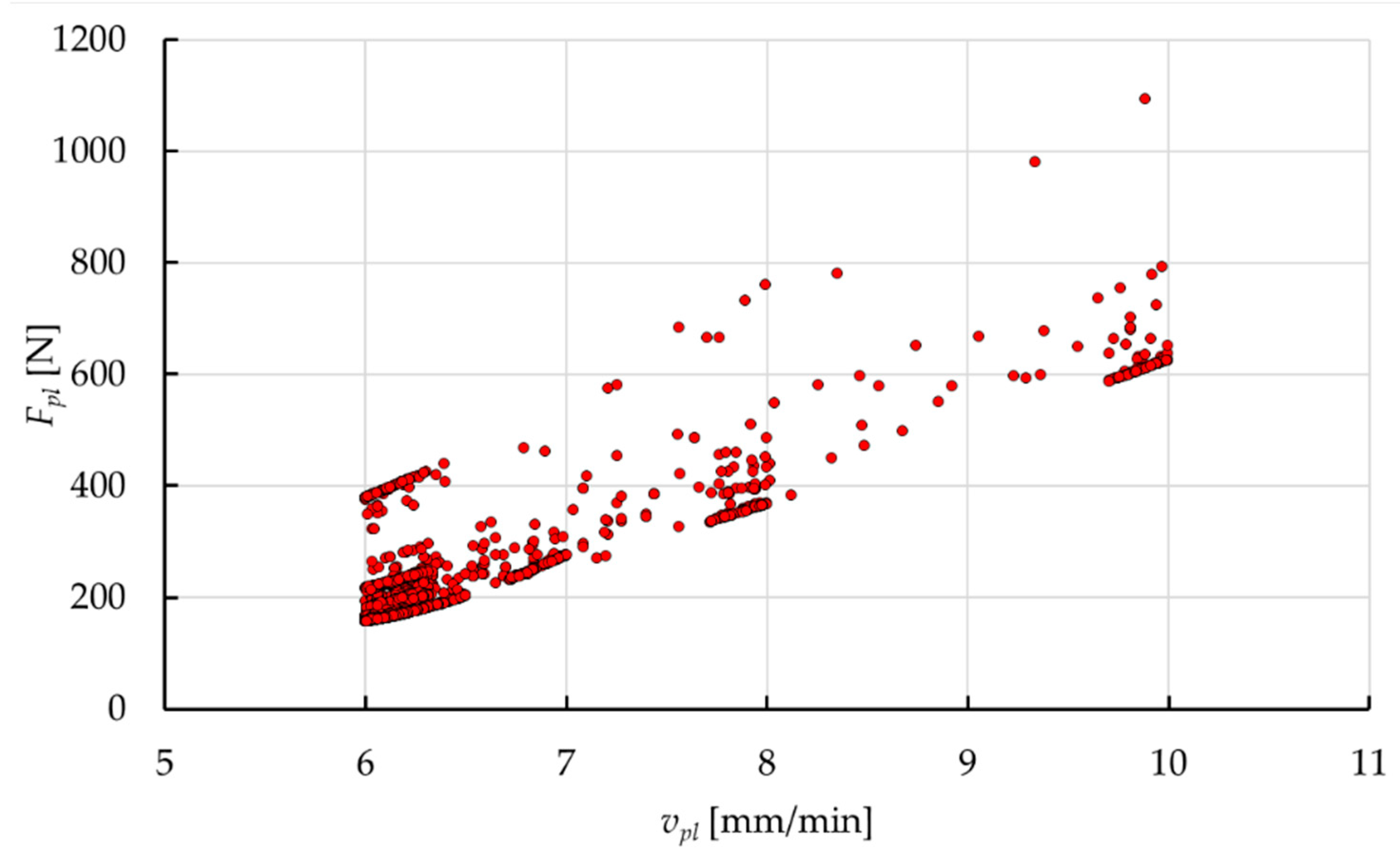
4.2. Results of the Experimental Research
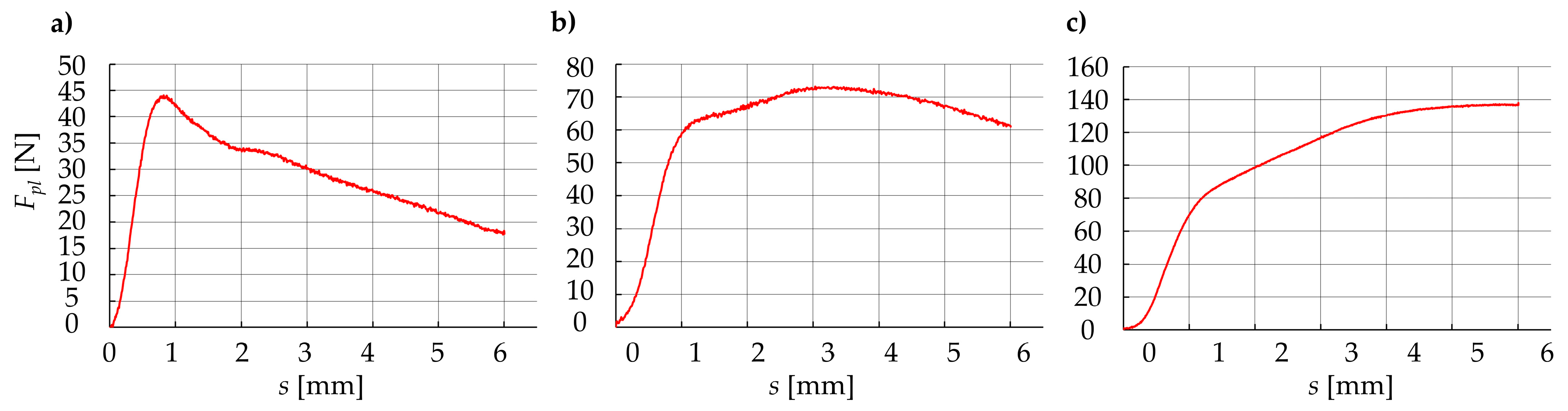
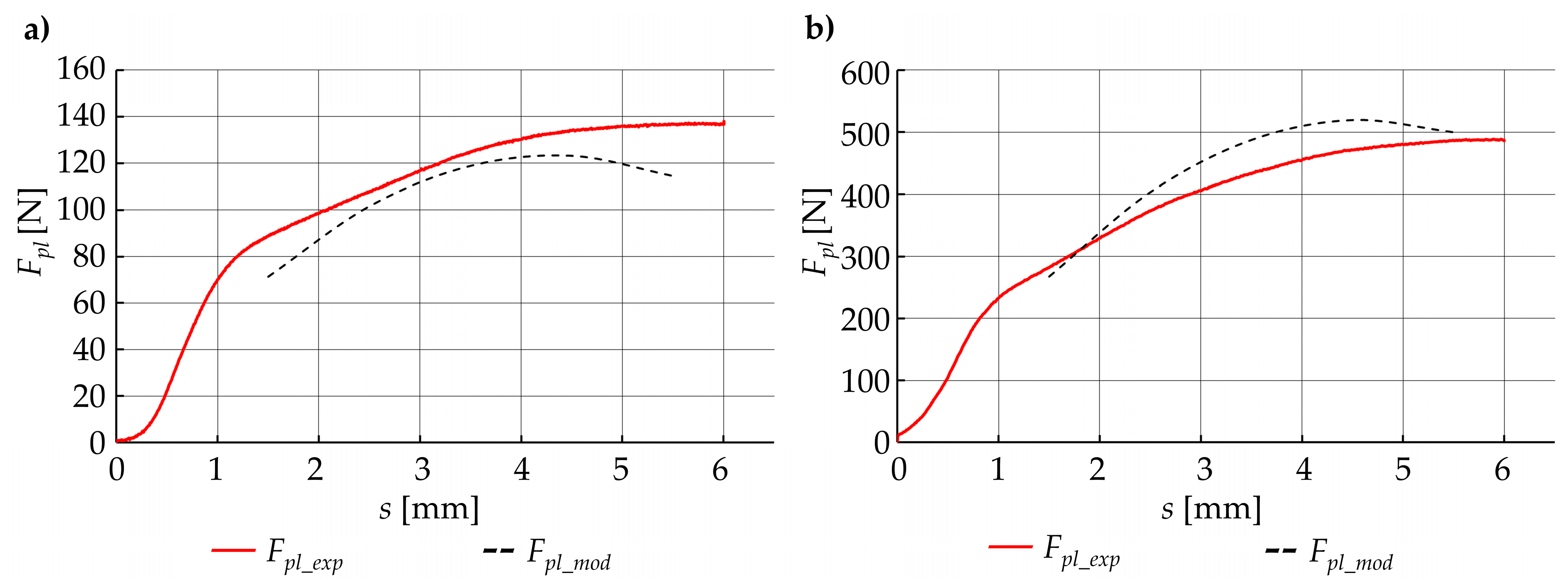
- Value of the plasticization force Fpl first increases almost linearly, then decreases non-linearly (Figure 14a);
- Value of the plasticization force Fpl first increases almost linearly, then it is almost constant with little nonlinear deviation (Figure 14b);
- Value of the plasticization force Fpl first increases almost linearly, then it also increases but in a nonlinear way (Figure 14c).
4.3. Discussion of the Results
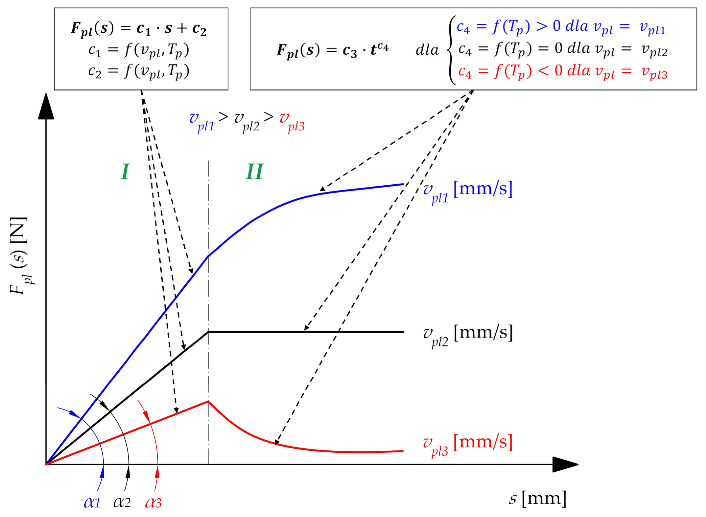
- Phase I, where the plasticization operation can be described as a steady state (almost linear, positive correlation between force Fpl and displacement s);
- Phase II, when the plasticization operation can be described as transient (the correlation between the force Fpl and the displacement s strongly depends on the current technological parameters).
- Assuming a constant diameter of the belt d and a constant temperature of the hot plate Tp, there is a positive correlation between coefficient c1 and plasticization velocity vpl;
- Assuming a constant diameter of belt d and plasticization velocity vpl, there is a negative correlation between coefficient c1 and temperature of the hot plate Tp;
- Assuming a constant plasticization velocity vpl and a constant temperature of the hot plate Tp, there is a positive correlation between proportionality coefficient c1 and diameter of the belt d.
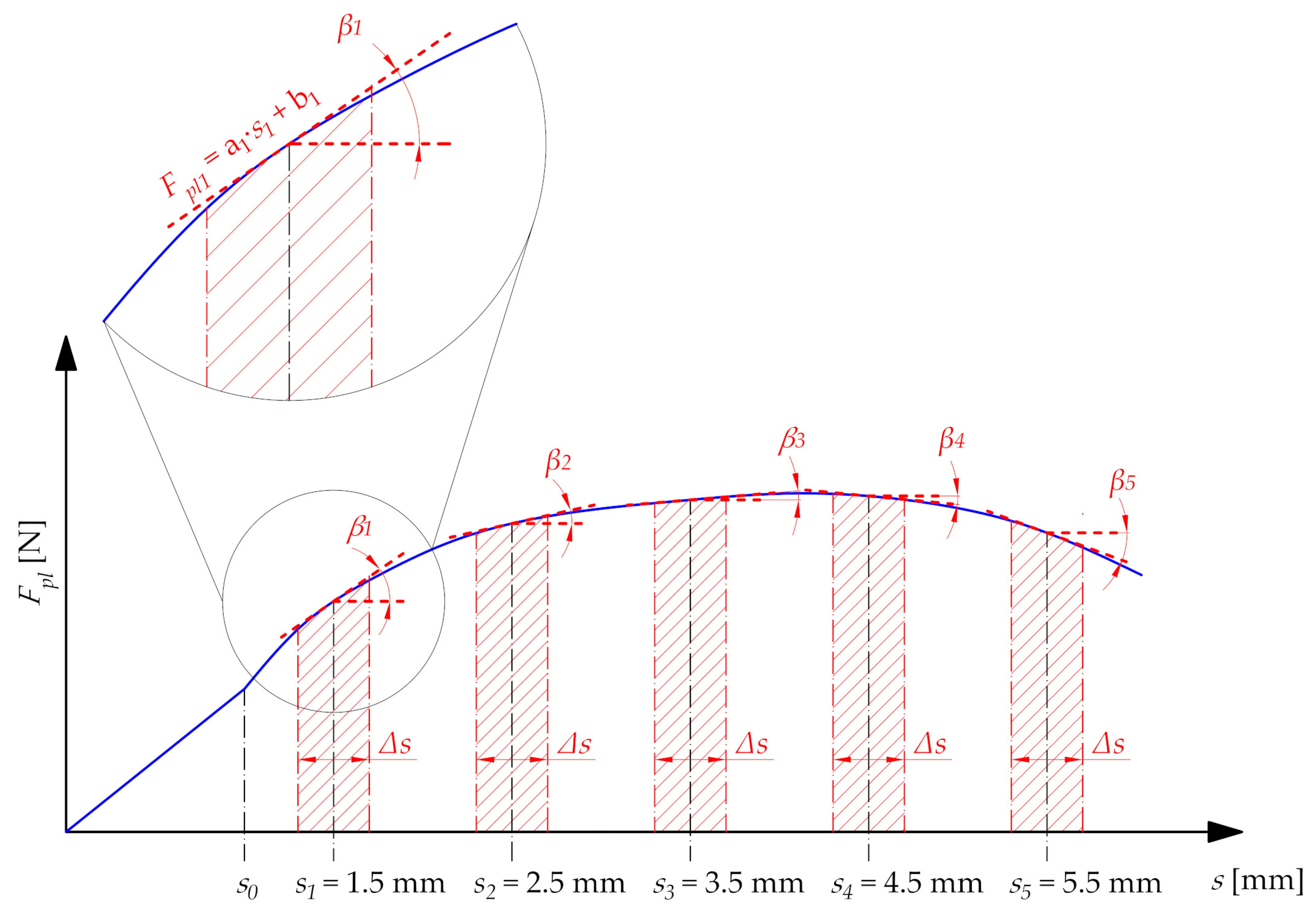
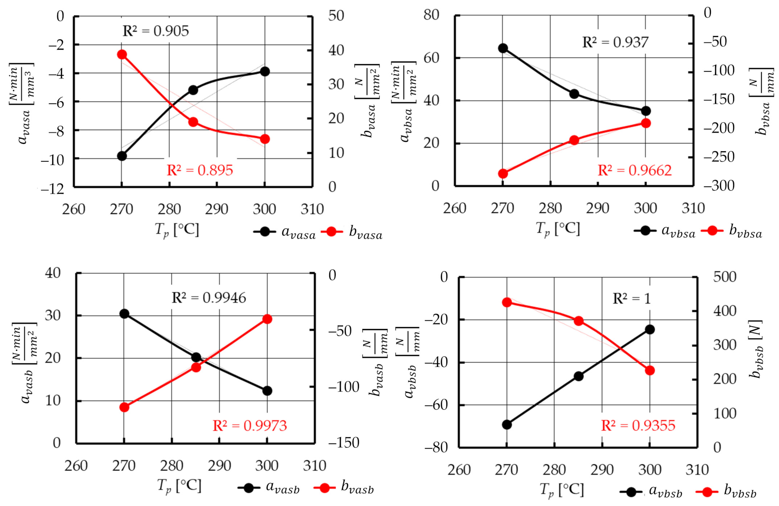
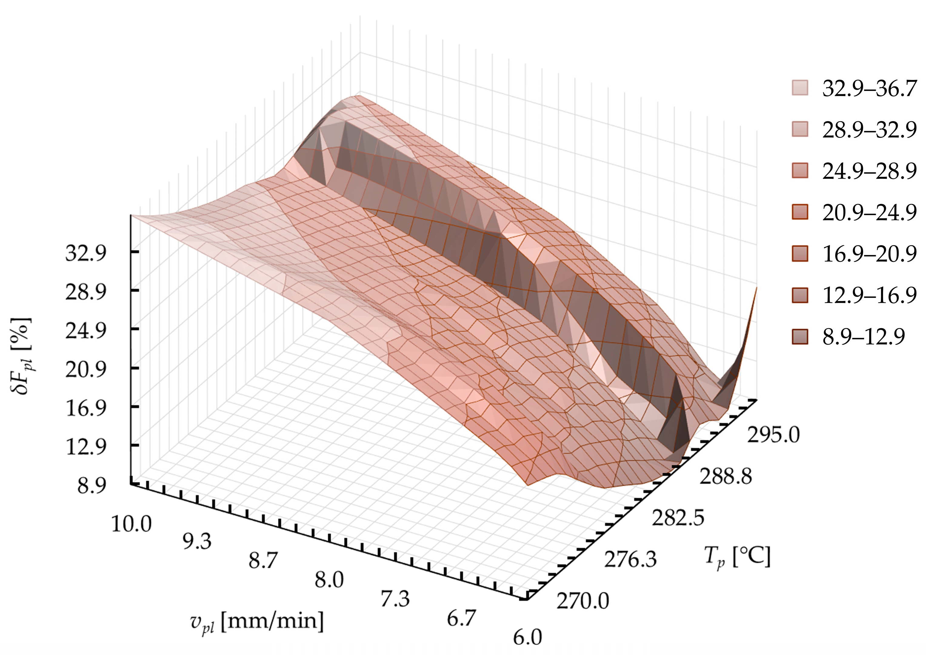
4.4. Plasticization Force Modeling
- Diameter d which varies in a discrete way with values: 12 mm, 15 mm, and 18 mm;
- Temperature of the hot plate Tp which varies continuously from 270 °C to 300 °C;
- Plasticization velocity vpl, which varies continuously from 4 mm/min to 10 mm/min.
4.5. Optimization of the Technological Parameters
- Minimizing the plasticization force Fpl during the entire operation. This target function can be described in a mathematical way as:
- Constant value of the plasticization force Fpl(s) is possible, in the whole calculation range:
- Sequential substitution of the technological parameters of the plasticization operation (vpl, Tp, and s) to call for further iterations of calculations in MS Excel software;
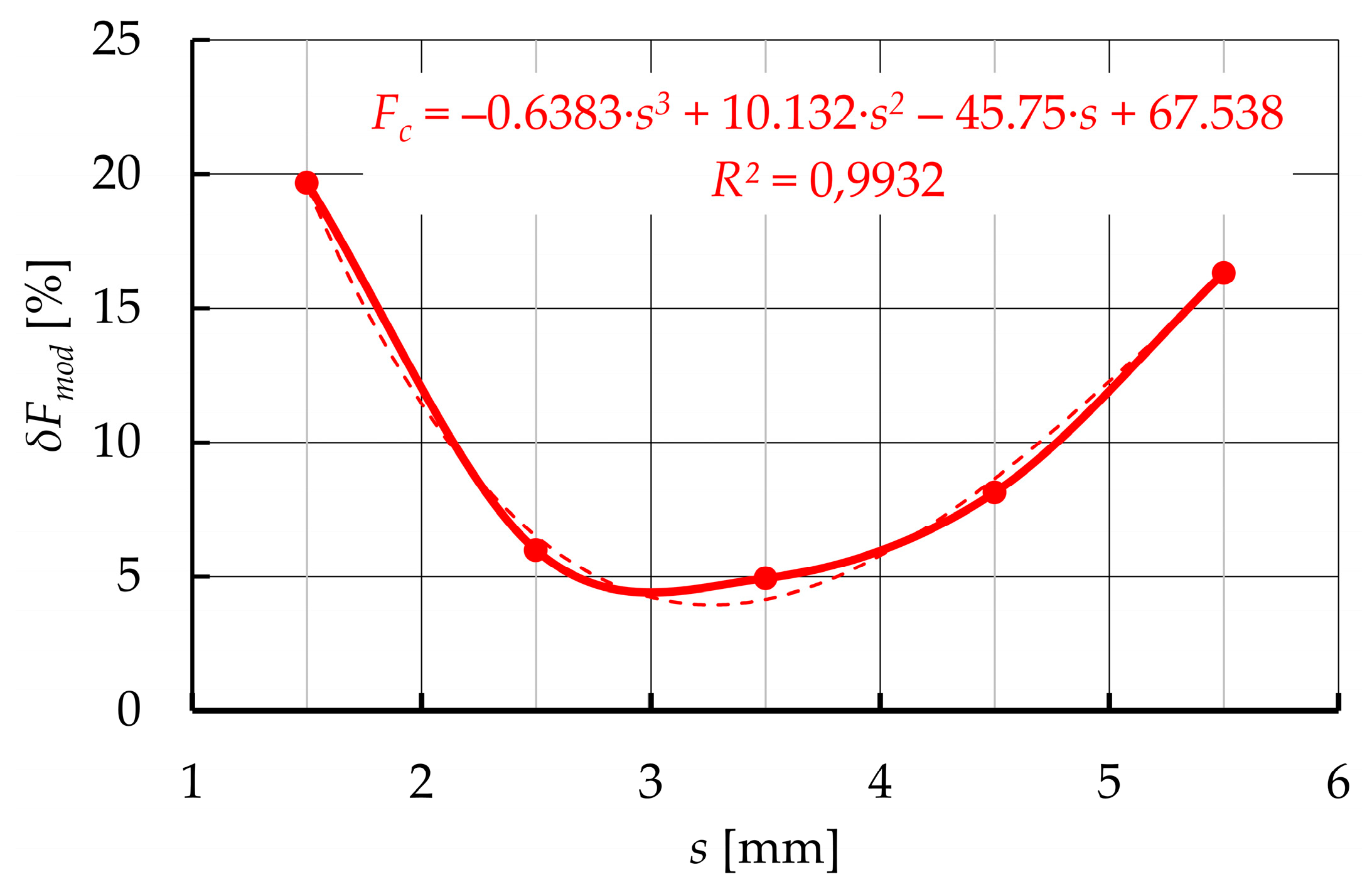
- Collecting the results in the form of values of the current plasticization force Fpl and the current value of the control function δFpl;
- Optimization of the technological parameters (vpl and Tp) to fulfill the target functions (27)–(29).
- Population of 50 individuals;
- 200 generations;
- Double-crossing allowed;
- Scaling factor (due to expected difference in a range of obtained quantities):
5. Estimation of Power Consumption
5.1. Component Selection
- BLDC electric motor (DB series) with built-in planetary gear (GP series) from Nanotec [61];
- Jaw coupling with elastomeric insert (Rotex series) from KTR [62];
- Ball screw mechanisms—a screw with a nut (FSC type with GFD housing) from Hiwin [63]. The initial parameters of the ball screw were set on the basis of initial buckling calculations. The screw to drive the movable belt holder has an effective diameter d1 = 16 mm and a pitch p1 = 10 mm. The screw to drive the heating unit has the same effective diameter d2 = d1 and pitch p2 = 5 mm. Due to that, the assumed correlation Equation (1) between the values of the displacement obtained during rotary movement is obtained;
- Angular bearings with housings (SFA type) from Hiwin [63];
- Radial bearing with housings (SLA type) from Hiwin [63];
- Linear guideways with balls as rolling elements (MSA type) from PMI [64].
- Approximate mass of the movable belt holder is mmbh = 22 kg;
- Approximate mass of heating unit is mhu = 11 kg.
- Planetary gear is ηpg = 0.95;
- Jaw coupling is ηjc = 0.98;
- Angular bearing is ηab = 0.99;
- Radial bearing is ηrb = 0.99;
- Screw mechanism with pitch is p1—friction coefficient ηsm1 = 0.92;
- Screw mechanism with pitch is p2—friction coefficient ηsm2 = 0.85;
- Friction coefficient in linear guideways is μ1 = 0.005.
5.2. Estimation of the Power Consumption
- Mechanisms of technological devices that work with high rotational or linear speed, especially when working speed must be achieved in a short time from the start-up [65];
- Mobile devices capable of overcoming various types of obstacles and moving with relatively high velocity, while achieving relatively high acceleration values [66];
- Positioning and stabilization mechanisms, especially with PID regulation [67].
6. Conclusions
- Conceptual design works;
- Experimental research, which is used for mapping a technological process to determine technological parameters;
- Mathematical modeling of the course of technological operation, in order to determine the load forces;
- Optimization in terms of energy efficiency process, using a genetic algorithm;
- Analysis of the construction of the structure to determine the forces necessary for the driving of individual components;
- The final calculation of power consumption, a structural problem was solved, which consisted of determining the power of the drive components. In addition, as a result of the work carried out, a relatively simple structural solution of the device was obtained, especially concerning the aspect of the drive system. The modularity of the structure allows the device to expand with, among others, the unit for butt removal. The works made are a fragment of a wider spectrum of considerations that have been committed on the occasion of designing this device.
Author Contributions
Funding
Institutional Review Board Statement
Informed Consent Statement
Data Availability Statement
Conflicts of Interest
References
- Wałęsa, K.; Malujda, I.; Talaśka, K.; Wilczyński, D. Process analysis of the hot plate welding of drive belts. Acta Mech. Autom. 2020, 14, 84–90. [Google Scholar] [CrossRef]
- Wojtkowiak, D.; Talaśka, K. Determination of the effective geometrical features of the piercing punch for polymer composite belts. Int. J. Adv. Manuf. Technol. 2019, 104, 315–332. [Google Scholar] [CrossRef] [Green Version]
- Behabelt. Product Catalogue 2019/2020; Behabelt: Glottertal, Germany, 2015. [Google Scholar]
- Krawiec, P.; Domek, G. Transmissions with V-Belts; Wydawnictwo Politechniki Poznańskiej: Poznań, Poland, 2019. [Google Scholar]
- Wałęsa, K.; Malujda, I.; Talaśka, K. Butt welding of round drive belts. Acta Mech. Autom. 2018, 12, 115–126. [Google Scholar] [CrossRef] [Green Version]
- Amanat, N.; James, N.L.; McKenzie, D.R. Welding methods for joining thermoplastic polymers for the hermetic enclosure of medical devices. Med. Eng. Phys. 2010, 32, 690–699. [Google Scholar] [CrossRef]
- Watson, M.N.; Murch, M.G. Recent developments in hot plate welding of thermoplastics. Polym. Eng. Sci. 1989, 29, 1382–1386. [Google Scholar] [CrossRef]
- Gehde, M.; Bevan, L.; Ehrenstein, G.W. Analysis of the deformation of polypropylene hot-tool butt welds. Polym. Eng. Sci. 1992, 32, 586–592. [Google Scholar] [CrossRef]
- Stokes, V.K. A phenomenological study of the hot-tool welding of thermoplastics. Part 1: Polycarbonate. Polymer 1999, 40, 6235–6263. [Google Scholar] [CrossRef]
- Stokes, V.K. Experiments on the hot-tool welding of three dissimilar thermoplastics. Polymer 1998, 39, 2469–2477. [Google Scholar] [CrossRef]
- Stokes, V.K. Toward a Weld-Strength Data Base for Hot-Tool Welding of Thermoplastics; Society of Plastics Engineers Inc.: Newtown, CT, USA, 1995; Volume 1, pp. 1280–1284. [Google Scholar]
- Potente, H. Zur Theorie des Heizelement-Stumpfschweißens. Kunstoffe 1977, 2, 98–102. [Google Scholar]
- Potente, H.; Brüßel, A. Investigations into Increasing Weld Strength through the Use of Profiled Hot Plates; Society of Plastics Engineers Inc.: Newtown, CT, USA, 1997; Volume 1, pp. 1233–1237. [Google Scholar]
- Potente, H.; Tappe, P. Scale-up laws in heated tool butt welding of HDPE and PP. Polym. Eng. Sci. 1989, 29, 1642–1648. [Google Scholar] [CrossRef]
- Potente, H.; Natrop, J. Computer-Aided optimization of the parameters of heated-tool butt welding. Polym. Eng. Sci. 1989, 29, 1649–1654. [Google Scholar] [CrossRef]
- Potente, H.; Schöppner, V.; Hoffschlag, R.; Gövert, S.; Schnieders, J. In-Line Process Optimization of Hot-Tool Welding Using Innovative Actuation Concept; Society of Plastics Engineers Inc.: Newtown, CT, USA, 2009; Volume 1, pp. 745–749. [Google Scholar]
- Nonhof, C.J. Optimization of hot plate welding for series and mass production. Polym. Eng. Sci. 1996, 36, 1184–1195. [Google Scholar] [CrossRef]
- Cocard, M.; Grozav, I.; Iacob, M.; Caneparu, A. Establishing the optimum welding procedure for PE 100 polyethylene pipelines using the Response Surface Design. Mater. Plast. 2009, 46, 452–457. [Google Scholar]
- Poopat, B.; Wu, C.Y.; Benatar, A.; Park, J.B. Optimization of Contact Hot Plate Welding of HDPE; Society of Plastics Engineers Inc.: Newtown, CT, USA, 1999; Volume 1, pp. 1386–1390. [Google Scholar]
- Riahi, M.; Kooshayan, K.; Ghanati, M.F. Analysis of effect of pressure and heat on mechanical characteristics of butt fusion welding of polyethylene pipes. Polym. Plast. Technol. Eng. 2011, 50, 907–915. [Google Scholar] [CrossRef]
- Oliveira, M.J.; Duarte, F.M.; Tchalamov, D.; Cunha, A.M. Hot Plate Welding of Glass Reinforced Polypropylene; Society of Plastics Engineers Inc.: Newtown, CT, USA, 2001; Volume 1, pp. 1251–1255. [Google Scholar]
- Wood, A.S. The butt-fusion welding of polymers. Chem. Eng. Sci. 1993, 48, 3071–3082. [Google Scholar] [CrossRef]
- Yoo, J.H.; Choi, S.; Nam, J.; Ahn, K.H.; Oh, J.S. Numerical analysis of the heat transfer and fluid flow in the butt-fusion welding process. Korea-Aust. Rheol. J. 2017, 29, 37–49. [Google Scholar] [CrossRef]
- Ezekoye, O.A.; Lowman, C.D.; Fahey, M.T.; Hulme-Lowe, A.G. Polymer weld strength predictions using a thermal and polymer chain diffusion analysis. Polym. Eng. Sci. 1998, 38, 976–991. [Google Scholar] [CrossRef]
- Nieh, J.Y.; Ni, J.; Lee, J. Hot plate welding of Polypropylene. Part II: Process simulation. Polym. Eng. Sci. 1998, 38, 1133–1141. [Google Scholar] [CrossRef]
- Lee, B.Y.; Kim, J.S.; Lee, S.Y.; Kim, Y.K. Butt-welding technology for double walled Polyethylene pipe. Mater. Des. 2012, 35, 626–632. [Google Scholar] [CrossRef]
- Wojtkowiak, D.; Talaśka, K.; Malujda, I.; Domek, G. Estimation of the perforation force for polymer composite conveyor belts taking into consideration the shape of the piercing punch. Int. J. Adv. Manuf. Technol. 2018, 98, 2539–2561. [Google Scholar] [CrossRef] [Green Version]
- Wojtkowiak, D.; Talaśka, K. Evaluation of the belt punching process efficiency based on the resistance force of the compressed material. Int. J. Adv. Manuf. Technol. 2020, 110, 717–727. [Google Scholar] [CrossRef]
- Górecki, J.; Talaśka, K.; Wałęsa, K.; Wilczyński, D.; Wojtkowiak, D. Mathematical Model Describing the Influence of Geometrical Parameters of Multichannel Dies on the Limit Force of Dry Ice Extrusion Process. Materials 2020, 13, 3317. [Google Scholar] [CrossRef] [PubMed]
- Bahrami-Samani, M.; Agahi, M.; Moosavian, S.A.A. Design and analysis of a welding robot. In Proceedings of the 2006 IEEE International Conference on Automation Science and Engineering, Shanghai, China, 8–10 October 2006; pp. 454–459. [Google Scholar]
- Li, A.; Zhang, C.; Li, H.; Xu, Z.; Chen, X.; Qin, G.; Ye, S. Design of automatic welding machine based on PLC. In Proceedings of the 2011 Fourth International Conference on Intelligent Computation Technology and Automation, Shenzhen, China, 28–29 March 2011; pp. 627–630. [Google Scholar]
- Vairis, A.; Frost, M. Design and commissioning of a friction welding machine. Mater. Man. Proc. 2006, 21, 766–773. [Google Scholar] [CrossRef]
- Bindal, T.; Saxena, R.K.; Pandey, S. Design and development of spin welding machine for thermoplastics. IOP Conf. Ser. J. Phys. 2019, 1240, 012091. [Google Scholar] [CrossRef]
- Luo, J.; Wang, X.J.; Wang, J.X. New technological methods and designs of stir head in resistance friction stir welding. Sci. Technol. Weld. Join. 2009, 14, 650–654. [Google Scholar] [CrossRef]
- Poopat, B.; Benatar, A. Gas-Assisted Non-Contact Hot Plate Welding of HDPE; Society of Plastics Engineers Inc.: Newtown, CT, USA, 2002; Volume 1, pp. 879–884. [Google Scholar]
- Holland, J.H. Adaptation in Natural and Artificial Systems; Massachusetts Institute of Technology Press: Cambridge, MA, USA, 1992. [Google Scholar]
- Goldberg, D.E. Genetic Algorithms in Search, Optimization, and Machine Learning; Addison-Wesley Publishing Company: Reading, MA, USA, 1989. [Google Scholar]
- Liserre, M.; Aquilla, A.D.; Blaabjerg, F. Genethic algorithm-based design of the active damping for an LCL-filter three-phase active rectifier. IEEE Tran. Power Electron. 2004, 19, 76–86. [Google Scholar] [CrossRef]
- Bagis, A. Determination of the PID controller parameters by modified genetic algorithm for improved performance. J. Inf. Sci. Eng. 2007, 23, 1469–1480. [Google Scholar]
- Tang, W.; Tong, L.; Gu, Y. Improved genetic algorithm for design optimization of truss structures with sizing, shape and topology variables. Int. J. Num. Methods Eng. 2005, 62, 1737–1762. [Google Scholar] [CrossRef]
- Kripakaran, P.; Hall, B.; Gupta, A. A genetic algorithm for design of moment-resisting steel frames. Struct. Multidiscip. Opt. 2011, 44, 559–574. [Google Scholar] [CrossRef] [Green Version]
- Dharmadhikari, S.R.; Mahakalkar, S.G.; Jayant, P.G.; Khutafale, N.D. Design and analysis of composite drive shaft using ANSYS and genetic algorithm. Int. J. Mod. Eng. Res. 2013, 3, 490–496. [Google Scholar]
- Lin, F.J.; Chou, W.D.; Huang, P.K. Adaptive sliding-mode controller based on real-time genetic algorithm for induction motor servo drive. IEE Proc. Electr. Power Appl. 2003, 150, 1–13. [Google Scholar] [CrossRef]
- Ali, A.J.; Farej, Z.K.; Sultan, N.S. Performance evaluation of a hybrid fuzzy logic controller based on genetic algorithm for three phase induction motor drive. Int. J. Power Electr. Drive Syst. 2019, 10, 117–127. [Google Scholar] [CrossRef]
- Khater, F.; Shaltout, A.; Hendawi, E.; El-sebah, M.A. PI controller based on genetic algorithm for PMSM drive system. IEEE Int. Symp. Ind. Electr. 2009, 1, 250–255. [Google Scholar]
- Montazeri-Gh, M.; Poursamad, A.; Ghalichi, B. Application of genetic algorithm for optimization of control strategy in parallel hybrid electric vehicles. J. Frankl. Inst. 2006, 343, 420–435. [Google Scholar] [CrossRef]
- Low, K.S.; Wong, T.S. A multiobjective genetic algorithm for optimizing the performance of hard disk drive motion control system. IEEE Tran. Ind. Electr. 2007, 54, 1716–1725. [Google Scholar] [CrossRef]
- Wang, J.; Chen, L.; Xu, Q. Disturbance estimation-based robust model predictive position tracking control for magnetic levitation system. IEEE Tran. Mech. 2021, 27, 81–92. [Google Scholar] [CrossRef]
- Wang, J.; Zhao, L.; Yu, L. Adaptive terminal sliding mode control for magnetic levitation systems with enhanced disturbance compensation. IEEE Tran. Ind. Electr. 2020, 68, 756–766. [Google Scholar] [CrossRef]
- Klimpel, A. Welding of Termoplastics Materials; Wydawnictwo Politechniki Śląskiej: Gliwice, Poland, 2000. [Google Scholar]
- Potente, H.; Schneiders, J.; Bornemann, M. Theoretical model for the one-dimensional temperature and stress calculation of simple hot plate welded geometries. Macromol. Mater. Eng. 2002, 287, 843–853. [Google Scholar] [CrossRef]
- Wałęsa, K.; Malujda, M.; Górecki, J.; Wilczyński, D. The temperature distribution during heating in hot plate welding process. MATEC Web Conf. 2019, 254, 02033. [Google Scholar] [CrossRef]
- Grewell, D.; Benatar, A. Welding of plastics: Fundamentals and new developments. Int. Polym. Proc. 2007, 22, 43–60. [Google Scholar] [CrossRef] [Green Version]
- BASF. Polyurethanes GmbH Thermoplastic Polyurethane Elastomers TPU: Elastollan®—Processing Recommendations; BASF: Lemförde, Germany, 2011. [Google Scholar]
- BASF. Thermoplastic Polyurethane Elastomers: Elastollan®—Material Properties; BASF: Lugwigshafen, Germany, 2017. [Google Scholar]
- Lin, T.T.; Staicovici, S.; Benatar, A. Non-Contact Hot Plate Welding of Polypropylene; Society of Plastics Engineers INC: Newtown, CT, USA, 1996; Volume 1, pp. 1260–1263. [Google Scholar]
- Savija, I.; Culham, J.R.; Yovanovich, M.M. Effective thermophysical properties of thermal interface materials: Part I—Definitions and models. Adv. Electron. Package 2003, 2, 189–200. [Google Scholar]
- Poslinski, A.J.; Stokes, V.K. Steady melting of rectangular thermoplastic bars induced by hot contacting surfaces. Polym. Eng. Sci. 1992, 32, 1147–1162. [Google Scholar] [CrossRef]
- Carslaw, H.S.; Jeager, J.C. Conduction of Heat in Solids; Clarendon Press: Oxford, MS, USA, 1959. [Google Scholar]
- Dassault Systèmes. Isight 4.0, Getting Started Guide; Dassault Systèmes: Cary, NC, USA, 2009. [Google Scholar]
- Nanotec. Product Catalog; Nanotec: Feldkirchen, Germany, 2018. [Google Scholar]
- KTR. Drive Technology; KTR: Rhiene, Germany, 2021. [Google Scholar]
- Hiwin. Ballscrews. Technical Information; Hiwin: Taichung, Taiwan, 2018. [Google Scholar]
- PMI. Linear Guideway; PMI: Taichung, Taiwan, 2018. [Google Scholar]
- Al-Dwairi, A.; Al-Nawafleh, M.A.; Al-Lubani, S.E.; Al-Ghatian, F.M. Lagrangian modeling and analysis of the dynamics of frictional winding mechanisms. Multibody Syst. Dyn. 2011, 26, 175–190. [Google Scholar] [CrossRef]
- Hendzel, Z.; Rykała, Ł. Modelling of dynamics of a wheeled mobile robot with mecanum wheels with the use of Lagrange equations of the second kind. Int. J. Appl. Mech. Eng. 2017, 22, 81–99. [Google Scholar] [CrossRef] [Green Version]
- Rohani, B.; Yazicioglu, Y.; Mutlu, M.; Ogucu, O.; Akgul, E.; Saranli, A. Lagrangian based mathematical modeling and experimental validation of a planar stabilized platform for mobile systems. J. Comp. Appl. Math. 2014, 259, 955–964. [Google Scholar] [CrossRef] [Green Version]


| Parameter | Designation | Value | ||||||||
|---|---|---|---|---|---|---|---|---|---|---|
| Belt diameter | d [mm] | 12 | 15 | 18 | ||||||
| Hot plate temperature | Tp [°C] | 270 ± 1 | 285 ± 1 | 300 ± 1 | 270 ± 1 | 285 ± 1 | 300 ± 1 | 270 ± 1 | 285 ± 1 | 300 ± 1 |
| Plasticization velocity | vpl [mm/min] | 6, 8, 10 | 6, 8, 10 | 6, 8, 10 | 4, 6, 8 | 6, 8, 10 | 6, 8, 10 | 4, 6, 8 | 6, 8, 10 | 6, 8, 10 |
| Specimen height | h [mm] | 25 ± 0.1 | ||||||||
| Specimen protrusion distance | h1 [mm] | 10 ± 0.1 | ||||||||
| Maximal displacement | sMAX [mm] | 6 ± 0.01 | ||||||||
| Parameter | Designation | Value | ||||||||
|---|---|---|---|---|---|---|---|---|---|---|
| Belt diameter | d [mm] | 12 | 15 | 18 | ||||||
| Hot plate temperature | Tp [°C] | 270 ± 1 | 285 ± 1 | 300 ± 1 | 270 ± 1 | 285 ± 1 | 300 ± 1 | 270 ± 1 | 285 ± 1 | 300 ± 1 |
| Plasticization velocity | vpl [mm/min] | 6 | 8 | 10 | 8 | 10 | 6 | 6 | 10 | 8 |
| Location of measurement point | s [mm] | 2.5 | 3.5 | 4.5 | 2.5 | 1.5 | 3.5 | 2.5 | 4.5 | 1.5 |
| Force from experimental research | Fpli_exp [N] | 56.918 | 72.520 | 88.886 | 253.747 | 201.968 | 86.973 | 312.758 | 741.677 | 246.999 |
| Force from modeling | Fpli_mod [N] | 45.193 | 73.199 | 85.927 | 300.144 | 210.657 | 81.419 | 316.090 | 784.093 | 215.600 |
| Deviation of standard model | δFmod [%] | 20.60 | 0.94 | 3.33 | 18.28 | 4.30 | 6.39 | 1.07 | 5.72 | 12.71 |
| Force from corrected model | Fpli_mod_c | 54.409 | 72.111 | 89.847 | 246.347 | 201.192 | 86.175 | 313.959 | 744.032 | 243.062 |
| Deviation of corrected model | δFmod_c [%] | 4.41 | 0.56 | 1.08 | 2.92 | 0.38 | 0.92 | 0.38 | 0.32 | 1.59 |
| Parameter | Designation | Value | ||
|---|---|---|---|---|
| Belt diameter | d [mm] | 12 | 15 | 18 |
| Effective hot plate temperature | Tp_eff [°C] | 277.5 | 292.5 | 300 |
| Effective plasticization velocity | vpl_eff [mm/min] | 6.45 | 6.49 | 6.29 |
| Effective plasticization force from corrected model | Fpli_eff_mod_c [N] | 56.90 | 107.55 | 179.86 |
| Maximal difference between control points from model | δFpli_eff_mod_c [%] | 8.24 | 6.92 | 8.35 |
| Effective plasticization force from experiment | Fpli_eff _exp [N] | 58.58 | 103.32 | 185.56 |
| Maximal difference between control points from experiment | δFpli_eff_exp [%] | 7.95 | 8.03 | 8.47 |
| Deviation of corrected model | δFeff_mod_c [%] | 2.87 | 3.93 | 3.25 |
| Dimension | Value [mm] | Dimension | Value [mm] | Dimension | Value [mm] |
|---|---|---|---|---|---|
| h1 | 26 | l1 | 155 | w1 | 220 |
| h2 | 115 | l2 | 8 | w2 | 50 |
| h3 | 255 | l3 | 158 | w3 | 295 |
| h4 | 240 | l4 | 72 | w4 | 70 |
| h5 | 160 | l5 | 40 | w5 | 133 |
| h6 | 33 | l6 | 3 | - | - |
| Parameter | Designation | Value | ||
|---|---|---|---|---|
| Belt diameter | d [mm] | 12 | 15 | 18 |
| Effective hot plate temperature | Tp [°C] | 277.5 | 292.5 | 300 |
| Effective plasticization velocity | vpl [mm/min] | 6.45 | 6.49 | 6.29 |
| Plasticization force | Fpl [N] | 56.90 | 107.55 | 179.86 |
| Force to drive movable belt holder | Fd1 [N] | 57.98 | 108.63 | 180.94 |
| Force to drive heating unit | Fd2 [N] | 57.44 | 108.09 | 180.40 |
| Required rotational speed of the screw | ns [rpm] | 1.290 | 1.298 | 1.258 |
| Overall power consumption (required power of the electric motor) | Pem [W] | 0.0231 | 0.0437 | 0.0706 |
Publisher’s Note: MDPI stays neutral with regard to jurisdictional claims in published maps and institutional affiliations. |
© 2022 by the authors. Licensee MDPI, Basel, Switzerland. This article is an open access article distributed under the terms and conditions of the Creative Commons Attribution (CC BY) license (https://creativecommons.org/licenses/by/4.0/).
Share and Cite
Wałęsa, K.; Talaśka, K.; Wilczyński, D. Designing of the Electromechanical Drive for Automated Hot Plate Welder Using Load Optimization with Genetic Algorithm. Materials 2022, 15, 1787. https://doi.org/10.3390/ma15051787
Wałęsa K, Talaśka K, Wilczyński D. Designing of the Electromechanical Drive for Automated Hot Plate Welder Using Load Optimization with Genetic Algorithm. Materials. 2022; 15(5):1787. https://doi.org/10.3390/ma15051787
Chicago/Turabian StyleWałęsa, Krzysztof, Krzysztof Talaśka, and Dominik Wilczyński. 2022. "Designing of the Electromechanical Drive for Automated Hot Plate Welder Using Load Optimization with Genetic Algorithm" Materials 15, no. 5: 1787. https://doi.org/10.3390/ma15051787
APA StyleWałęsa, K., Talaśka, K., & Wilczyński, D. (2022). Designing of the Electromechanical Drive for Automated Hot Plate Welder Using Load Optimization with Genetic Algorithm. Materials, 15(5), 1787. https://doi.org/10.3390/ma15051787