Abstract
Crystalline CaMoO4 and rare-earth-doped CaMoO4:RE3+ (RE = Tb, Eu) phosphors were synthesized at room temperature using a co-precipitation method. The crystal structure of the synthesized powder was a tetragonal structure with a main diffraction peak (112) phase. When CaMoO4 was excited at 295 nm, it showed a central peak of 498 nm and light emission in a wide range of 420 to 700 nm. Rare-earth-ion-doped CaMoO4:Tb3+ was excited at 288 nm and a green light emission was observed at 544 nm, and CaMoO4:Eu3+ was excited at 292 nm and a red light emission was observed at 613 nm. To take advantage of the light-emitting characteristics, a flexible composite was manufactured and a color filter that could be used for UV-LEDs was manufactured. In addition, it was suggested that an ink that could be checked only by UV light could be produced and applied to banknotes so as to prevent counterfeiting.
1. Introduction
Rare-earth ions doped in a phosphor act as a sensitizer to transfer energy to the host lattice, or as an activator that receives energy and emits light. To apply phosphors to light-emitting devices such as display panels and white-light-emitting diodes, it is necessary to develop host lattice and activator ions with a high luminous efficiency and good color purity [1,2]. Many researchers are developing various synthetic methods, such as sol−gel methods [3], solid-state reactions [4], and solvothermal synthesis [5] approaches, as part of an effort to develop a high-purity phosphor doped with rare-earth ions. Among the work on phosphors with good color purity and high luminous efficiency, research intended to facilitate the use of molybdate phosphors doped with rare-earth ions in various applications, such as light-emitting devices, lasers, scintillation materials, optical fibers, catalysts, and displays, is attracting attention [6,7,8]. Specifically, calcium molybdate (CaMoO4) can be used in a wide range of applications due to its stable physicochemical properties and the low absorption critical energy of its scheelite structure [9,10]. Kim et al. produced CaMoO4:Eu3+ with Na+ phosphors with a diameter of 5 nm from a TOA-MoO4 complex with calcium, europium, and sodium-oleate (Ca, Eu, and Na-oleate) mixed in toluene using a solvothermal synthesis method, and suggested that the strongest red emission occurred in Ca0.58MoO4:0.21Eu3+, with 0.21Na+ nanophosphors synthesized at 120 °C [11]. Wang et al. used a molten salt method at 270 °C to successfully synthesize nanoparticles with a uniform crystal grain size of about 70 nm with an approximately spherical shape. CaMoO4, with a peak at 508 nm when irradiated with an excitation wavelength of 356 nm, was synthesized [12]. Lim et al. prepared CaMoO4 particles co-doped with erbium and ytterbium ions using a microwave-assisted metathetic method and observed a green light emission signal at 525 nm under excitation at 980 nm [13]. Pereia et al. prepared a precursor using sol−gel heat-treated at 800 °C, synthesized a SrWO4 phosphor with Eu3+ added thereto, and synthesized a red phosphor with a main peak at 614 nm when excited at 393 nm [14]. Xia et al. synthesized a BaMoO4 phosphor doped with Sm3+ at 850 °C using a solid-state method, and observed and reported the change in emission intensity according to doping the materials by doping with Li, Na, and K [15]. In addition to the application cases of phosphors by doping rare earth materials with these metal-based materials, a case of applying copper-added Co3O4 nanocrystals using hydrothermal synthesis to flexible supercapacitors utilizing the conductivity and particle porosity of the material was reported [16]. The studies reported for synthesizing rare-earth-doped CaMoO4 phosphors lacked examples of applications and disadvantages such as heat treatment at high temperature, small amount of synthesis, and long synthesis time. In this study, methods for reducing energy use and various use cases were presented by simplifying the synthesis method and eliminating the heat treatment process. Using the co-precipitation method, crystalline CaMoO4 was synthesized at room temperature and doped with rare-earth ions to synthesize green and red phosphors. To take advantage of these unique light-emitting properties, a flexible composite was made by mixing it with a polymer (silicone base), after which it was manufactured as a color filter feasible for use in a UV-LED chip. In addition, it was suggested that an ink that reacts only with UV light could be produced and applied to banknotes to discourage counterfeiting.
2. Materials and Method
2.1. Synthesis of CaMoO4 and CaMoO4:RE3+ via Co-Precipitation at Room Temperature
Two beakers were prepared to synthesize crystalline CaMoO4 by co-precipitation at room temperature. Here, 1 mmol of calcium nitrate and 100 mL of distilled water were added to beaker “A” and stirred. The same moles of sodium molybdate and distilled water were added to beaker “B”, which was stirred until they were completely dissolved. After 1 h, the two solutions were confirmed to be completely dissolved, and the solution was slowly poured from beaker “B” into beaker “A” and stirred for 3 h. Centrifugation was then conducted to recover the reacted white powder, and the powder was recovered after washing twice to remove the unreacted substances and sodium. The recovered powder was placed in an oven at 80 °C and dried for about 12 h. To use crystalline CaMoO4 as a phosphor material, 0.25 mmol of rare-earth ions (terbium (III) nitrate; Tb3+, europium (III) nitrate; Eu3+) were added to beaker A during the co-precipitation step, and were synthesized using an identical process (Figure 1).
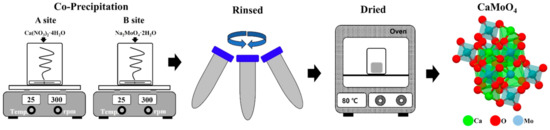
Figure 1.
Schematic of the SrMoO4 synthesis procedure via co-precipitation at room temperature.
2.2. Fabricated of a Flexible Composite
First, 1 wt% of the synthesized CaMoO4 and CaMoO4:RE3+ phosphors were mixed with 5 g of polydimethylsiloxane (PDMS), and were poured into a square mold, put in a vacuum oven at 80 °C, and cured for 2 h to prepare a flexible composite. The prepared composite was photographed for comparison with typical daylight and a UV-lamp, and the color change was observed and photographed by placing it on a UV-LED chip. An anti-counterfeiting ink was prepared by mixing 0.5 wt% of phosphor powder synthesized by doping with rare-earth ions, glycerin (2 g), and ethyl alcohol (4 g). The prepared ink was applied to a bank note with a brush and was examined with the naked eye and under a UV lamp.
2.3. Characterization
To confirm the crystal structure of CaMoO4 synthesized by the co-precipitation method, it was measured at a diffraction angle (2 θ) of 10 to 70° using an X-ray diffraction (XRD; Rigaku Ultima IV, Akishma-shi, Tokyo, Japan) apparatus at a rate of 2° per minute. The size and surface shape of the particles were analyzed through a field-emission transmission microscope (FE-SEM; SU-8220, Hitachi, Chiyoda-ku Tokyo, Japan). The optical properties were investigated at a photomultiplier voltage of 350 V using a fluorescence photometer (Scinco, FS-2, Seoul, Korea) at room temperature. The chemical bonding state was investigated by X-ray photoelectron spectroscopy (XPS; ESCALAB 250 XI, Waltham, MA, USA) and the actual emission wavelength of the manufactured composite was observed using an LED photometer (Gigahertz Optik, S-BTS256, Tuerkenfeld, Germany).
3. Results and Discussion
3.1. Structure and Surface Morphology of Crystalline CaMoO4
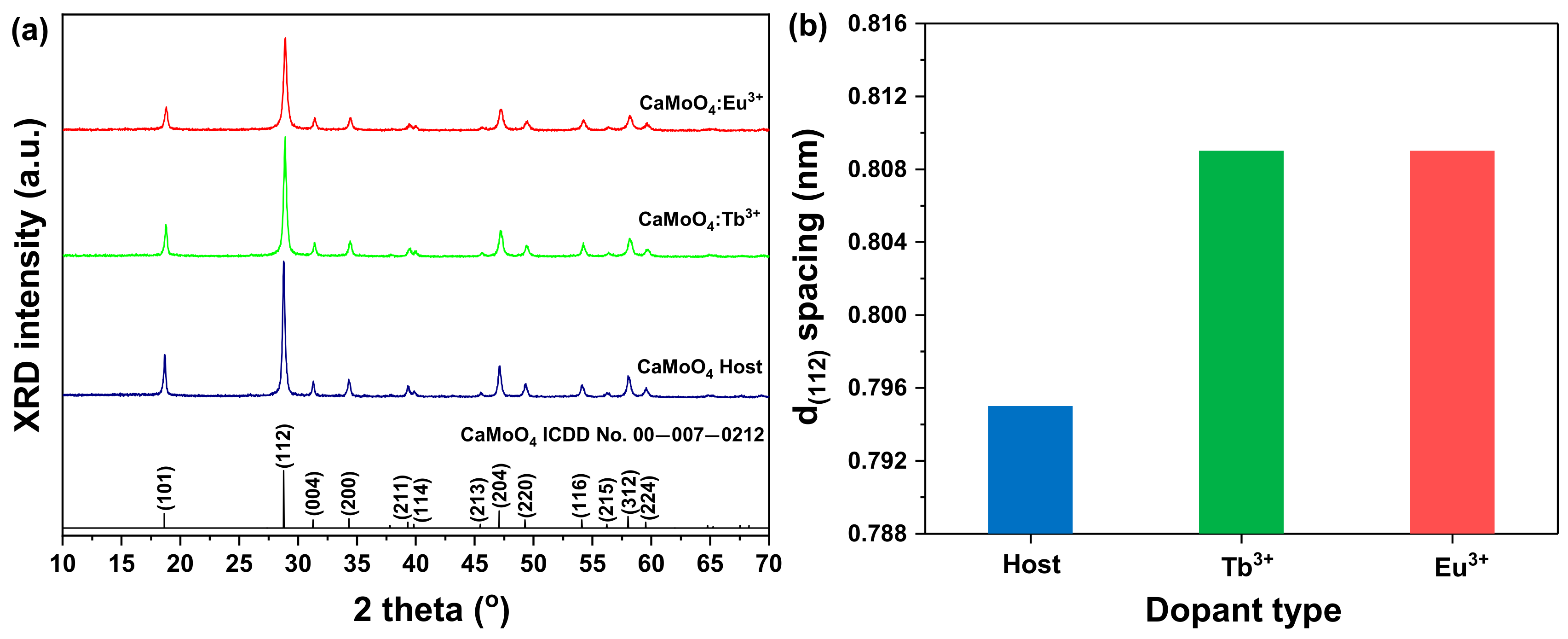
Figure 2a shows the XRD patterns of the CaMoO4 and CaMoO4:RE3+ (RE = Tb3+, Eu3+) samples synthesized at room temperature via co-precipitation. MXO4 (M = Ca, X = Mo) particles were precipitated―M2+cation acted as an electron-to-acceptor (Lewis acid) and reacted with the XO42− anion as an electron-to-donor (Lewis base). The reaction between these two species (M2+ ←: XO42−) continued to produce bonds. The minimum molecular orbital energy of the Lewis acid interacted with the highest molecular orbital energy of the Lewis base, resulting in the synthesis of MXO4 particles [17,18]. For the three samples, peak signals for the (101), (112), (204), (220), and (312) phases were observed, consistent with ICDD card #00-007-0212 and tetragonal (a = 5.2260 Å, b = 5.2260 Å, c = 11.430 Å).

Figure 2.
(a) XRD patterns and (b) d(112) spacing of CaMoO4 and CaMoO4:RE3+.
When the doped rare-earth ions were calculated using a single unit cell of CaoMO4, the calculation showed that the doped amount was about 1.557 × 10¹⁹ RE atoms/cm3 (RE = Tb3+, Eu3+; the calculation process is explained in detail in the Supporting Information). When the diffraction angle of the (112) phase, which is the main diffraction peak, was substituted into Bragg’s equation [19] and compared, as shown in Figure 2b, the lattice constant of the sample to which the rare-earth ions were added was increased (CaMoO4 = 0.795, CaMoO4:Tb3+ = 0.809, CaMoO4:Eu3+ = 0.809). This is thought to be due to the lattice change caused by the doping of rare-earth ions with relatively large ionic radii into the lattice [16]. In addition, the particle size “D” was calculated by substituting the main diffraction angle and full width at half maximum (FWHM) into Scherrer’s equation, as indicated in Equation (1) [19].
Here, n is Scherrer’s constant 0.9, λ is the X-ray wavelength (0.15406 nm), θ is the diffraction angle, and B is the FWHM [16]. Accordingly, CaMoO4 was 30 nm, and for the Tb3+ and Eu3+ single-doped samples, the particle sizes were 29 nm and 25 nm, respectively. The FE-SEM images of the crystal grain sizes and surface shapes of the synthesized CaMoO4 and CaMoO4:RE3+ (RE = Tb3+, Eu3+) samples are shown in Figure 3. The CaMoO4 sample had a cylindrical particle model approximately 3.5 um in size in the longitudinal direction and close to 1.9 um in size in the transverse direction, as particles of about 50 nm in size were aggregated (Figure 3a). In the CaMoO4:RE3+ sample, particles approximately 47 nm in size were agglomerated and had a grain shape with a length of about 1 μm and width of about 0.5 μm (Figure 3b,c). In the FE-SEM EDS mapping component analysis, components such as Ca, Mo, and O were confirmed, and in the rare-earth-doped specimen, the components of Tb and Eu were also confirmed, as shown in Figure S1. In this work, it was shown that the crystalline CaMoO4 and CaMoO4:RE3+ samples synthesized by the co-precipitation method could be synthesized at room temperature without an additional heat treatment process.
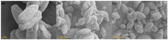
Figure 3.
FE-SEM images of (a) CaMoO4, (b) CaMoO4:Tb3+, and (c) CaMoO4:Eu3+.
3.2. Chemical States and Luminescence Properties of the CaMoO4 Phosphor
An XPS analysis was conducted to determine the chemical state of the synthesized CaMoO4 and CaMoO4:RE3+ samples (Figure 4). The XPS peak corresponded to Ca (2p) with binding energy (BE) outcomes of 346.48 eV (2p3/2) and 350.08 eV (2p1/2). Upon doping with Tb3+ (346.98 eV and 351.68 eV) and Eu3+ (346.78 eV and 352.78 eV) ions, the binding energy value shifted slightly higher (Figure 4b). From the above results, it is assumed that calcium was stable in the +2 oxidation state in both samples. Figure 4c shows the XPS spectra of Mo in the Mo 3d region of undoped CaMoO4 and rare-earth doped CaMoO4 [20]. The peaks around 232 and 235 eV were characteristic of MoO3, probably due to Mo6+ 3d5/2, and 3d3/2, respectively [21]. Mo (3d) showed core BE outcomes of 232.08 eV (3d5/2) and 235.48 eV (3d3/2). Upon doping with rare-earth ions, the binding energy value shifted slightly to the lower energy side (232.05 and 235.38 eV; CaMoO4:Tb3+, 232.04 and 235.38 eV; CaMoO4:Eu3+). Based on these results and the BE values, it was concluded that molybdenum was stable in the +6 oxidation state in both undoped and rare-earth-doped CaMoO4. Figure 4d presents the O 1s core-level peaks of the CaMoO4 and CaMoO4:RE3+ samples. In this case, the O 1s core-level peak was slightly asymmetric at ~530 eV and fitted two symmetric Gaussian curves, denoted by Oa (blue line) and Ob (red line) peaks. The Oa peak was attributed to the lattice oxygen atoms of CaMoO4. There were quite a few reports indicating that the high-energy peak (Ob) of O 1s was due to hydroxyl or chemisorbed oxygen and organic oxygen on the sample surface, such as CO or COO− [22]. However, the asymmetric feature of the high-energy peak (Ob) of the O 1s XPS spectrum demonstrated the presence of oxygen vacancies in the sample. Gupta et al. observed that the Ob peak developed with an increase in the number of oxygen vacancies [23]. Comparing the integrated area ratio of Ob/Oa in CaMoO4 and CaMoO4:RE3+, it can be seen that the area ratio of the CaMoO4:RE3+ was higher than that of CaMoO4, as well as the oxygen vacancy concentration. This was consistent with the fact that after doping divalent Ca2+ sites with trivalent europium ions, the concentration of defects and oxygen vacancies increased [23]. The XPS spectrum outcomes of the rare-earth 3d levels of the CaMoO4:Tb3+ and CaMoO4:Eu3+ samples are correspondingly shown in Figure 4e,f. Two peaks in the Tb3+ 3d region are clearly shown in the spectrum of two peaks. The peak 1241 eV in both samples corresponds to Tb3+ 3d5/2, the peak at 1276 eV (Figure 4e). There are four peaks in the Eu3+ 3d region. The peaks 1124 and 1134 eV in the corresponding samples correspond to Eu3+ 3d5/2, whereas the peaks at 1154 and 1164 eV monitored (Figure 4f). The BE values for Tb3+ and Eu3+ 3d5/2 were consistent with those reported for rare-earth coordinated ions, indicating that the oxidation state of rare-earth ions was +3 in both cases [24,25].
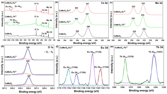
Figure 4.
(a) XPS survey, (b) Ca 2P, (c) Mo 3d, (d) O 1s, (e) Tb 3d, and (f) Eu 3d spectra of CaMoO4 and CaMoO4:RE3+.
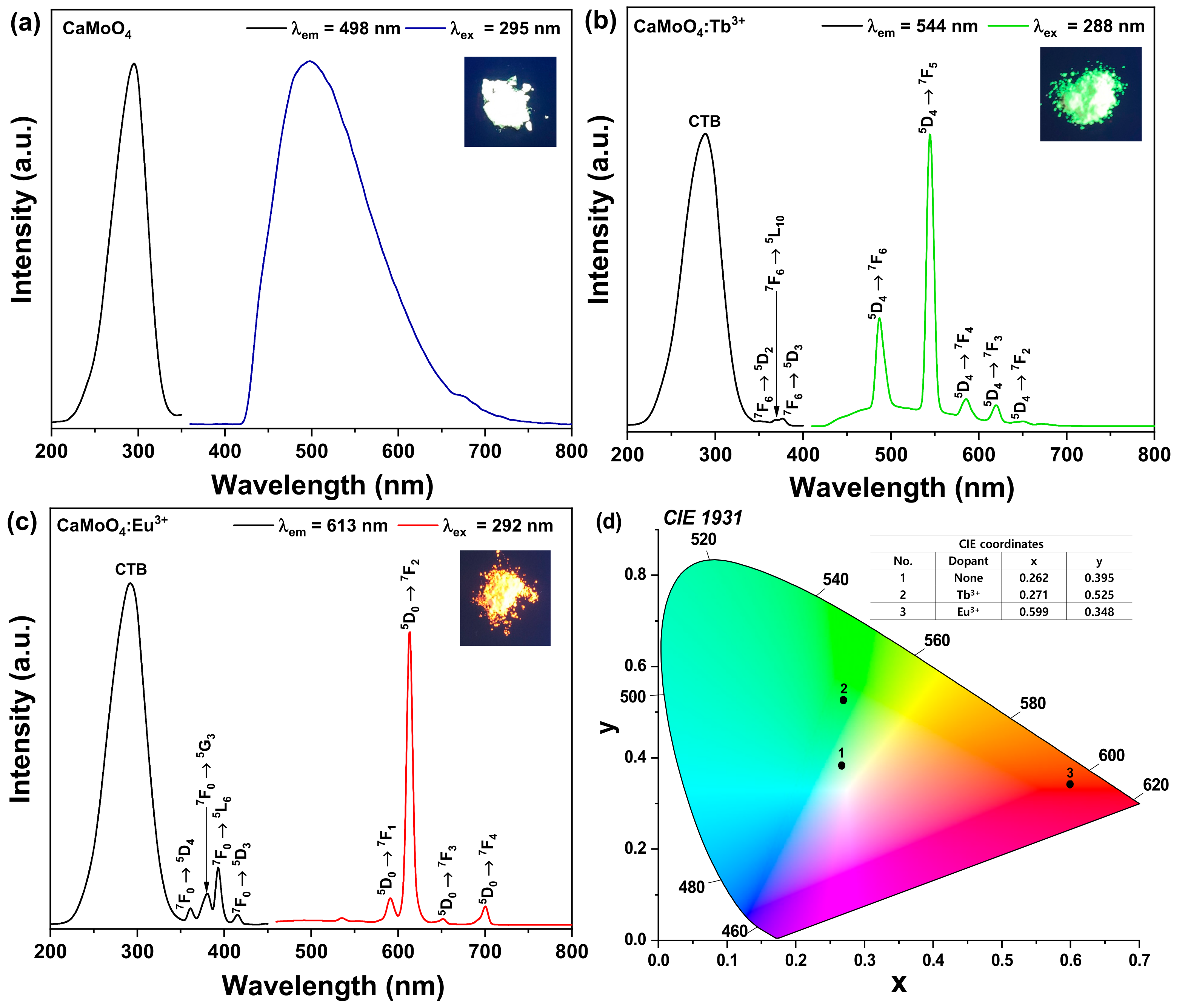
The photoluminescence excitation (PLE) and photoluminescence (PL) spectra of the CaMoO4 phosphor are shown in Figure 5a. The PLE spectrum (black line) was monitored at an emission wavelength at 498 nm. This spectrum showed a broad peak centered at 295 nm, which arose due to the Mo–O charge-transfer band [26]. The PL spectrum (blue line) was monitored at an excitation wavelength at 295 nm, showing a broad band around 498 nm, attributable to the intrinsic luminescence of the host lattice. Figure 5b shows the PLE spectrum (black line) of the CaMoO4:Tb3+ phosphor monitored at an emission wavelength of 544 nm. The PLE spectrum of the CaMoO4:Tb3+ phosphors contained a charge transfer state (CTB) and f−f transitions due to the presence of Tb3+ ions [27]. CTB includes a broad band in the wavelength range of 220–320 nm. This band could arise due to the Mo-O and Tb–O charge transfer. The f−f transitions associated with a few weak peaks were located at 350, 369, and 376 nm, which were attributed to the 7F6 → 5D2, 7F6 → 5L10, and 7F6 → 5D3 transitions of the Tb3+ ions, respectively. The PL spectrum (green line) was observed for the excitation wavelength of 288 nm, stemming from the Tb–O CTB. The emission spectra contained five peaks centered at 486, 544, 586, 620, and 650 nm wavelengths corresponding to the 5D4 → 7F6, 5D4 → 7F5, 5D4 → 7F4, 5D4 → 7F3, and 5D4 → 7F2 transitions [28]. These transitions were well known characteristic transitions of Tb3+ ions. Among the above five types of emission spectra, the intensity of the green emission spectrum due to the 5D4 → 7F5 (544 nm) magnetic dipole transition was the strongest, and this emission intensity was the strongest due to the 5D4 → 7F6 (486 nm) electric dipole transition of the Tb3+ ion [29]. It was 2.69 times that of the blue emission intensity. From this result, it can be confirmed that the Tb3+ ion located in the host crystal was located at an inversion symmetry site. Figure 5c shows the results of the PLE (black line) and PL (red line) spectra when measured in the CaMoO4:Eu3+ phosphor powder. For the CaMoO4:Eu3+ phosphor powder controlled to an emission wavelength of 613 nm, two types of PLE spectra were observed. One type of absorption signal was an absorption spectrum by CTB generated between Mo-O ions with a wide bandgap over the region of 220–320 nm and a peak at 292 nm, and the other type of absorption signal is at 320–450 nm. Observed in the wavelength region, these absorption signals were 4f−4f transition signals of Eu3+ ions [30]. The absorption spectra observed at the peaks at 361, 381, 393, and 415 nm corresponded to the 7F0 → 5D4, 7F0 → 5G3, 7F0 → 5L6, and 7F0 → 5D3 transition signals of the Eu3+ ions located in the host crystal [31]. The emission spectrum of the phosphor was measured by exciting the phosphor powder with a wavelength of 292 nm, showing the strongest absorption intensity. The phosphor powder was composed of an emission spectrum with the strongest emission intensity with a peak at a wavelength of 613 nm, a peak emission spectrum at 590 nm with a relatively weak emission intensity, and an emission spectrum with peaks at 651 nm and 700 nm. Here, 613 nm was the signal induced by the 5D0 → 7F2 electric dipole transition, 590 nm was the 5D0 → 7F1 magnetic dipole transition, and the two red emission spectra (651 and 700 nm) were the 5D0 → 7F3 and 5D0 → 7F4 electric dipole signals [32]. In this experiment, because the intensity of the red emission (613 nm) spectrum stemming from the 5D0 → 7F2 electric dipole transition was 10.9 times greater than the intensity of the orange emission (590 nm) from the 5D0 → 7F1 magnetic dipole transition, Eu3+ ions in the host lattice were found to be located at the sites of inversion symmetry, not inversion symmetry [33]. Color coordinates were an important factor when evaluating the performance of a phosphor, and a proper understanding of color purity is important when applying these phosphors in the lighting industry. Figure 5d shows the CIE (Commission Internationale de L’Eclairage 1931) color coordinates of the CaMoO4 phosphor powder doped with different activator ions. The CIE color coordinates of the phosphor powder were investigated based on the data of the emission spectrum. The numbers shown in Figure 5d indicate the color coordinates of the activator ions No. 1 CaMoO4 (0.262, 0.395), No. 2 CaMoO4:Tb3+ (0.271, 0.525), and No. 3 CaMoO4:Eu3+ (0.599, 0.348) phosphors.

Figure 5.
PLE and PL spectra of (a) CaMoO4, (b) CaMoO4:Tb3+, (c) CaMoO4:Eu3+, and (d) CIE coordination.
In addition, we measured the time-resolved photoluminescence (TRPL) for the luminescence dynamics of CaMoO4 and CaMoO4:RE3+, as shown in Figure 6a. After an analysis of the TRPL [34,35], the excitation wavelength was found to be 315 nm. The wavelengths used for the analysis were those of CaMoO4, CaMoO4:Tb3+, and CaMoO4:Eu3+ emitted at 498 nm, 544 nm, and 613 nm, respectively. Figure 6b shows that the average decay time (τavg) elapsed slowly. It is believed that the light energy received from the host is transferred to the doped rare-earth ions as an activator and that the light emission lifetime of the rare-earth-doped sample is longer than that of the undoped sample due to the mechanism used by the phosphor to emit light (CaMoO4 = Non, CaMoO4:Tb3+ = 431 μs, CaMoO4:Eu3+ = 654 μs). Zhu et al. observed changes in properties according to the changes in structure, surface shape, and pores according to the doping amount of the carbon material when manufacturing a composite in which a carbon material and a conductive material were mixed. It was announced that the characteristics of a supercapacitor were strengthened by utilizing the characteristics changed by the doping material [36]. In this study, it was found that the structure, particle size, and surface shape of CaMoO4 were changed by the addition of rare earth, and the luminescence properties were strengthened. Table S1 compares the properties of CaMoO4 phosphors doped with rare earths synthesized by other methods. It can be seen that the synthesis method presented in this work is easy and can be synthesized at room temperature without additional heat treatment, and the luminescence properties are strong.
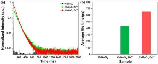
Figure 6.
(a) Time-resolved PL and (b) average decay time.
3.3. Flexible Composite with a UV-LED Color Filter Applied for Anti-Counterfeiting
The composite produced by mixing the synthesized phosphor and PDMS was difficult to identify with the naked eye, as all three samples (CaMoO4, CaMoO4:Tb3+, and CaMoO4:Eu3+) were white squares under typical everyday lighting. However, in the UV lamp, it was possible to distinguish between blue, green, and red by realizing the unique color of the phosphor, and it showed flexibility by being easily bent with a finger (Figure 7a). In addition, the same composite was placed on the UV-LED chip and power was supplied. As in the case of a UV lamp, it showed the unique emission color of the phosphor, and when the actual emission wavelength was measured using an LED photometer, the same result found with the previous PL spectrum was shown here as well (Figure 7b). Ink made of phosphor powder synthesized by doping with rare-earth ions (CaMoO4:Tb3+ and CaMoO4:Eu3+) was applied to a bank note with a brush. In daylight, it could not be found with the naked eye, though green and red luminescence could be confirmed with a UV lamp (Figure 7c). This suggests that the flexible composite produced in this study could be used as a UV-LED color filter and that the ink produced using a phosphor could be applied to help prevent counterfeiting.
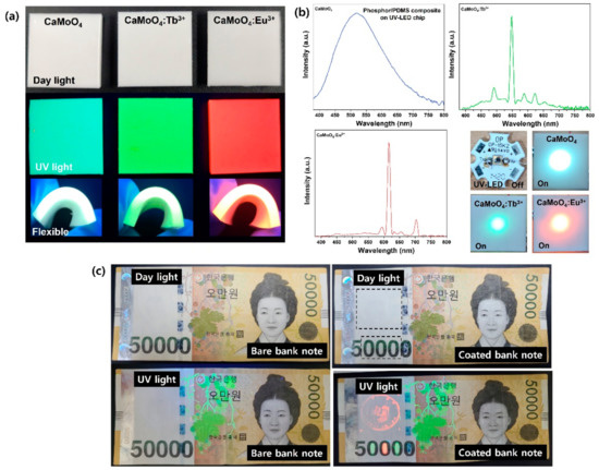
Figure 7.
(a) Phosphors-PDMS composite under daylight and UV light. (b) Composite on UV-LED chip and a detected LED photometer. (c) Anti-counterfeiting ink painted on a banknote.
4. Conclusions
At room temperature, crystalline CaMoO4 and rare-earth-ion-doped CaMoO4:Tb3+ and CaMoO4:Eu3+ powders were synthesized via a co-precipitation method. The synthesized powder had a tetragonal structure with the (112) phase as the main peak, according to the XRD analysis. As the rare-earth ions were doped, a change in the lattice constant was observed, and calculations showed that the doped rare-earth ion was doped with about 1.557 × 10¹⁹ RE atoms/cm3 in the host CaMoO4 lattice. When the powder synthesized by FE-SEM was observed, about 50 nm-sized particles of CaMoO4 were agglomerated to form particles approximately 3 μm in size. In the XPS analysis, changes in the binding energy of Ca 2p, Mo 3d, and O 1s were observed as the rare-earth ions were added, and the binding energy peaks of Tb 3d and Eu 3d were observed to confirm that rare-earth ions were doped. The synthesized powder had a tetragonal structure with the main diffraction peak in the (112) phase. When CaMoO4 was excited at 295 nm, it showed a central peak of 498 nm and light emission in a wide range of 420 to 700 nm. Rare-earth-ion-doped CaMoO4:Tb3+ was excited at 288 nm and green light emission was observed at 544 nm, and CaMoO4:Eu3+ was excited at 292 nm and red light emission was observed at 613 nm. To take advantage of the light-emitting characteristics, a flexible composite was manufactured and a color filter that can be used for UV-LEDs was manufactured. In addition, it was suggested that an ink that could be checked only by UV light could be produced and applied to banknotes so as to prevent counterfeiting.
Supplementary Materials
The following supporting information can be downloaded at: https://www.mdpi.com/article/10.3390/ma15062078/s1. Figure S1: SEM-EDS mapping data of CaMoO4:Tb3+ (up) and CaMoO4:Eu3+ (down); Table S1: The comparison among similar literature.
Funding
This research received no external funding.
Institutional Review Board Statement
Not applicable.
Informed Consent Statement
Not applicable.
Data Availability Statement
The data presented in this study are available upon request from the corresponding author.
Conflicts of Interest
The author declares no conflict of interest.
References
- Takahashi, H.; Matsushima, Y. Investigation on Luminescent Properties of Rare Earth Doped Mullite Phosphors and the Occupation Site of the Doped Rare Earths. J. Electrochem. Soc. 2019, 166, B3209–B3217. [Google Scholar] [CrossRef]
- Wang, X.; Xu, J.; Yu, J.; Bu, Y.; Marques-Hueso, J.; Yan, X. Morphology control, spectrum modification and extended optical applications of rare earth ion doped phosphors. Phys. Chem. Chem. Phys. PCCP 2020, 22, 1512–15162. [Google Scholar] [CrossRef]
- Secu, M.; Secu, C.; Bartha, C. Optical Properties of Transparent Rare-Earth Doped Sol-Gel Derived Nano-Glass Ceramics. Materials 2021, 14, 6871. [Google Scholar] [CrossRef]
- Verma, S.; Verma, K.; Kumar, D.; Chaudhary, B.; Som, S.; Sharma, V.; Kumar, V.; Swart, H.C. Recent advances in rare earth doped alkali-alkaline earth borates for solid state lighting applications. Phys. B Condens. Matter 2018, 535, 106–113. [Google Scholar] [CrossRef]
- Wang, M.; Liu, J.; Zhang, Y.; Hou, W.; Wu, X.; Xu, S. Two-phase solvothermal synthesis of rare-earth doped NaYF4 upconversion fluorescent nanocrystals. Mater. Lett. 2009, 63, 325–327. [Google Scholar] [CrossRef]
- Maia, A.S.; Stefani, R.; Kodaira, C.A.; Felinto, M.C.F.C.; Teotonio, E.E.S.; Brito, H.F. Luminescent nanoparticles of MgAl2O4:Eu, Dy prepared by citrate sol–gel method. Opt. Mater. 2008, 31, 440–444. [Google Scholar] [CrossRef]
- Jain, U. Structural and Photoluminescence Characterization of MgAl2O4:Eu Phosphor Synthesized by Combustion Method. Int. J. Adv. Res. 2017, 5, 1887–1890. [Google Scholar] [CrossRef] [Green Version]
- Wu, H.; Yang, J.; Wang, X.; Gan, S.; Li, L. Solvent directed morphologies and enhanced luminescent properties of BaWO4:Tm3+, Dy 3+ for white light emitting diodes. Solid State Sci. 2018, 79, 85–92. [Google Scholar] [CrossRef]
- Botelho, G.; Nogueira, I.C.; Moraes, E.; Longo, E. Study of structural and optical properties of CaMoO4 nanoparticles synthesized by the microwave-assisted solvothermal method. Mater. Chem. Phys. 2016, 183, 110–120. [Google Scholar] [CrossRef] [Green Version]
- Oliveira, F.K.F.; Oliveira, M.C.; Gracia, L.; Tranquilin, R.L.; Paskocimas, C.A.; Motta, F.V.; Longo, E.; Andrés, J.; Bomio, M.R.D. Experimental and theoretical study to explain the morphology of CaMoO4 crystals. J. Phys. Chem. Solids 2018, 114, 141–152. [Google Scholar] [CrossRef]
- Kim, M.; Huh, Y. Synthesis and optical properties of CaMoO4:Eu3+, Na+ nanophosphors and a transparent CaMoO4:Eu3+, Na+ suspension. Opt. Mater. 2012, 35, 263–267. [Google Scholar] [CrossRef]
- Wang, Y.; Ma, J.; Tao, J.; Zhu, X.; Zhou, J.; Zhao, Z.; Xie, L.; Tian, H. Low temperature synthesis of CaMoO4 nanoparticles. Ceram. Int. 2007, 33, 693–695. [Google Scholar] [CrossRef]
- Lim, C.S. Cyclic MAM synthesis and upconversion photoluminescence properties of CaMoO4:Er3+/Yb3+ particles. Mater. Res. Bull. 2012, 47, 4220–4225. [Google Scholar] [CrossRef]
- Xia, Z.; Chen, D. Synthesis and Luminescence Properties of BaMoO4:Sm3+ Phosphors. J. Am. Ceram. Soc. 2010, 93, 1397–1401. [Google Scholar] [CrossRef]
- Pereira, P.F.S.; Nogueira, I.C.; Longo, E.; Nassar, E.J.; Rosa, I.L.V.; Cavalcante, L.S. Rietveld refinement and optical properties of SrWO4:Eu3+ powders prepared by the non-hydrolytic sol-gel method. J. Rare Earths 2015, 33, 113. [Google Scholar] [CrossRef]
- Liu, S.; Kang, L.; Hu, J.; Jung, E.; Zhang, J.; Jun, S.C.; Yamauchi, Y. Unlocking the Potential of Oxygen-Deficient Copper-Doped Co3O4 Nanocrystals Confined in Carbon as an Advanced Electrode for Flexible Solid-State Supercapacitors. ACS Energy Lett. 2021, 6, 3011. [Google Scholar] [CrossRef]
- Thongtem, T.; Kungwankunakorn, S.; Kuntalue, B.; Phuruangrat, A.; Thongtem, S. Luminescence and absorbance of highly crystalline CaMoO4, SrMoO4, CaWO4 and SrWO4 nanoparticles synthesized by co-precipitation method at room temperature. J. Alloys Compd. 2010, 506, 475–481. [Google Scholar] [CrossRef]
- Kacher, J.; Landon, C.; Adams, B.L.; Fullwood, D. Bragg’s Law diffraction simulations for electron backscatter diffraction analysis. Ultramicroscopy 2009, 109, 1148–1156. [Google Scholar] [CrossRef] [PubMed]
- Kaur, P.; Khanna, A.; Singh, M.N.; Sinha, A.K. Structural and optical characterization of Eu and Dy doped CaWO4 nanoparticles for white light emission. J. Alloys Compd. 2020, 834, 154804. [Google Scholar] [CrossRef]
- He, P.Y.; Zhang, Y.J.; Chen, H.; Liu, L.C. Development of an eco-efficient CaMoO4/electroconductive geopolymer composite for recycling silicomanganese slag and degradation of dye wastewater. J. Clean. Prod. 2019, 208, 1476–1487. [Google Scholar] [CrossRef]
- Gou, Y.; Liu, Q.; Shi, X.; Asiri, A.; Hu, J.; Sun, X. CaMoO4 nanosheet array for efficient and durable water oxidation electrocatalysis under alkaline conditions. RSC Chem. Commun. 2018, 54, 5066. [Google Scholar] [CrossRef] [PubMed]
- Dutta, S.; Som, S.; Kunti, A.K.; Kumar, V.; Sharma, S.K.; Swart, H.C.; Visser, H.G. Structural and luminescence responses of CaMoO4 nano phosphors synthesized by hydrothermal route to swift heavy ion irradiation: Elemental and spectral stability. Acta Mater. 2017, 124, 109–119. [Google Scholar] [CrossRef]
- Gupta, S.K.; Sahu, M.; Ghosh, P.S.; Tyagi, D.; Saxena, M.K.; Kadam, R.M. Energy transfer dynamics and luminescence properties of Eu3+ in CaMoO4 and SrMoO4. Dalton Trans. Int. J. Inorg. Chem. 2015, 44, 18957–18969. [Google Scholar] [CrossRef]
- Bharat, L.K.; Raju, G.S.R.; Yu, J.S. Red and green colors emitting spherical-shaped calcium molybdate nanophosphors for enhanced latent fingerprint detection. Sci. Rep. 2017, 7, 11571. [Google Scholar] [CrossRef] [PubMed]
- Singh, B.P.; Maheshwary, M.; Ramakrishna, P.V.; Singh, S.; Sonu, V.K.; Singh, S.; Singh, P.; Bahadur, A.; Singh, R.A.; Rai, S.B. Improved photo-luminescence behaviour of Eu3+ activated CaMoO4 nanoparticles via Zn2+ incorporation. RSC Adv. 2015, 5, 55977–55985. [Google Scholar] [CrossRef]
- Ryu, J.H.; Choi, B.G.; Yoon, J.-W.; Shim, K.B.; Machi, K.; Hamada, K. Synthesis of nanoparticles by pulsed laser ablation in deionized water and optical properties. J. Lumin. 2007, 124, 67–70. [Google Scholar] [CrossRef]
- Ansari, A.A.; Parchur, A.K.; Alam, M.; Azzeer, A. Structural and photoluminescence properties of Tb-doped CaMoO4 nanoparticles with sequential surface coatings. Mater. Chem. Phys. 2014, 147, 715–721. [Google Scholar] [CrossRef]
- Ding, Y.; Liu, J.; Zhu, Y.; Nie, S.; Wang, W.; Shi, J.; Miu, Y. Brightly luminescent and color-tunable CaMoO4:RE3+ nanofibers synthesized through a facile route for efficient light-emitting diodes. J. Mater. Sci. 2018, 53, 4861. [Google Scholar] [CrossRef]
- Parchur, A.K.; Prasad, A.I.; Ansari, A.A.; Rai, S.B.; Ningthoujam, R.S. Luminescence properties of Tb3+-doped CaMoO4 nanoparticles: Annealing effect, polar medium dispersible, polymer film and core–shell formation. Dalton Trans. Int. J. Inorg. Chem. 2012, 41, 11032–11045. [Google Scholar] [CrossRef]
- Liu, J.; Lian, H.; Shi, C. Improved optical photoluminescence by charge compensation in the phosphor system CaMoO4:Eu3+. Opt. Mater. 2007, 29, 1591–1594. [Google Scholar] [CrossRef]
- Ansari, A.A.; Parchur, A.K.; Alam, M.; Azzeer, A. Effect of surface coating on optical properties of Eu3+-doped CaMoO4 nanoparticles. Spectrochim. Acta A Mol. Biomol. Spectrosc. 2014, 131, 30–36. [Google Scholar] [CrossRef] [PubMed]
- Tranquilin, R.L.; Lovisa, L.X.; Almeida, C.R.R.; Paskocimas, C.A.; Li, M.S.; Oliveira, M.C.; Gracia, L.; Andres, J.J.; Longo, E.; Motta, F.V.; et al. Understanding the White-Emitting CaMoO4 Co-Doped Eu3+, Tb3+, and Tm3+ Phosphor through Experiment and Computation. J. Phys. Chem. C 2019, 123, 18536. [Google Scholar] [CrossRef]
- Letswalo, M.L.A.; Reddy, L.; Balakrishna, A.; Swart, H.C.; Ntwaeaborwa, O.M. Influence of SO42− anionic group substitution on the enhanced photoluminescence behaviour of red emitting CaMoO4:Eu3+ phosphor. J. Alloys Compd. 2021, 854, 157022. [Google Scholar] [CrossRef]
- Chance, B.; Leigh, J.S.; Miyake, H.; Smith, D.S.; Nioka, S.; Greenfeld, R.; Finander, M.; Kaufmann, K.; Levy, W.; Young, M. Comparison of Time-Resolved and -Unresolved Measurements of Deoxyhemoglobin in Brain. Proc. Natl. Acad. Sci. USA 1988, 85, 4971–4975. [Google Scholar] [CrossRef] [PubMed] [Green Version]
- Chukhutsina, V.U.; Holzwarth, A.R.; Croce, R. Time-resolved fluorescence measurements on leaves: Principles and recent developments. Photosynth. Res. 2019, 140, 355–369. [Google Scholar] [CrossRef] [PubMed]
- Zhu, Z.; Wang, Z.; Ba, Z.; Li, X.; Dong, J.; Fang, Y.; Zhang, Q.; Zhao, X. 3D MXene-holey graphene hydrogel for supercapacitor with superior energy storage. J. Energy Storage 2022, 47, 103911. [Google Scholar] [CrossRef]


Publisher’s Note: MDPI stays neutral with regard to jurisdictional claims in published maps and institutional affiliations. |
© 2022 by the author. Licensee MDPI, Basel, Switzerland. This article is an open access article distributed under the terms and conditions of the Creative Commons Attribution (CC BY) license (https://creativecommons.org/licenses/by/4.0/).