
Turning Copper and Aluminum Alloys with Natural Rocks as Cutting Tools


Abstract
:1. Introduction
2. Materials and Methods
2.1. Fabrication and Characterization of Cutting Tools Made of Natural Rocks
2.2. Turning Operations
3. Results and Discussion
3.1. Surface Roughness and Cutting Edge Properties of the Rock Inserts
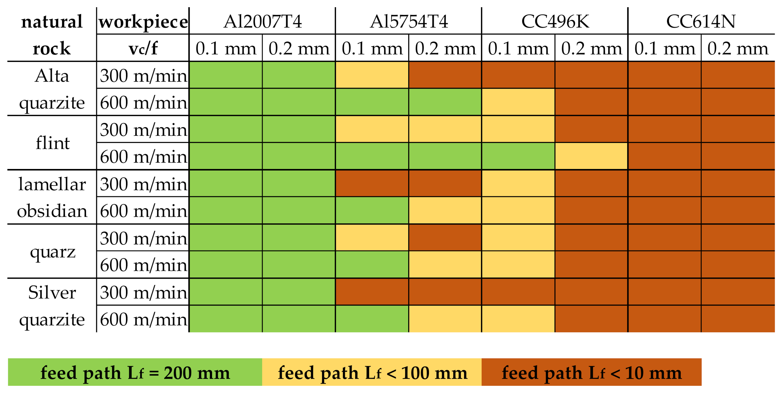
3.2. Application Area of Natural Rocks as Cutting Material
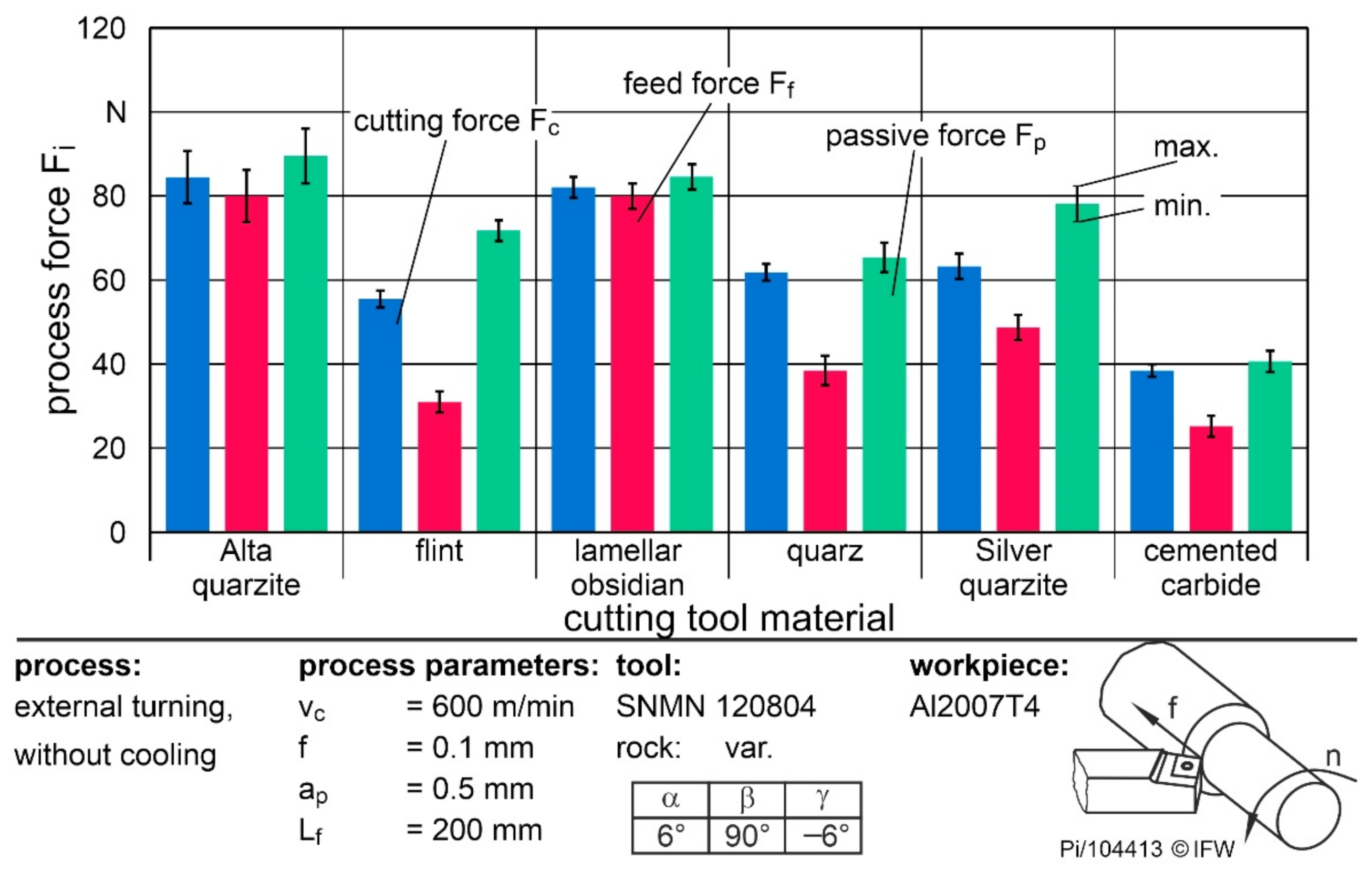
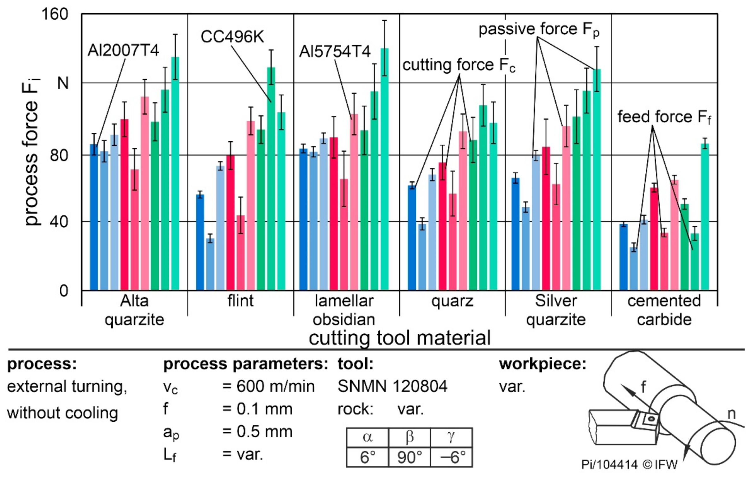
3.3. Tool Loads during Cutting with Natural Rocks
4. Conclusions
- Cutting edge roughness and cutting edge microgeometry after grinding vary depending on the rock properties. The resulting cutting edge roundings are up to four times higher than for a conventional cemented carbide insert.
- Due to the influence of cutting edge microgeometry on the operational behavior of cutting inserts, the application of cutting edge preparation steps after grinding must be considered to achieve higher cutting edge quality.
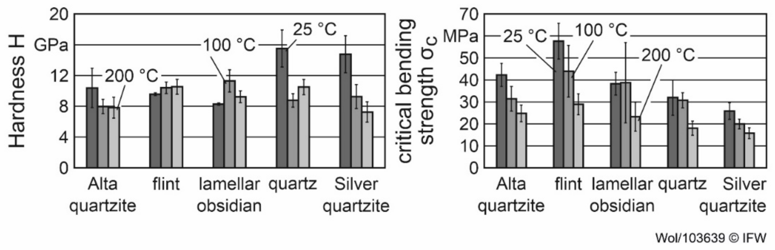
- Flint and quartz are well suited for machining low-adhesion materials with high cutting speeds due to their hardness and bending strength.
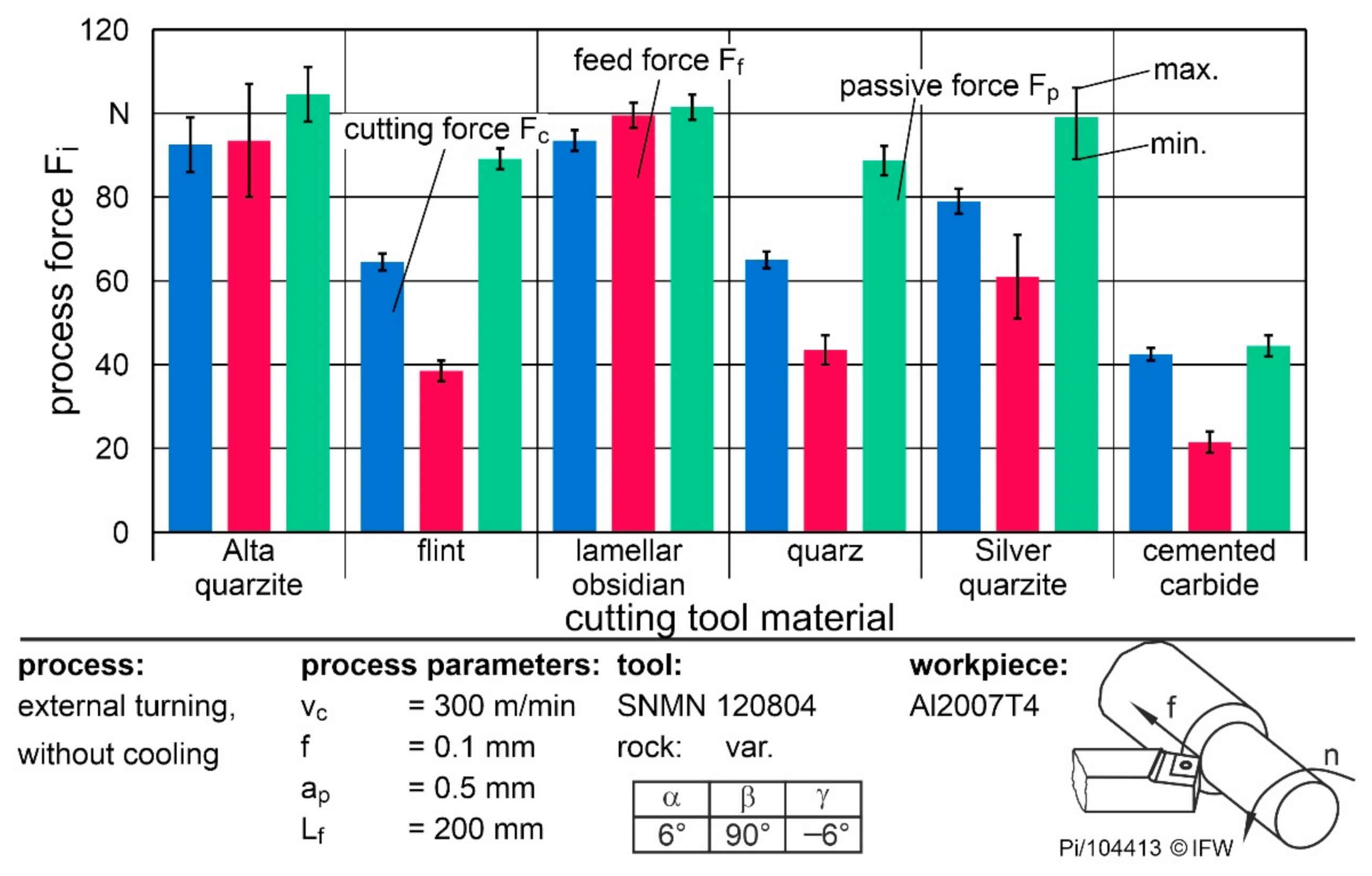
- The influences of feed rate and cutting speed on the cutting forces show the same tendency as conventional cutting materials.
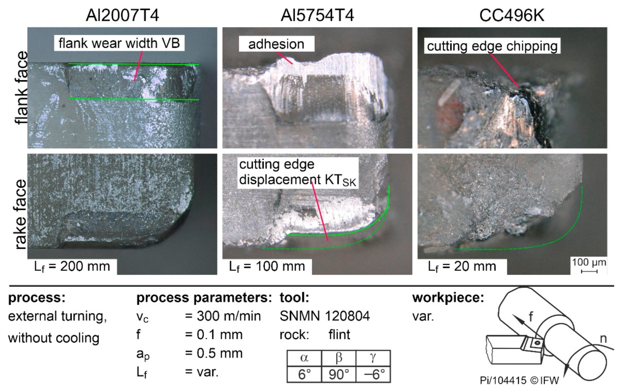
- The large cutting edge microgeometry and surface roughness of the rocks lead to strong material accumulations and high process forces when machining adhesive materials.
Author Contributions
Funding
Institutional Review Board Statement
Informed Consent Statement
Data Availability Statement
Conflicts of Interest
References
- Furberg, A.; Arvidsson, R.; Molander, S. Enviromental life cycle assessment of cemented carbide (WC-Co) production. J. Clean. Prod. 2019, 209, 1126–1138. [Google Scholar] [CrossRef]
- Werner, A.B.T.; Sinclair, W.D.; Amey, E.B. International Strategic Mineral Issues Summary Report—Tungsten; U.S. Geological Survey Circular 930-O: Reston, VA, USA, 2014.
- Gislev, M.; Grohol, M. Report on Critical Raw Materials and the Circular Economy; European Commission: Brussels, Belgium, 2018. [Google Scholar]
- European Union Project. Flintstone 2020 Next Generation of Superhard Non-CRM Materials and Solutions in Tooling; Lund University: Lund, Sweden, 2017. [Google Scholar]
- Hrechuk, A.; Johansson, D.; Bushlya, V.; Devin, L.; Ståhl, J.-E. Application of Colding tool life equation on the drilling fiber reinforcement polymers. Procedia Manuf. 2018, 25, 302–308. [Google Scholar] [CrossRef]
- Denkena, B.; Breidenstein, B.; Krödel, A.; Bergmann, B.; Picker, T.; Wolters, P. Suitability of natural rocks as materials for cutting tools. SN Appl. Sci. 2021, 4, 2. [Google Scholar] [CrossRef]
- Wolters, P.; Picker, T.; Breidenstein, B.; Krödel, A.; Denkena, B. Application of natural rocks in cutting aluminum. In Production at the Leading Edge of Technology. WGP 2021; Behrens, B.A., Brosius, A., Drossel, W.G., Hintze, W., Ihlenfeldt, S., Nyhuis, P., Eds.; Lecture Notes in Production Engineering; Springer: Cham, Switzerland, 2021; pp. 230–238. [Google Scholar]
- Denkena, B.; Boehnke, D.; Bockhorst, J. Thin tools for the high speed cutting of granite. Int. J. Abras. Technol. 2019, 2, 173–183. [Google Scholar] [CrossRef]
- Almasi, S.N.; Bagherpour, R.; Mikaeil, R.; Ozcelik, Y. Analysis of bead wear in diamond wire sawing considering the rock properties and production rate. Bull. Eng. Geol. Environ. 2017, 76, 1593–1607. [Google Scholar] [CrossRef]
- Miedema, S.A. The Delft Sand, Clay & Rock Cutting Model, 1st ed.; IOS Press: Amsterdam, The Netherlands, 2014. [Google Scholar]
- Richard, T.; Dagrain, F.; Poyol, E.; Detournay, E. Rock strength determination from scratch tests. Eng. Geol. 2012, 147–148, 91–100. [Google Scholar] [CrossRef]
- Garner, N. Cutting Action of a Single Diamond Under Simulated Borehole Conditions. J. Pet. Technol. 1967, 19, 937–942. [Google Scholar] [CrossRef]
- Nishimatsu, Y. The mechanics of rock cutting. Int. J. Rock Mech. Min. Sci. Geomech. Abstr. 1972, 9, 261–270. [Google Scholar] [CrossRef]
- Johansson, E. Technological Properties of Rock Aggregates. Ph.D. Thesis, Luleå University of Technology, Luleå, Sweden, 2011. [Google Scholar]
- Meng, F.; Wong, L.N.Y.; Zhou, H. Rock brittleness indices and their applications to different fields of rock engineering: A review. J. Rock Mech. Geotech. Eng. 2021, 13, 221–247. [Google Scholar] [CrossRef]
- Denkena, B.; Grove, T.; Bremer, I.; Behrens, L. Design of bronze-bonded grinding wheel properties. CIRP Ann. 2016, 65, 333–336. [Google Scholar] [CrossRef]
- Denkena, B.; Breidenstein, B.; Bergmann, B.; Wolters, P. Investigation of the material separation behaviour of rocks using scratch tests for the design of tool grinding processes. Springer Nat. Appl. Sci. 2022; submitted. [Google Scholar]
- Denkena, B.; Biermann, D. Cutting edge geometries. CIRP Ann.-Manuf. Technol. 2014, 63, 631–653. [Google Scholar] [CrossRef]
- Bergmann, B. Grundlagen zur Auslegung von Schneidkantenverrundungen. Ph.D. Thesis, Leibniz University Hannover, Hannover, Germany, 2017. [Google Scholar]
- Bergmann, B.; Denkena, B.; Grove, T.; Picker, T. Chip formation of rounded cutting edges. Int. J. Precis. Eng. Manuf. 2019, 20, 37–44. [Google Scholar] [CrossRef]


| Workpiece | Tensile Strength [MPa] | Young’s Modulus [GPa] | Yield Strength [MPa] | Hardness [GPa] | Density [g/cm3] | Thermal Conductivity [W/m·K] |
|---|---|---|---|---|---|---|
| Al2007T4 | 340 | 73 | 200 | 0.98 | 2.85 | 145 |
| Al5754T4 | 230 | 70 | 80 | 0.52 | 2.67 | 150 |
| CC496K | 200 | 82 | 90 | 0.67 | 9.20 | 59 |
| CW614N | 360 | 96 | 350 | 0.93 | 8.46 | 113 |
| Rock | Cutting Edge Segment on Flank Face Sα [µm] | Cutting Edge Segment on Rake Face Sγ [µm] | [µm] |
|---|---|---|---|
| Alta quartzite | 30.9 ± 2.1 | 49.6 ± 6.3 | 40.2 ± 3.8 |
| flint | 23.3 ± 5.5 | 28.0 ± 11.8 | 25.6 ± 8.5 |
| lamellar obsidian | 22.7 ± 5.6 | 36.7 ± 11.3 | 29.7 ± 8.0 |
| quartz | 31.7 ± 12.1 | 39.3 ± 14.4 | 35.5 ± 12.9 |
| silver quartzite | 33.4 ± 2.5 | 45.6 ± 11.1 | 39.5 ± 6.4 |
| cemented carbide | 9.4 ± 1.8 | 11.0 ± 2.6 | 10.2 ± 2.2 |
Publisher’s Note: MDPI stays neutral with regard to jurisdictional claims in published maps and institutional affiliations. |
© 2022 by the authors. Licensee MDPI, Basel, Switzerland. This article is an open access article distributed under the terms and conditions of the Creative Commons Attribution (CC BY) license (https://creativecommons.org/licenses/by/4.0/).
Share and Cite
Breidenstein, B.; Denkena, B.; Bergmann, B.; Wolters, P.; Picker, T. Turning Copper and Aluminum Alloys with Natural Rocks as Cutting Tools. Materials 2022, 15, 2187. https://doi.org/10.3390/ma15062187
Breidenstein B, Denkena B, Bergmann B, Wolters P, Picker T. Turning Copper and Aluminum Alloys with Natural Rocks as Cutting Tools. Materials. 2022; 15(6):2187. https://doi.org/10.3390/ma15062187
Chicago/Turabian StyleBreidenstein, Bernd, Berend Denkena, Benjamin Bergmann, Philipp Wolters, and Tobias Picker. 2022. "Turning Copper and Aluminum Alloys with Natural Rocks as Cutting Tools" Materials 15, no. 6: 2187. https://doi.org/10.3390/ma15062187
APA StyleBreidenstein, B., Denkena, B., Bergmann, B., Wolters, P., & Picker, T. (2022). Turning Copper and Aluminum Alloys with Natural Rocks as Cutting Tools. Materials, 15(6), 2187. https://doi.org/10.3390/ma15062187