
Characteristics of Vibrating Fluidization and Transportation for Al2O3 Powder

 ,
,
Abstract
:1. Introduction
2. Experiment
2.1. Materials
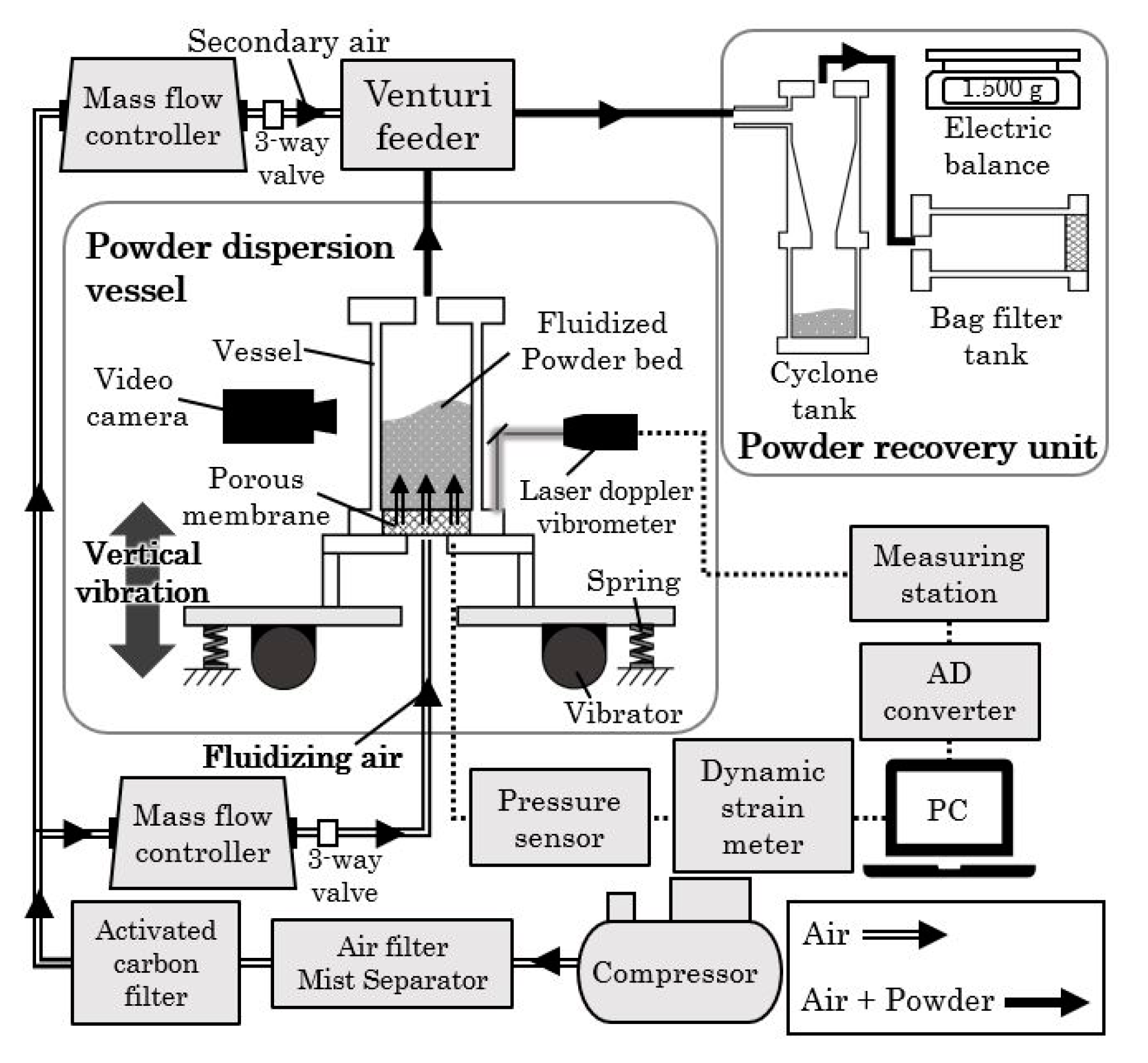
2.2. Test Equipment
2.3. Experimental Conditions
2.4. Experimental Method
2.4.1. Fluidization Experiment
2.4.2. Powder Transportation Experiment
3. Results
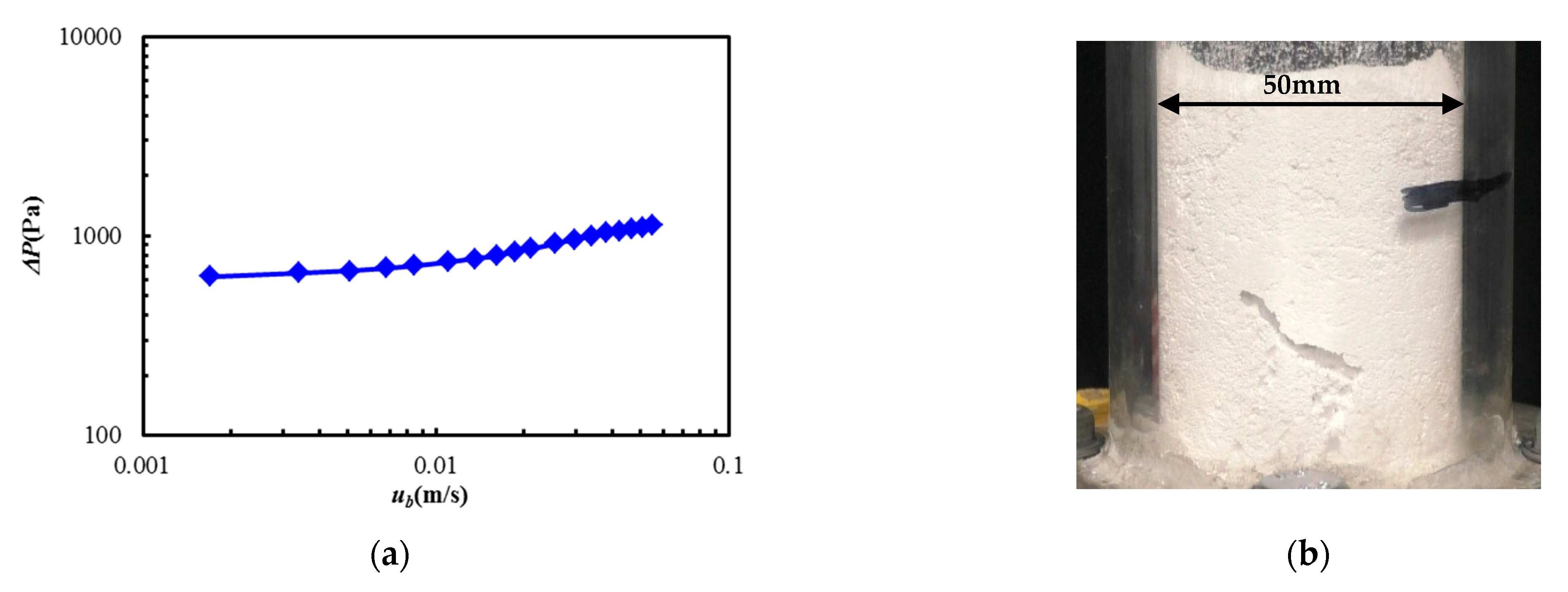
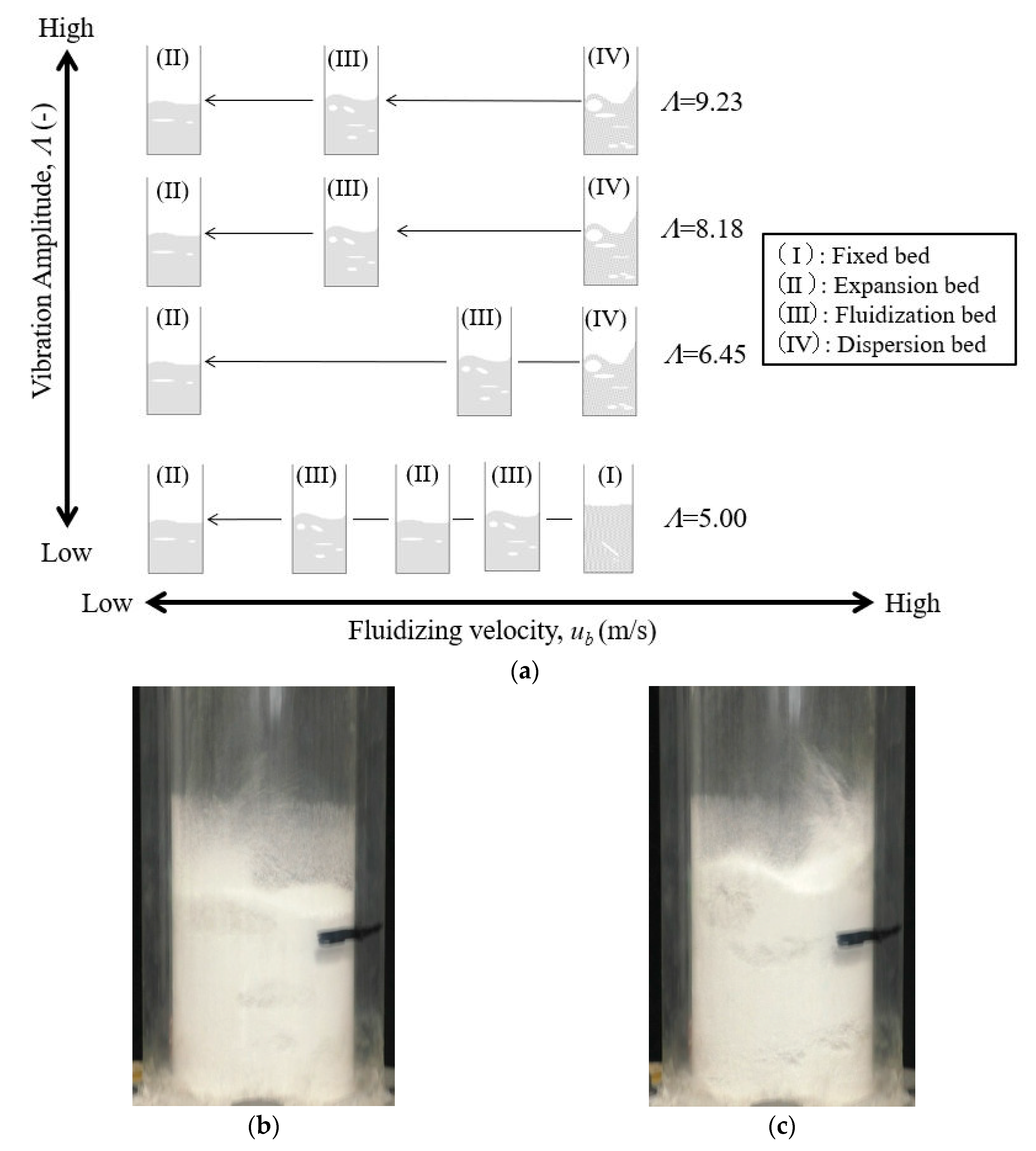
3.1. Fluidization Characteristics
- (I)
- Fixed bed: The powder bed was close to a stationary state, and agitation or expansion due to the vibration and fluidization of air was not observed.
- (II)
- Expansion bed: Expansion of the powder bed was confirmed by vibrating fluidization. There were no bubbles in the powder bed.
- (III)
- Fluidized bed: The powder bed was fluidized, and air bubbles were also observed, as shown in Figure 8b.
- (IV)
- Dispersion bed: The powder bed was intensely fluidized, and the powder was dispersed toward the upside of the powder dispersion vessel, as shown in Figure 8c.
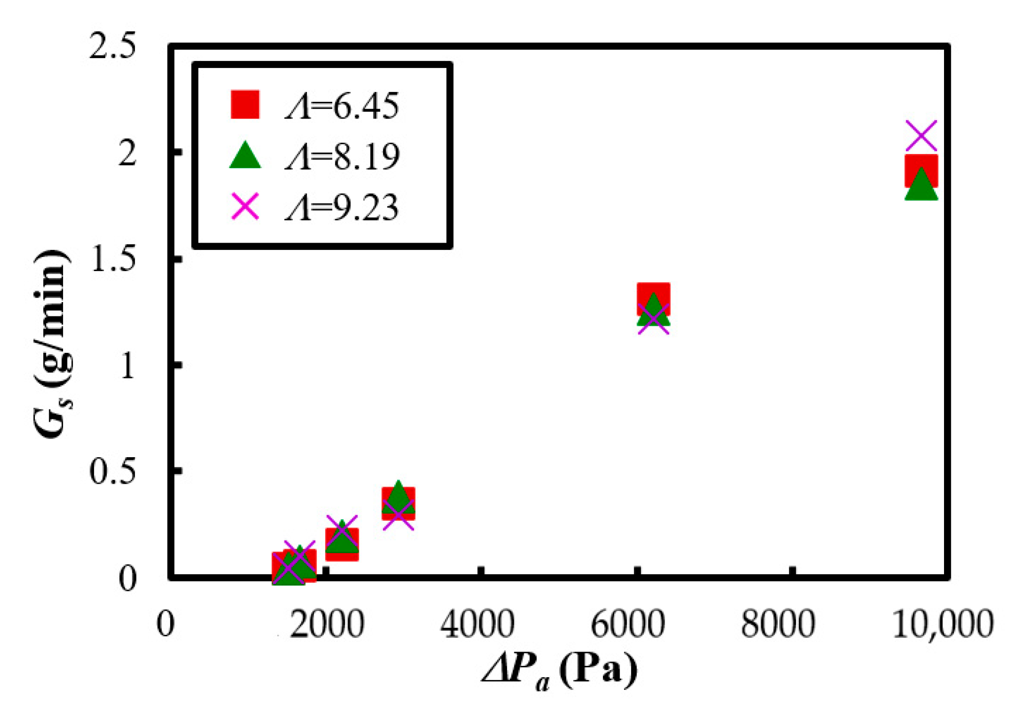
3.2. Powder Transportation Characteristics
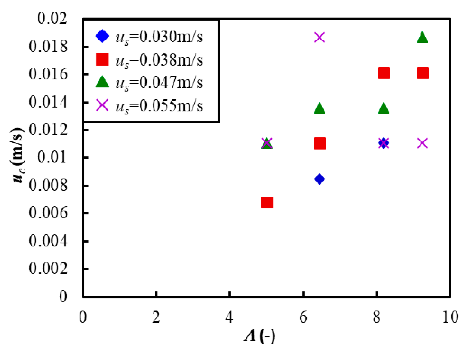
3.3. Dispersion Characteristics
4. Conclusions
- (1)
- It was confirmed that fluidization was difficult for the Al2O3 used in this study based on the measurement of the pressure drop and the visualization of the powder bed. Therefore, vibration was necessary for easy fluidization and dispersion in the case of the material used in this system.
- (2)
- In order to evaluate the powder flow of Al2O3 generated by vertical vibration fluidization, the critical fluidization air velocity was defined. As a result, to start the fluidization of the powder bed of Al2O3, it was necessary to supply an airflow higher than the critical fluidization air velocity together with the vertical vibration. Therefore, it was important to understand the critical fluidization velocity of the materials used. In addition, it was clarified that favourable fluidization and dispersion in the powder bed could be obtained under the conditions of vibration intensity Λ ≥ 6.45 and high fluidization air velocity within the range of this experiment.
- (3)
- The powder transport experiment confirmed that the stable transportation of Al2O3 was realized by using vertical vibration and fluidization operations. Furthermore, it was clarified that the fluidized air velocity at the bottom of the powder dispersion vessel and the pressure difference from the powder dispersion vessel to the transportation part significantly affected the mass flow rate. On the other hand, it was found that when a high fluidized air velocity was applied under the condition of low vibration strength, the powder bed could become unstable, and thus, care must be taken when setting the operating conditions.
- (4)
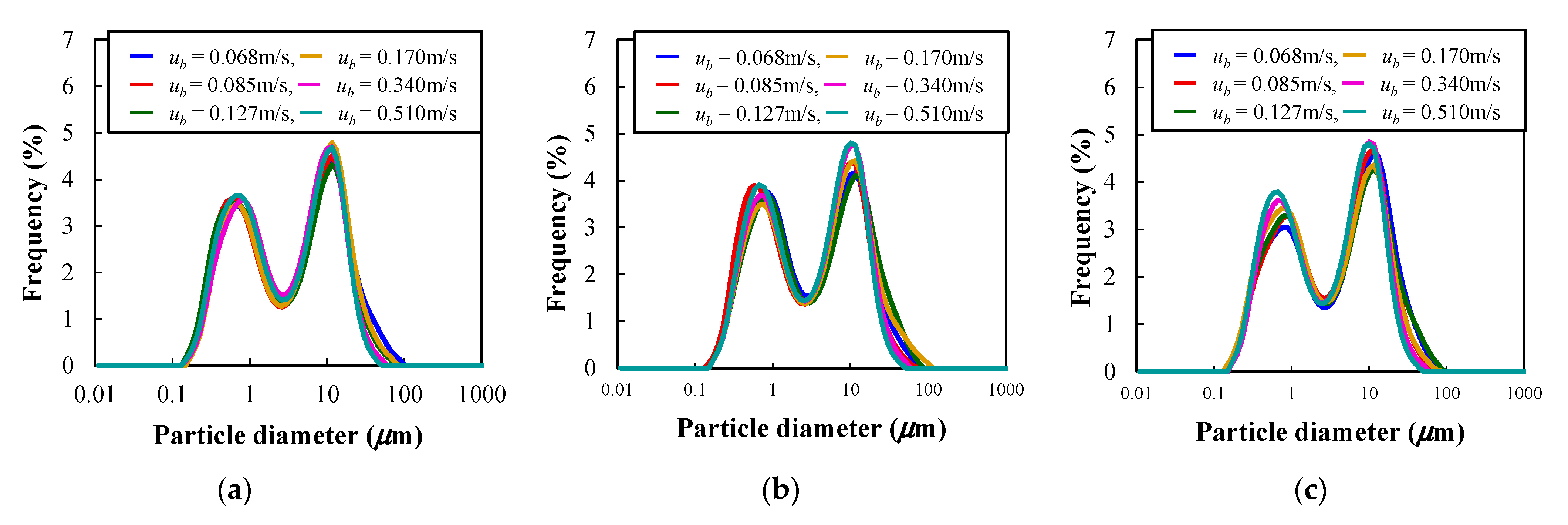
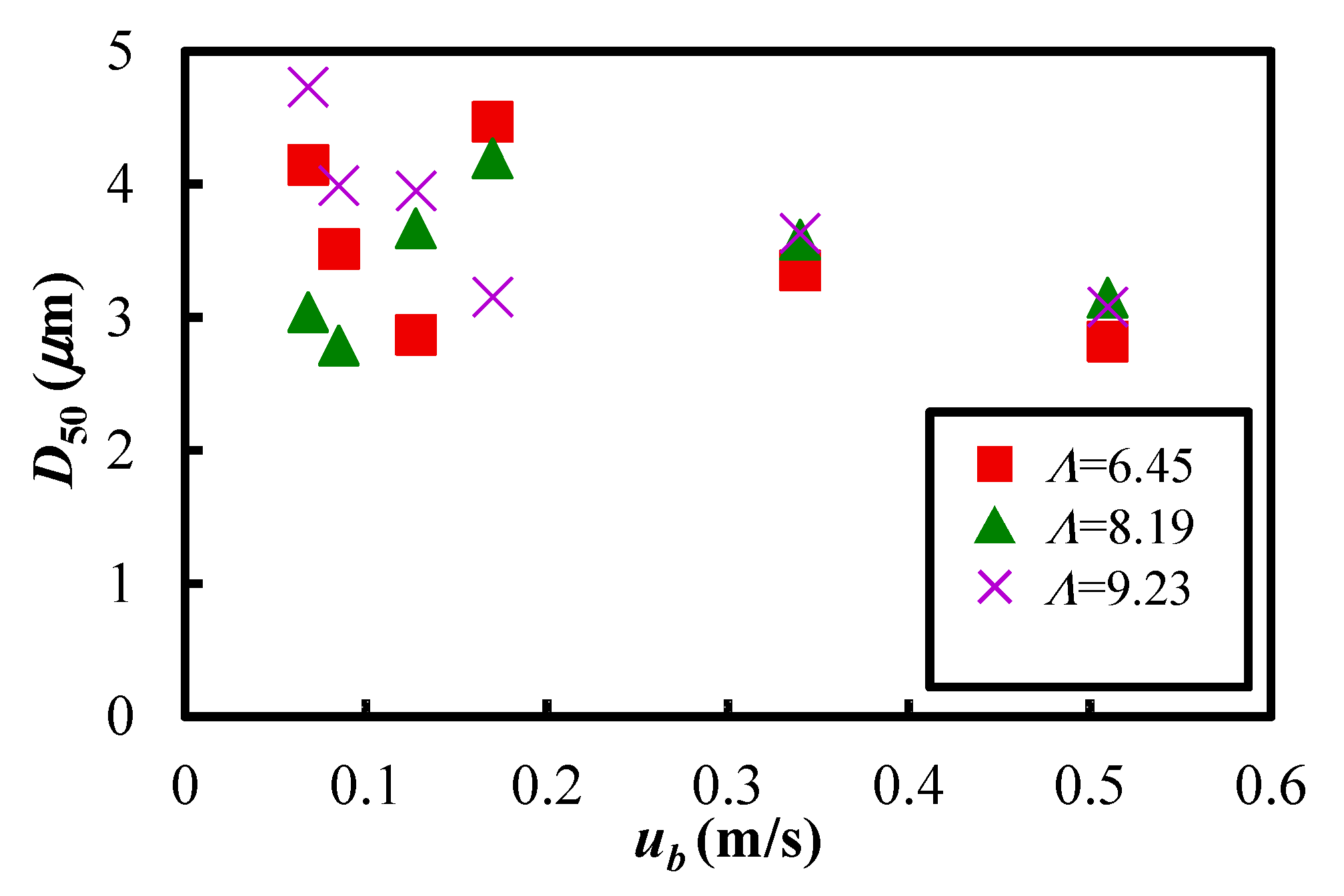
- From the particle size distribution analysis results in the particle dispersion vessel, it was found that the median particle diameter underwent no significant change before and after vibrating fluidization in the experimental conditions of this study. The results show that favourable powder flow could be obtained in the present experimental system.
Author Contributions
Funding
Institutional Review Board Statement
Informed Consent Statement
Data Availability Statement
Acknowledgments
Conflicts of Interest
References
- Kuroda, S.; Watanabe, M.; Kim, K.; Katanoda, H. Current status and future prospects of warm spray technology. J. Therm. Spray Technol. 2011, 20, 653–676. [Google Scholar] [CrossRef] [Green Version]
- Matikainen, V.; Koivuluoto, H.; Vuoristo, P. A study of Cr3C2-based HVOF- and HVAF-sprayed coatings: Abrasion, dry particle erosion and cavitation erosion resistance. Wear 2020, 446–447, 203188. [Google Scholar] [CrossRef]
- Bolelli, G.; Bursi, M.; Lusvarghi, L.; Manfredini, T.; Matikainen, V.; Rigon, R.; Sassatelli, P.; Vuoristo, P. Tribology of FeVCrC coatings deposited by HVOF and HVAF thermal spray process. Wear 2018, 394–395, 113–133. [Google Scholar] [CrossRef]
- Baiamonte, L.; Bjorklund, S.; Mulone, A.; Klement, U.; Joshi, S. Carbide-laden coatings deposited using a hand-held high-velocity air-fuel (HVAF) spray gun. Surf. Coat. Technol. 2021, 406, 126725. [Google Scholar] [CrossRef]
- Govande, A.R.; Chandak, A.; Sunil, B.R.; Dumpala, R. Carbide-based thermal spray coatings: A review on performance characteristics and post-treatment. Int. J. Refract. Met. Hard Mater. 2022, 103, 105772. [Google Scholar] [CrossRef]
- Sakaki, K. The progress state and problem of in new thermal spray technology “Cold Spray”. Surface Technol. 2012, 63, 541–547. (In Japanese) [Google Scholar]
- Stoltenhoff, T.; Borchers, C.; Gartner, F.; Kreye, H. Microstructures and key properties of cold-sprayed and thermally sprayed copper coatings. Surf. Coat. Technol. 2006, 200, 4947–4960. [Google Scholar] [CrossRef]
- Gartner, F.; Stoltenhoff, T.; Voyer, J.; Kreye, H.; Riekehr, S.; Kocak, M. Mechanical properties of cold-spray and thermal sprayed cooper coatings. Surf. Coat. Technol. 2006, 200, 6770–6782. [Google Scholar] [CrossRef]
- Sun, J.; Yamanaka, K.; Zhou, S.; Saito, H.; Ichikawa, Y.; Ogawa, K.; Chiba, A. Adhesion mechanism of cold-sprayed Sn coatings on carbon fiber reinforced plastics. Appl. Surf. Sci. 2022, 579, 151873. [Google Scholar] [CrossRef]
- Poza, P.; Garrido-Maneiro, M.A. Cold-sprayed coatings: Microstructure, mechanical properties, and wear behaviour. Prog. Mater. Sci. 2022, 123, 100839. [Google Scholar] [CrossRef]
- Gwalani, B.; Song, M.; Silverstein, J.; Escobar, J.; Wang, T.; Pole, M.; Johnson, K.; Jasthi, B.K.; Devaraj, A.; Ross, K. Thermal stability and mechanical properties of cold sprayed Nickel-Yttria coating. Scr. Mater. 2022, 207, 114281. [Google Scholar] [CrossRef]
- Akedo, J. Aerosol deposition of ceramic thick films at room temperature: Densification mechanism of ceramic layers. J. Am. Ceram. Soc. 2006, 89, 1834–1839. [Google Scholar] [CrossRef]
- Kim, I.-S.; Ko, P.-J.; Cho, M.-Y.; Lee, Y.-S.; Sohn, H.; Park, C.; Shin, W.H.; Koo, S.-M.; Lee, D.-W.; Oh, J.-M. Fabrication of high-quality alumina coating through novel, dual-particle aerosol deposition. Ceram. Int. 2020, 46, 23686–23694. [Google Scholar] [CrossRef]
- Yu, H.K.; Oh, S.; Choi, K.H.; Jeon, J.; Dong, X.; Lee, S.H.; Choi, J.-Y.; Akedo, J.; Park, J.H. Al2O3 coated glass by aerosol deposition with excellent mechanical properties for mobile electronic displays. Ceram. Int. 2021, 47, 30531–30535. [Google Scholar] [CrossRef]
- Mitani, K.; Mitani, E. HVAF thermal spraying equipment for low-temperature spraying. JP 2017, 2017-8394, 1–10. [Google Scholar]
- Mitani, K.; Mitani, E.; Kawahara, H. Combustion mechanism that enables ignition and flame stability in HVAF spraying equipment. JP 2020, 2020-29583, 1–10. [Google Scholar]
- Kawahara, H.; Furukawa, K.; Ogata, K.; Mitani, E.; Mitani, K. Experimental study on the stabilization mechanism of diffusion flames in a curved impinging spray combustion field in a narrow region. Energies 2021, 14, 7171. [Google Scholar] [CrossRef]
- Viscusi, A.; Ammendola, P.; Astarita, A.; Raganati, F.; Scherillo, F.; Squillance, A.; Chirone, R.; Carrino, L. Aluminum foam made via a new method based on cold gas dynamic sprayed powders mixed through sound assisted fluidization technique. J. Mater. Processing Technol. 2016, 231, 265–276. [Google Scholar] [CrossRef]
- Mawatari, Y.; Tatemoto, Y.; Noda, K. Prediction of minimum fluidization velocity for vibrated fluidized bed. Powder Technol. 2003, 131, 66–70. [Google Scholar] [CrossRef]
- Mawatari, Y.; Tsunekawa, M.; Tatemoto, Y.; Noda, K. Favorable vibrated fluidization conditions for cohesive fine particles. Powder Technol. 2005, 154, 54–60. [Google Scholar] [CrossRef]
- Hakim, L.F.; Portman, J.L.; Casper, M.D.; Weimer, A.W. Aggregation behavior of nanoparticles in fluidized beds. Powder Technol. 2005, 160, 149–160. [Google Scholar] [CrossRef]
- Barletta, D.; Donsi, G.; Ferrari, G.; Poletto, M.; Russo, P. The effect of mechanical vibration on gas fluidization of a fine aeratable powder. Chem. Eng. Res. Des. 2008, 86, 359–369. [Google Scholar] [CrossRef]
- Barletta, D.; Poletto, M. Aggregation phenomena in fluidization of cohesive powders assisted by mechanical vibrations. Powder Technol. 2012, 225, 93–100. [Google Scholar] [CrossRef]
- Cano-Pleite, E.; Shimizu, Y.; Acosta-Iborra, A.; Mawatari, Y. Effect of vertical vibration and particle size on the solids hold-up and mean bubble behavior in a pseudo-2D fluidized bed. Chem. Eng. J. 2016, 304, 384–398. [Google Scholar] [CrossRef]
- Kahrizsangi, H.S.; Sofia, D.; Barletta, D.; Poletto, M. Dust generation in vibrated cohesive powders. Chem. Eng. Trans. 2015, 43, 769–774. [Google Scholar]
- Salehi, H.; Lotrecchiano, N.; Barletta, D.; Poletto, M. Dust release from aggregative cohesive powders subjected to vibration. Ind. Eng. Chem. Res. 2017, 56, 12326–12336. [Google Scholar] [CrossRef]
- Geldart, D. Type of gas fluidization. Powder Technol. 1973, 7, 285–292. [Google Scholar] [CrossRef]
- Carr, R.L. Evaluating flow properties of solids. Chem. Eng. 1965, 72, 163–168. [Google Scholar]
- Carr, R.L. Classifying flow properties of solids. Chem. Eng. 1965, 72, 69–72. [Google Scholar]
- Carr, R.L. Properties of solids. Chem. Eng. 1969, 13, 7–16. [Google Scholar]


| Powder Characteristics | Al2O3 | |
|---|---|---|
| Measured Value | Points | |
| Angle of Repose (deg) | 46 | 14.5 |
| Compressibility (%) | 51.8 | 0 |
| Angle of Spatula (deg) | 66.9 | 12 |
| Cohesiveness (%) | 84.1 | 0 |
| Flowability Index (-) | 26.5 | |
| Flowability | Very Poor | |
| Frequency f (Hz) | Fluidizing Air Velocity ub (m/s) | Secondary Air Velocity ut (m/s) | Vibration Strength Λ (–) |
|---|---|---|---|
| 60 | 0.0017~0.055 | 3.03 | 0~9.23 |
| Frequency f (Hz) | Fluidizing Air Velocity ub (m/s) | Secondary Air Velocity ut (m/s) | Vibration Strength Λ (–) |
|---|---|---|---|
| 60 | 0.068~0.510 | 3.03 | 6.45~9.23 |
| Motor Weight (%) | 54 | 71 | 86 | 100 |
|---|---|---|---|---|
| Amplitude, A (mm) | 0.345 | 0.445 | 0.565 | 0.637 |
| Vibration strength, Λ (–) | 5.0 | 6.45 | 8.19 | 9.23 |
Publisher’s Note: MDPI stays neutral with regard to jurisdictional claims in published maps and institutional affiliations. |
© 2022 by the authors. Licensee MDPI, Basel, Switzerland. This article is an open access article distributed under the terms and conditions of the Creative Commons Attribution (CC BY) license (https://creativecommons.org/licenses/by/4.0/).
Share and Cite
Ogata, K.; Harada, T.; Kawahara, H.; Tokumaru, K.; Abe, R.; Mitani, E.; Mitani, K. Characteristics of Vibrating Fluidization and Transportation for Al2O3 Powder. Materials 2022, 15, 2191. https://doi.org/10.3390/ma15062191
Ogata K, Harada T, Kawahara H, Tokumaru K, Abe R, Mitani E, Mitani K. Characteristics of Vibrating Fluidization and Transportation for Al2O3 Powder. Materials. 2022; 15(6):2191. https://doi.org/10.3390/ma15062191
Chicago/Turabian StyleOgata, Koichiro, Tsutomu Harada, Hideo Kawahara, Kazuki Tokumaru, Riho Abe, Eiji Mitani, and Koji Mitani. 2022. "Characteristics of Vibrating Fluidization and Transportation for Al2O3 Powder" Materials 15, no. 6: 2191. https://doi.org/10.3390/ma15062191
APA StyleOgata, K., Harada, T., Kawahara, H., Tokumaru, K., Abe, R., Mitani, E., & Mitani, K. (2022). Characteristics of Vibrating Fluidization and Transportation for Al2O3 Powder. Materials, 15(6), 2191. https://doi.org/10.3390/ma15062191