
Dynamic Alloying of Steels in the Super-Deep Penetration Mode

 , and
, and 
Abstract
1. Introduction
1.1. Dynamic Alloying in the SDP Mode
1.2. SDP Models
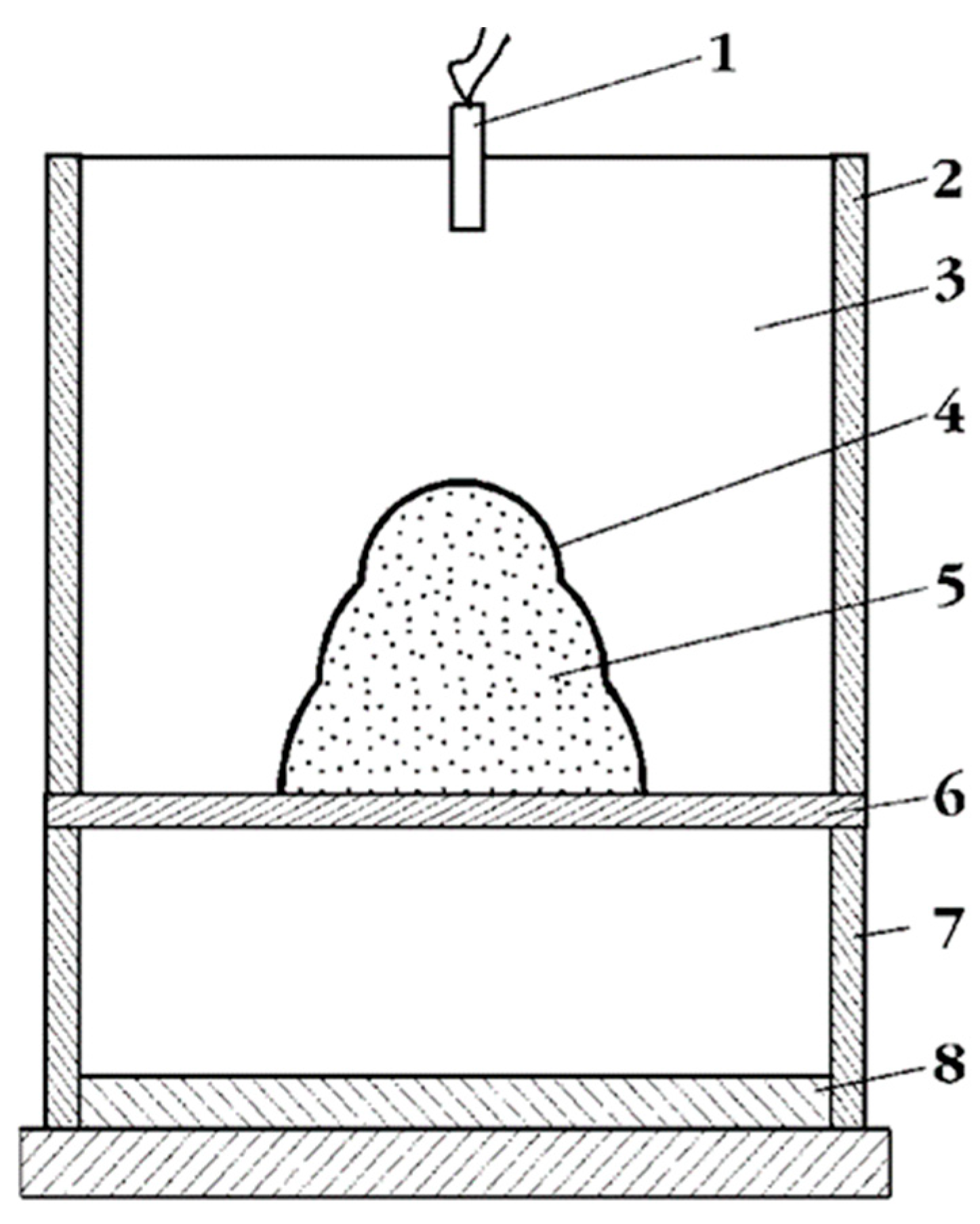
1.3. Powder Particles Acceleration Methods
2. Materials and Methods
2.1. Scanning Electron Microscopy
2.2. Hardness Measurement
2.3. The Mechanical Properties Measurements
3. Results
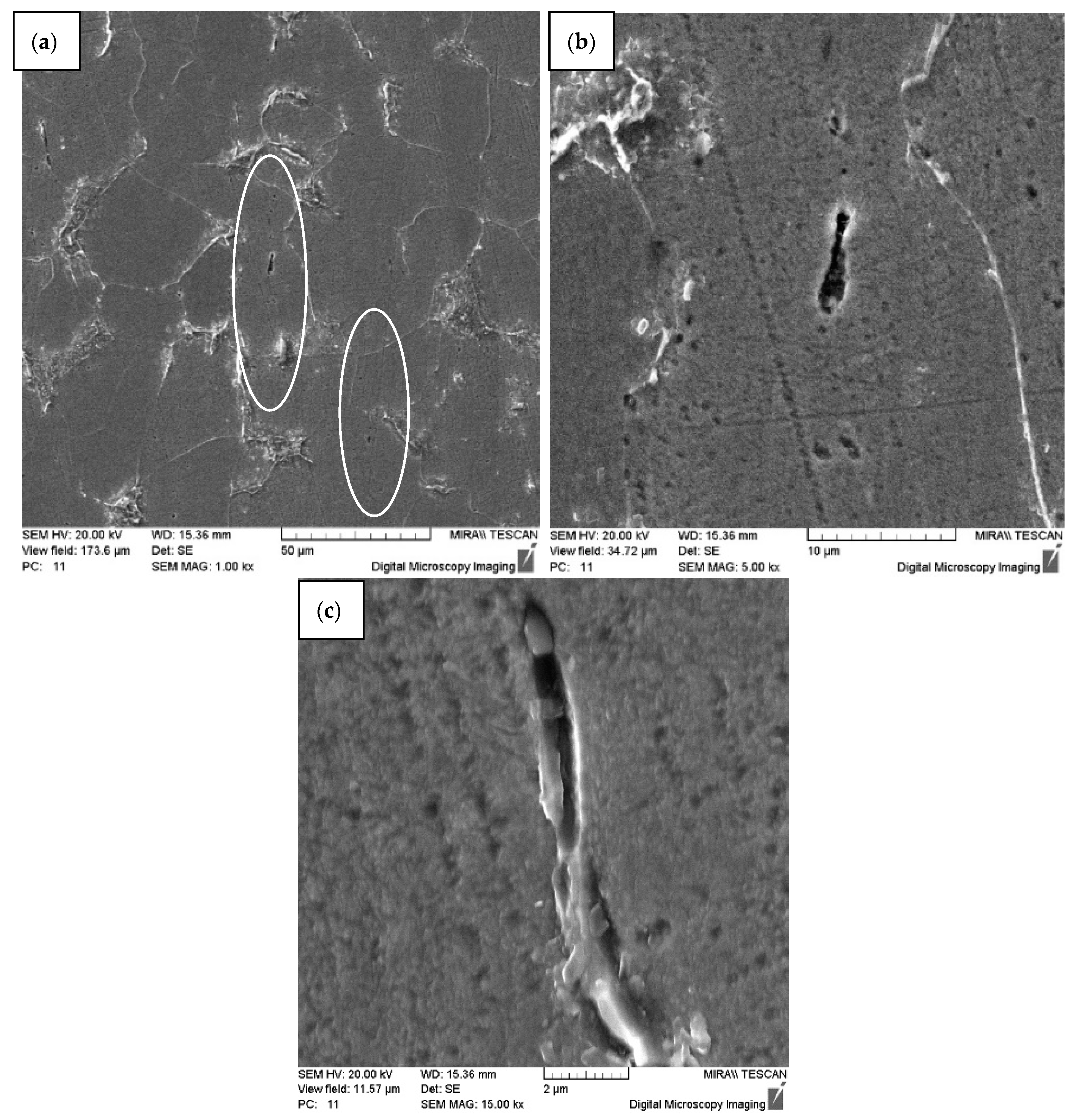
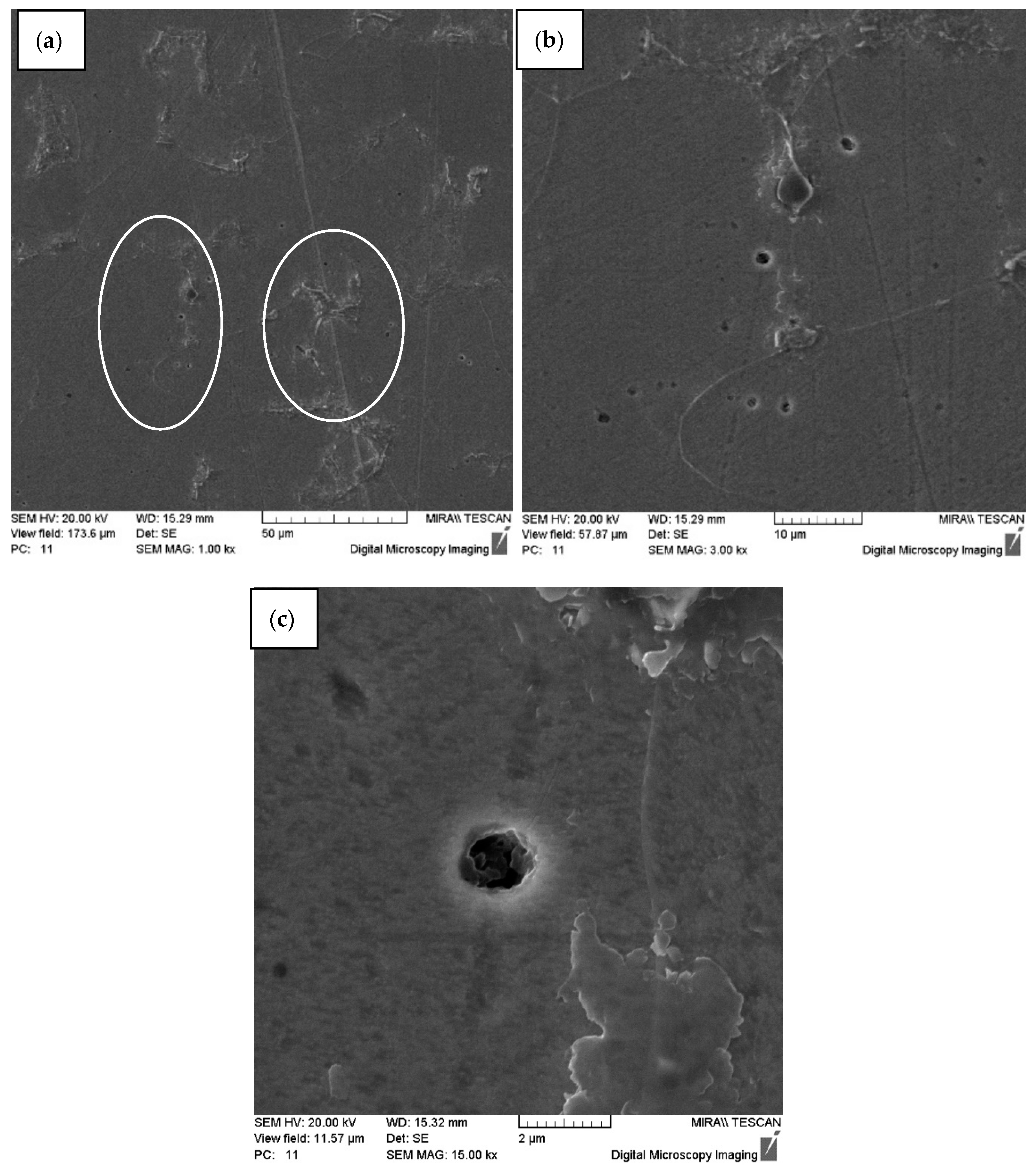
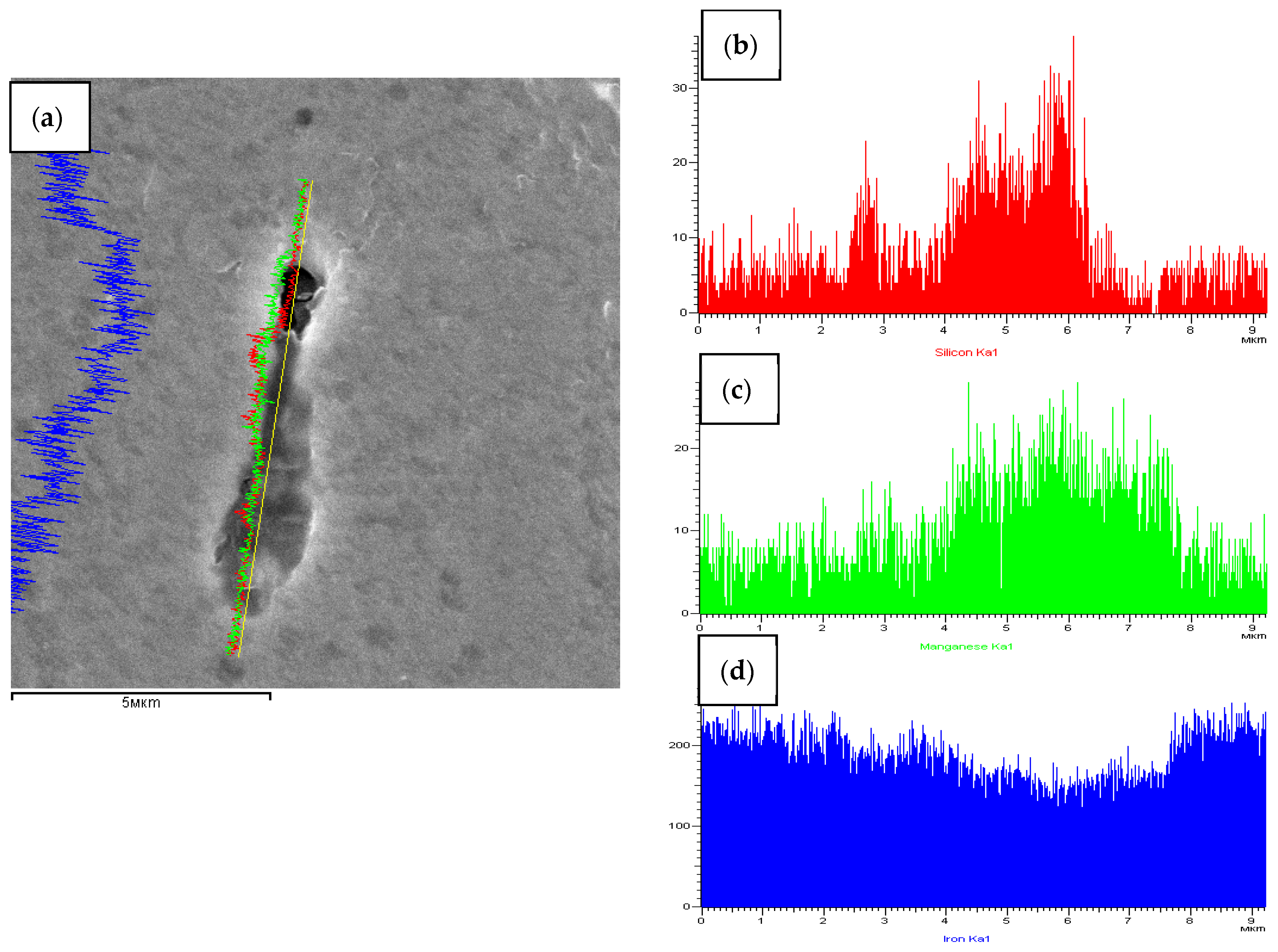
3.1. Changes in the Structure of Carbon Steels after Dynamic Alloying in the SDP Penetration Mode
3.2. Dynamic Alloying of High-Speed Steel W6Mo5Cr4V2 in the SDP Mode
4. Discussion
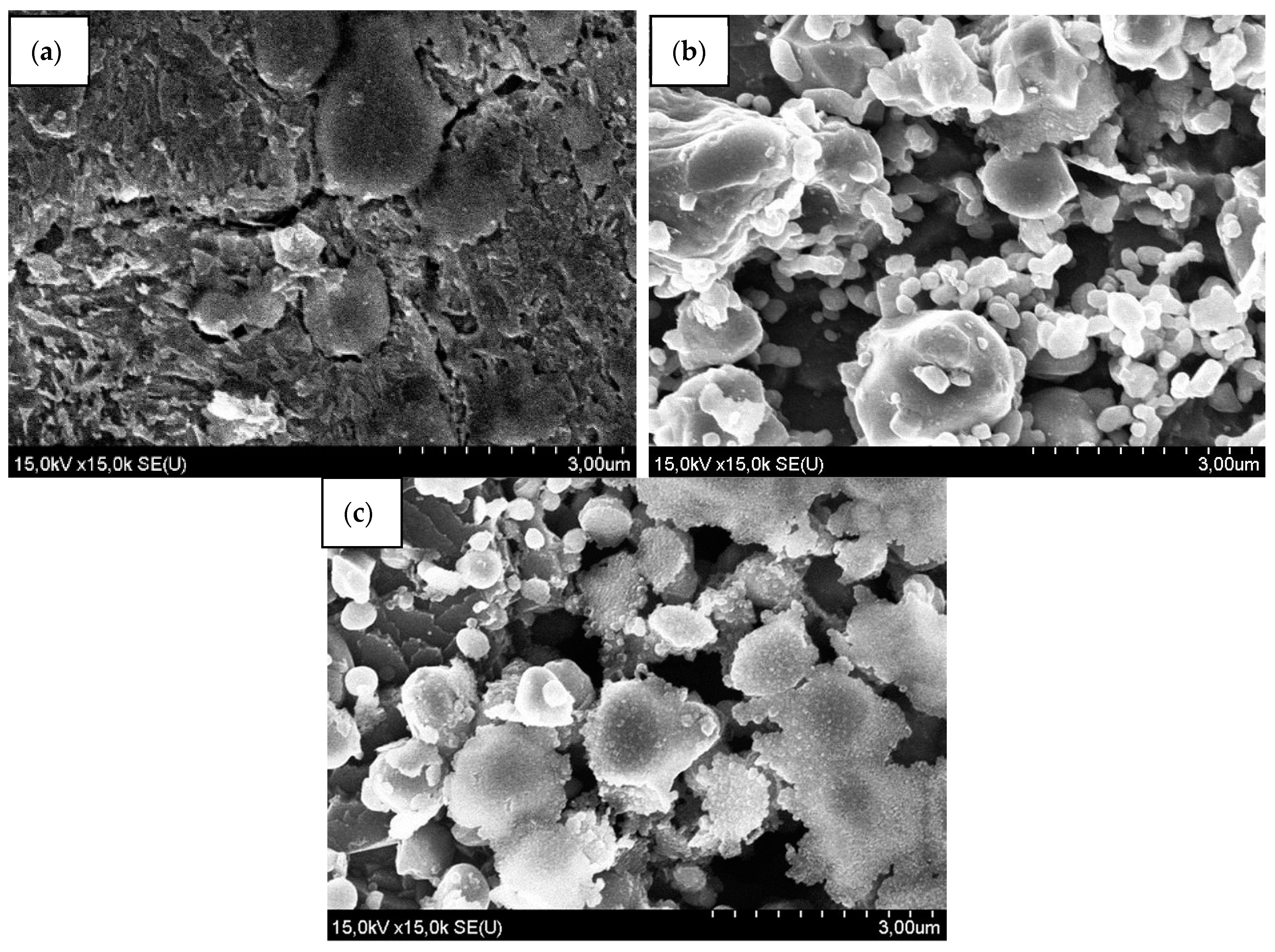
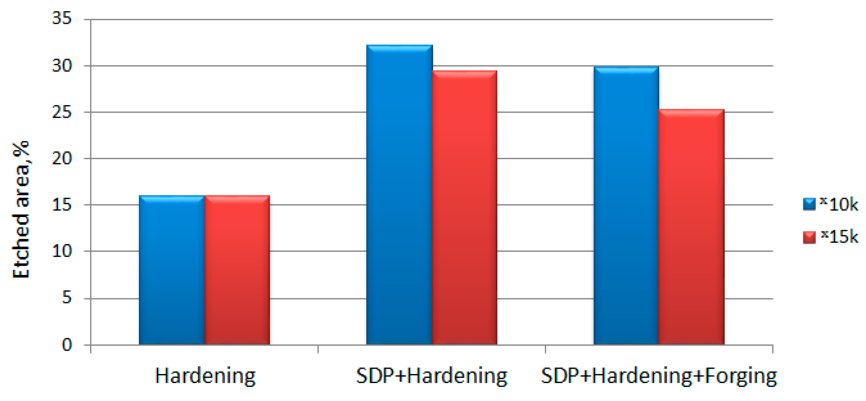
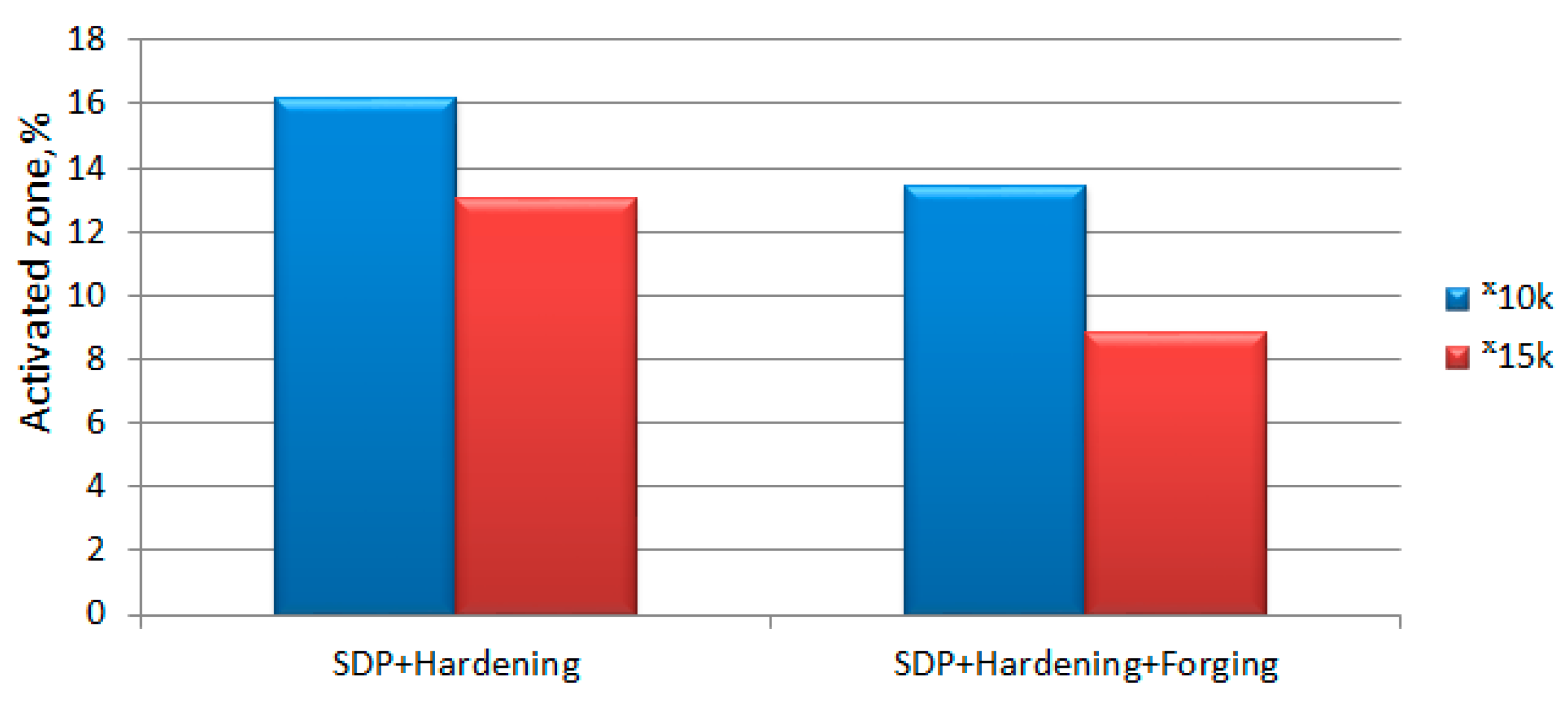
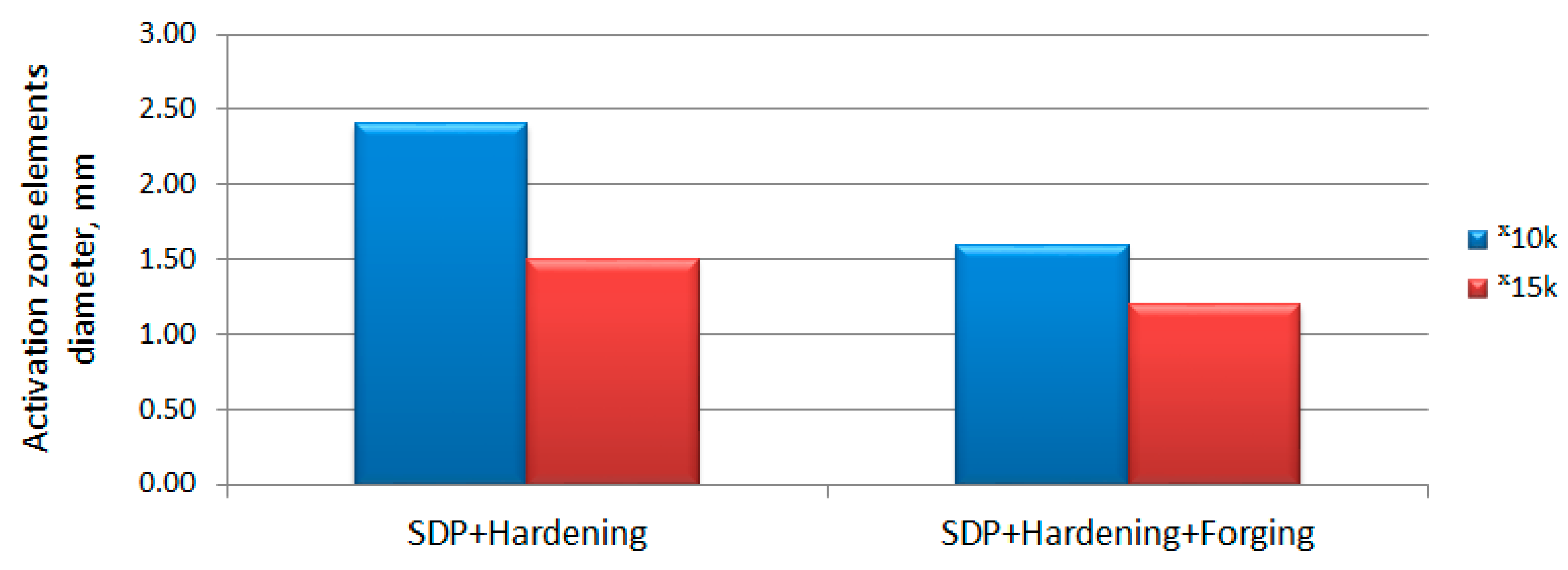
4.1. Changes in the Structure of W6Mo5Cr4V2 Steel at Different Processing Variants
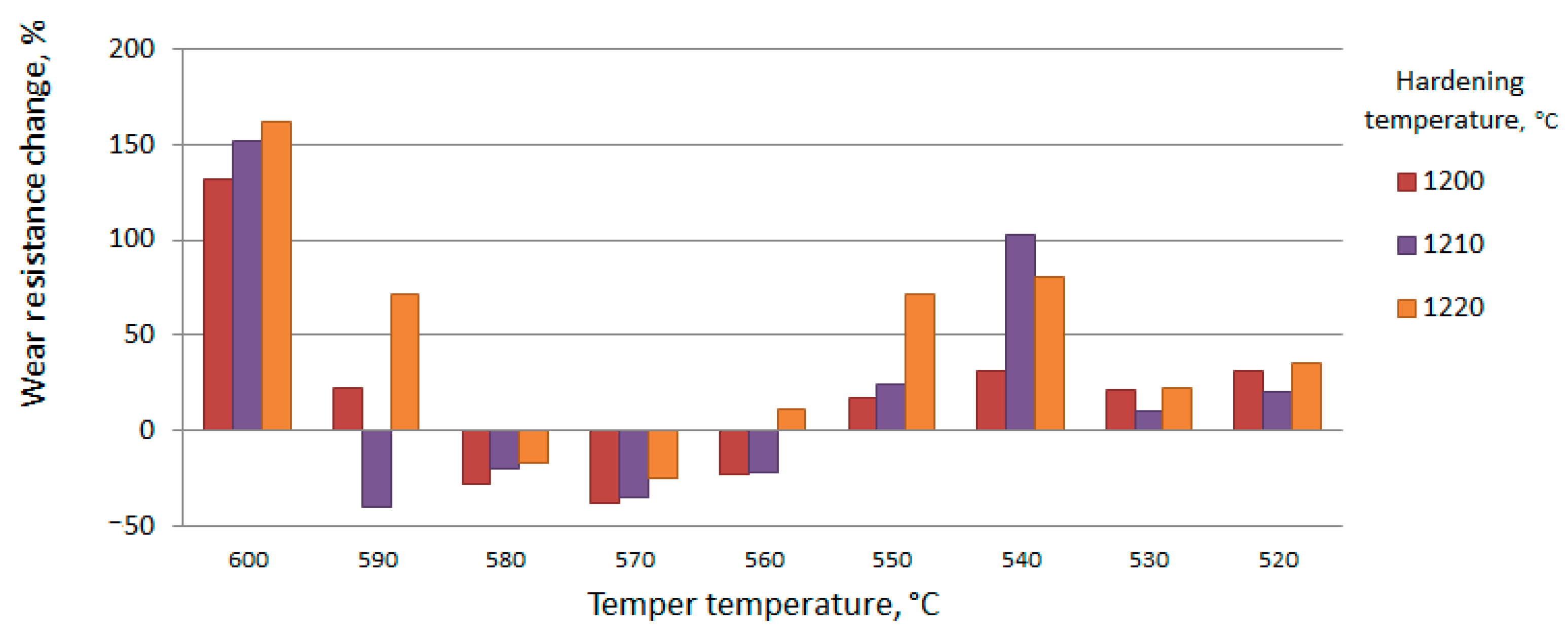
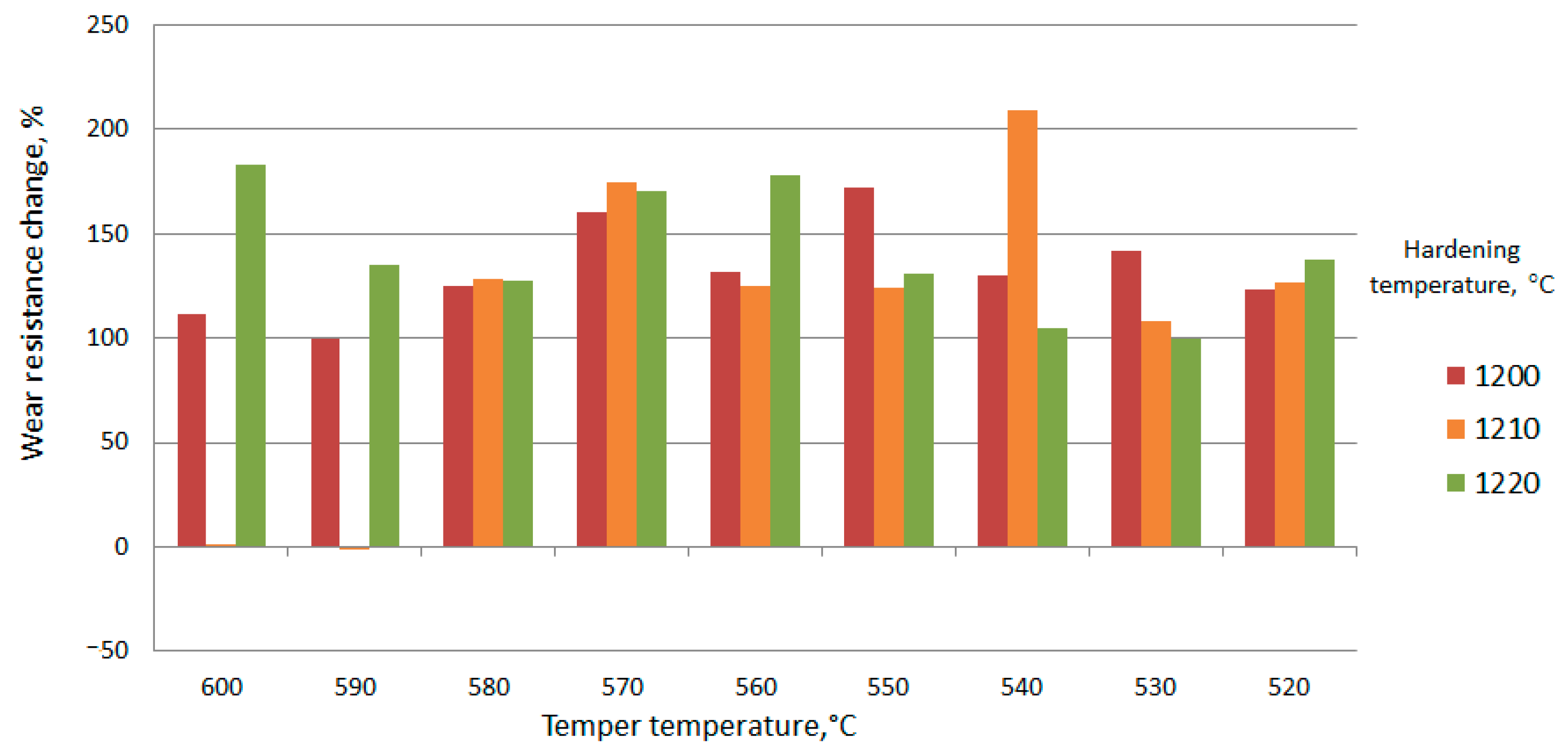
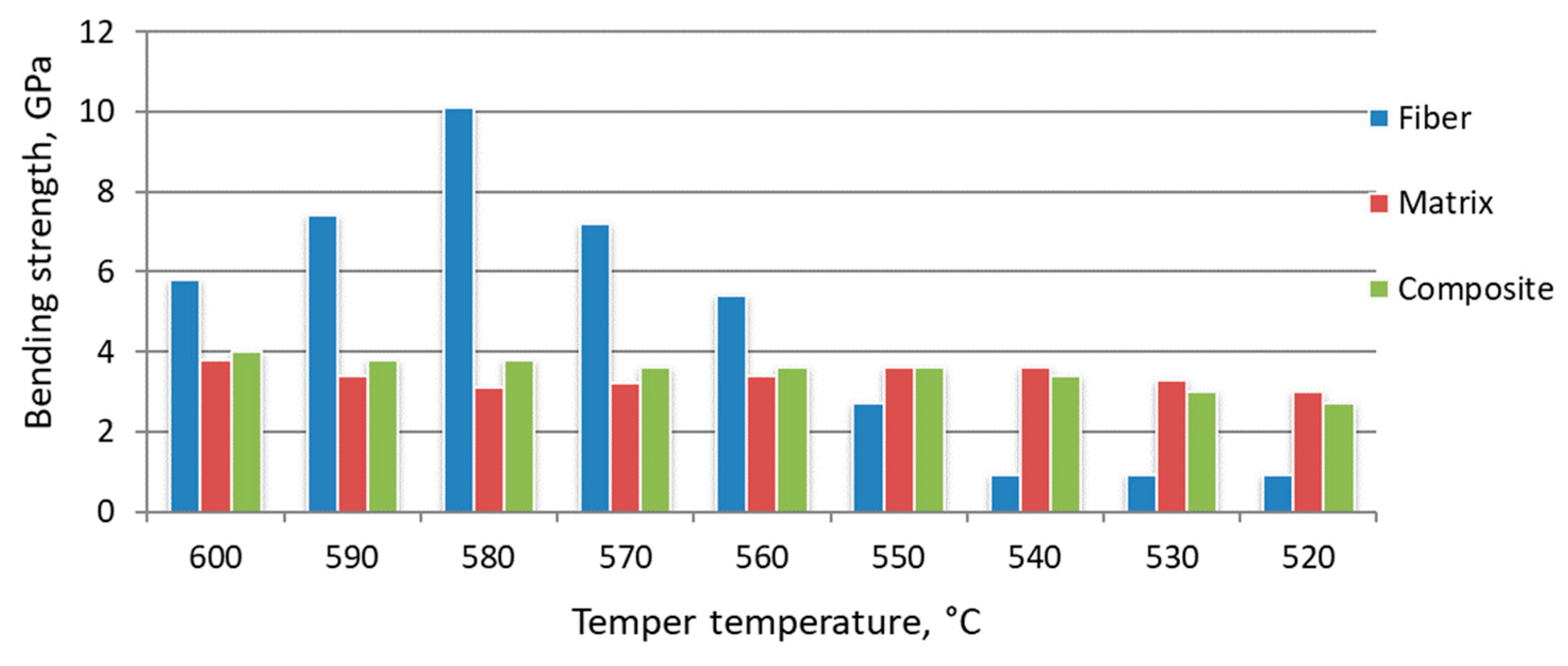
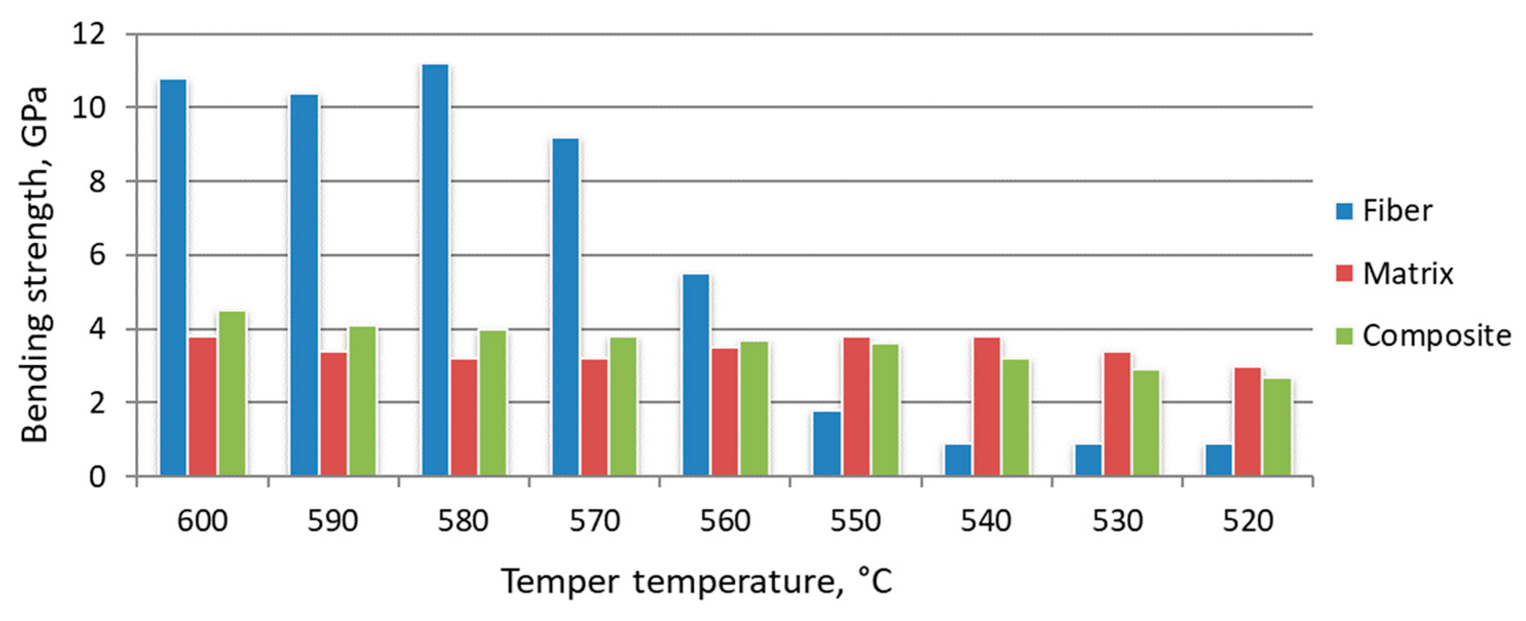
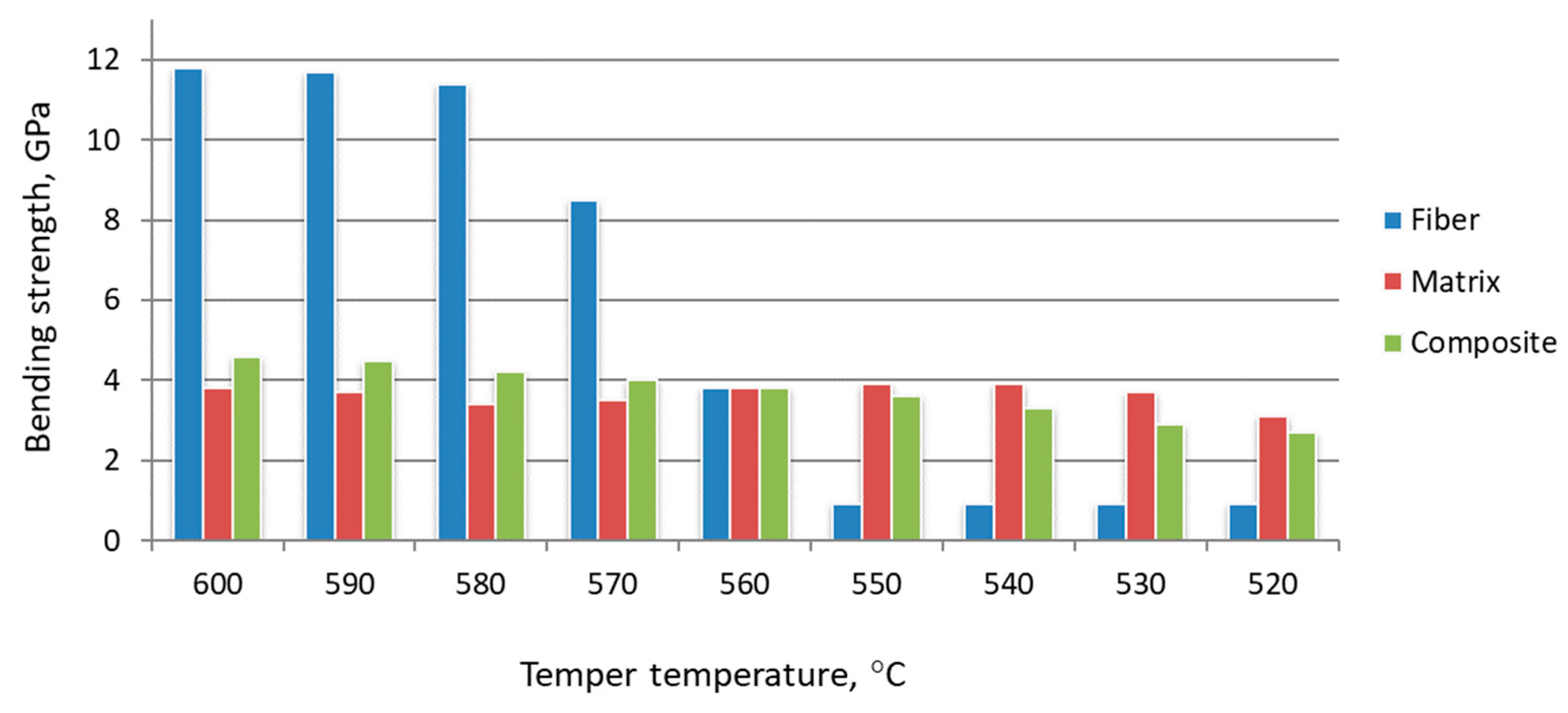
4.2. Changes in Mechanical Properties of W6Mo5Cr4V2 High-Speed Tool Steel, Activated in the SDP Mode by Controlling the Modes of Subsequent Heat Treatment
5. Conclusions
Author Contributions
Funding
Institutional Review Board Statement
Informed Consent Statement
Data Availability Statement
Conflicts of Interest
References
- Europeia, C. Communication from the Commission to the European Parliament, the Council, the European Economic and Social Committee and the Committee of the Regions Critical Raw Materials Resilience: Charting a Path towards Greater Security and Sustainability; European Commission: Brussels, Belgium, 2020. [Google Scholar]
- Shemi, A.; Magumise, A.; Ndlovu, S.; Sacks, N. Recycling of Tungsten Carbide Scrap Metal: A Review of Recycling Methods and Future Prospects. Miner. Eng. 2018, 122, 195–205. [Google Scholar] [CrossRef]
- Rizzo, A.; Goel, S.; Luisa Grilli, M.; Iglesias, R.; Jaworska, L.; Lapkovskis, V.; Novak, P.; Postolnyi, B.O.; Valerini, D. The Critical Raw Materials in Cutting Tools for Machining Applications: A Review. Materials 2020, 13, 1377. [Google Scholar] [CrossRef] [PubMed]
- Fortov, V.E.; Il’kaev, R.I.; Rykovanov, G.N.; Selemir, V.D.; Sharkov, B.Y. Explosions, Powerful Shock Waves, and Extreme States of Matter. Her. Russ. Acad. Sci. 2021, 91, 239–249. [Google Scholar] [CrossRef]
- Kanel’, G.I.; Zaretsky, E.B.; Razorenov, S.V.; Ashitkov, S.I.; Fortov, V.E. Unusual Plasticity and Strength of Metals at Ultra-Short Load Durations. Phys.-Uspekhi 2017, 60, 490–508. [Google Scholar] [CrossRef]
- Korshunov, L.G.; Zeldovich, V.I.; Usherenko, S.; Kheifets, A.E.; Khomskaya, I.V.; Chernenko, N.L.; Frolova, N.Y. Superdeep Penetration of the Microparticles Accelerated by Explosion in Metals and Alloys of Iron. Adv. Mater. Res. 2008, 47–50, 423–426. [Google Scholar] [CrossRef]
- Usherenko, Y.; Usherenko, S.; Yazdani, J. Composite Materials for Steel Cutting and Concrete Crushing. Procedia Eng. 2017, 172, 1198–1203. [Google Scholar] [CrossRef]
- Usherenko, Y.; Usherenko, S.; Yazdani, J. High-Energy Method of Transformation of Casting Metals and Alloys to the Composite Materials. Key Eng. Mater. 2017, 721, 290–294. [Google Scholar] [CrossRef]
- Aleksentseva, S.E.; Krivchenko, A.L. Analysis of Characteristics of Metals and Alloys Processing with the High-Speed Stream of Discrete Particles Dispersed by Explosion Energy of the Channel Charges and Other Dynamic Methods. Vestn. Samara State Tech. Univ. Tech. Sci. Ser. 2013, 21, 71–78. (In Russian) [Google Scholar]
- Fedorov, S.V.; Ladov, S.V.; Nikol’skaya, Y.M. Numerical Analysis of Explosive Formation of High-Velocity Metal Particles from Hemisphere-Cylinder Combined Shaped-Charge Liners for the Objects Testing on Anti-Meteoric Resistance. AIP Conf. Proc. 2021, 2318, 150016. [Google Scholar] [CrossRef]
- Selivanov, V.V.; Fedorov, S.V.; Nikolskaya, Y.M.; Ladov, S.V. Compact Element Formation for the Modeling of the High-Velocity Impacts of Particles onto Spacecraft Materials and Construction Elements in Earth Conditions. Acta Astronaut. 2017, 135, 34–43. [Google Scholar] [CrossRef]
- Chirskaya, N.P.; Ermolaev, I.K.; Novikov, L.S. Interaction of High-Speed Particles with a Solid Barrier. Mosc. Univ. Phys. Bull. 2018, 2, 1820208. (In Russian) [Google Scholar]
- Belous, A.; Saladukha, V.; Shvedau, S. High Velocity Microparticles in Space: Influence Mechanisms and Mitigating Effects of Electromagnetic Irradiation, 1st ed.; Springer International Publishing: Cham, Switzerland, 2019; ISBN 978-3-030-04158-8. [Google Scholar]
- Nuttall, A.; Close, S. A Thermodynamic Analysis of Hypervelocity Impacts on Metals. Int. J. Impact Eng. 2020, 144, 103645. [Google Scholar] [CrossRef]
- Hew, Y.M.; Goel, A.; Close, S.; Lee, N. Hypervelocity Impact Flash and Plasma on Electrically Biased Spacecraft Surfaces. Int. J. Impact Eng. 2018, 121, 1–11. [Google Scholar] [CrossRef]
- Soulard, L.; Durand, O.; Prat, R.; Carrard, T. High Velocity Impact of a Spherical Particle on a Surface: Theory and Simulation of the Jet Formation. J. Appl. Phys. 2021, 129, 205104. [Google Scholar] [CrossRef]
- Semkin, N.D.; Sukhachev, K.I.; Dorofeev, A.S. Methods and means of accelerating particles of natural and technogenic origin (In Russian). Vestn. Samara Univ. Aerosp. Mech. Eng. 2015, 14, 171–191. [Google Scholar] [CrossRef][Green Version]
- Veysset, D.; Lee, J.-H.; Hassani, M.; Kooi, S.E.; Thomas, E.L.; Nelson, K.A. High-Velocity Micro-Projectile Impact Testing. Appl. Phys. Rev. 2021, 8, 011319. [Google Scholar] [CrossRef]
- Veysset, D.; Sun, Y.; Kooi, S.E.; Lem, J.; Nelson, K.A. Laser-Driven High-Velocity Microparticle Launcher in Atmosphere and under Vacuum. Int. J. Impact Eng. 2020, 137, 103465. [Google Scholar] [CrossRef]
- Qi, C.; Chen, J. Physical Mechanism of Super-Deep Penetration of Solid Microparticles into Solid Targets. J. Mech. Behav. Mater. 2014, 23, 21–26. [Google Scholar] [CrossRef]
- Krestelev, A.I. Simulation of the process of entrainment of a powder particles by explosive shock waves. J. Samara State Tech. Univ. SER Phys. Math. Sci. 2014, 2, 125–129. (In Russian) [Google Scholar] [CrossRef][Green Version]
- Baskevych, O.S.; Sobolev, V.V.; Sereda, B.P. Modeling the influence of shock waves on the stability of chemical links during super-deep penetration of microparticles. Math. Model. 2020, 1, 116–124. [Google Scholar] [CrossRef]
- Trofimov, V.S.; Petrov, E.V.; Alymov, M.I. On the Nature of Superdeep Penetration of Shock-Accelerated Particles into a Solid Target. Int. J. Self-Propagating High-Temp. Synth. 2016, 25, 125–128. [Google Scholar] [CrossRef]
- Yildirim, B.; Yang, H.; Gouldstone, A.; Müftü, S. Rebound Mechanics of Micrometre-Scale, Spherical Particles in High-Velocity Impacts. Proc. R. Soc. Math. Phys. Eng. Sci. 2017, 473, 20160936. [Google Scholar] [CrossRef] [PubMed]
- Schill, W.; Wasem, J.V.; Owen, J.M. Modelling and Simulation of Cratering and Ejecta Production during High Velocity Impacts. J. Dyn. Behav. Mater. 2017, 3, 180–188. [Google Scholar] [CrossRef]
- Rojas, D.F.; Orhan, O.K.; Ponga, M. Dynamic Recrystallization of Silver Nanocubes during High-Velocity Impacts. Acta Mater. 2021, 212, 116892. [Google Scholar] [CrossRef]
- Sakong, J.; Woo, S.-C.; Kim, J.-Y.; Kim, T.-W. Study on Material Fracture and Debris Dispersion Behavior via High Velocity Impact. Trans. Korean Soc. Mech. Eng. A 2017, 41, 1065–1075. [Google Scholar] [CrossRef]
- Al-Lafi, W.; Jin, J.; Song, M. Mechanical Response of Polycarbonate Nanocomposites to High Velocity Impact. Eur. Polym. J. 2016, 85, 354–362. [Google Scholar] [CrossRef]
- Zhu, Y.; Wang, H.; Gao, Z.; Cai, W. Martensitic Transformation and Microstructure of Dual-Phase Ti44Ni47Nb9 Shape Memory Alloy after High-Velocity Impact. Mater. Charact. 2016, 122, 162–169. [Google Scholar] [CrossRef]
- Liu, J.; Long, Y.; Ji, C.; Zhong, M.; Liu, Q. The Influence of Liner Material on the Dynamic Response of the Finite Steel Target Subjected to High Velocity Impact by Explosively Formed Projectile. Int. J. Impact Eng. 2017, 109, 264–275. [Google Scholar] [CrossRef]
- Savinykh, A.S.; Kanel, G.I.; Garkushin, G.V.; Razorenov, S.V. Resistance to High-Rate Deformation and Fracture of Lead at Normal and Elevated Temperatures in the Sub-Microsecond Time Range. J. Appl. Phys. 2020, 128, 025902. [Google Scholar] [CrossRef]
- Kanel, G.I.; Savinykh, A.S.; Garkushin, G.V.; Razorenov, S.V. Effects of Temperature and Strain on the Resistance to High-Rate Deformation of Copper in Shock Waves. J. Appl. Phys. 2020, 128, 115901. [Google Scholar] [CrossRef]
- Suresh, S.; Lee, S.-W.; Aindow, M.; Brody, H.D.; Champagne, V.K.; Dongare, A.M. Unraveling the Mesoscale Evolution of Microstructure during Supersonic Impact of Aluminum Powder Particles. Sci. Rep. 2018, 8, 10075. [Google Scholar] [CrossRef]
- Tanaka, S.; Mori, A.; Oda, H.; Inao, D.; Hokamoto, K. Surface Coating by Tungsten Carbide Particles on a Metal Substrate by High Velocity Collision. Sci. Technol. Energ. Mater. 2017, 78, 93–98. [Google Scholar]
- Petrov, E.V.; Trofimov, V.S.; Kopytskiy, V.O. Study of the High-Velocity Impact of Tungsten Particles with a Steel Target. J. Phys. Conf. Ser. 2020, 1431, 012044. [Google Scholar] [CrossRef]
- Atroshenko, S.A.; Grigor’ev, A.Y.; Savenkov, G.G. Mechanisms of Plastic Deformation in Stainless Steel under Conditions of High-Speed Penetration of Compact Strikers. Phys. Solid State 2019, 61, 1690–1694. [Google Scholar] [CrossRef]
- Aleksentseva, S.E.; Zaharov, I.V. Explosive microalloying and hardening by a flow of high-velocity particles of welded seams of rail joints and structures. Russ. Metall. Met. 2018, 18–24. (In Russian) [Google Scholar] [CrossRef]
- Chernikov, D.G.; Yusupov, P.Y.; Glushchenkov, V.A.; Karpukhin, V.F.; Belyaeva, I.A.; Prokofiev, A.B. Magnetic Pulse Processing of Materials (MIOM); SSM: Samara, Russia, 2019; ISBN 978-5-604-35934-1. (In Russian) [Google Scholar]
- Usherenko, Y.; Mironovs, V.; Lapkovskis, V.; Usherenko, S.; Gluschenkov, V. Powder Particle Flow Acceleration Methods for Simulation of Interaction with Materials Used in Spacecrafts. Agron. Res. 2019, 17, 2445–2454. [Google Scholar] [CrossRef]
- Fortov, V.E. Extreme States of Matter on Earth and in Space. Phys.-Uspekhi 2009, 52, 615–647. [Google Scholar] [CrossRef]
- Petrov, E.V.; Saikov, I.V.; Saikova, G.R.; Trofimov, V.S. Properties of the Surface Layer after High-Energy Treatment by Powder Particles. Russ. J. Non-Ferr. Met. 2020, 61, 549–553. [Google Scholar] [CrossRef]
- Usherenko, Y.; Mironov, V.; Usherenko, S. Analysis of the Effects of Dynamic Alloying on the Structure of Aluminium and Its Alloys. Solid State Phenom. 2021, 320, 8–13. [Google Scholar] [CrossRef]
- Usherenko, Y.; Mironovs, V.; Usherenko, S.; Reut, O.; Lapkovskis, V. Properties of Technical Aluminum under the Effect of Dynamic Alloying. IOP Conf. Ser. Mater. Sci. Eng. 2021, 1140, 012037. [Google Scholar] [CrossRef]
- Khudnev, A.A.; Plokhikh, A.I.; Dvoretskov, R.M.; Schetanov, B.V. Investigation of Diffusion of Alloying Elements during Thermal Cycling of Multilayer Composite Material Made of Chrome and Carbon Steels. Proc. VIAM 2021, 4, 74–91. [Google Scholar] [CrossRef]


| Formula | Phase Name | Content (%) |
|---|---|---|
| SiC | Moissanite-6H | 86 |
| C | graphite | 6 |
| C60 | fullerite | 8 |
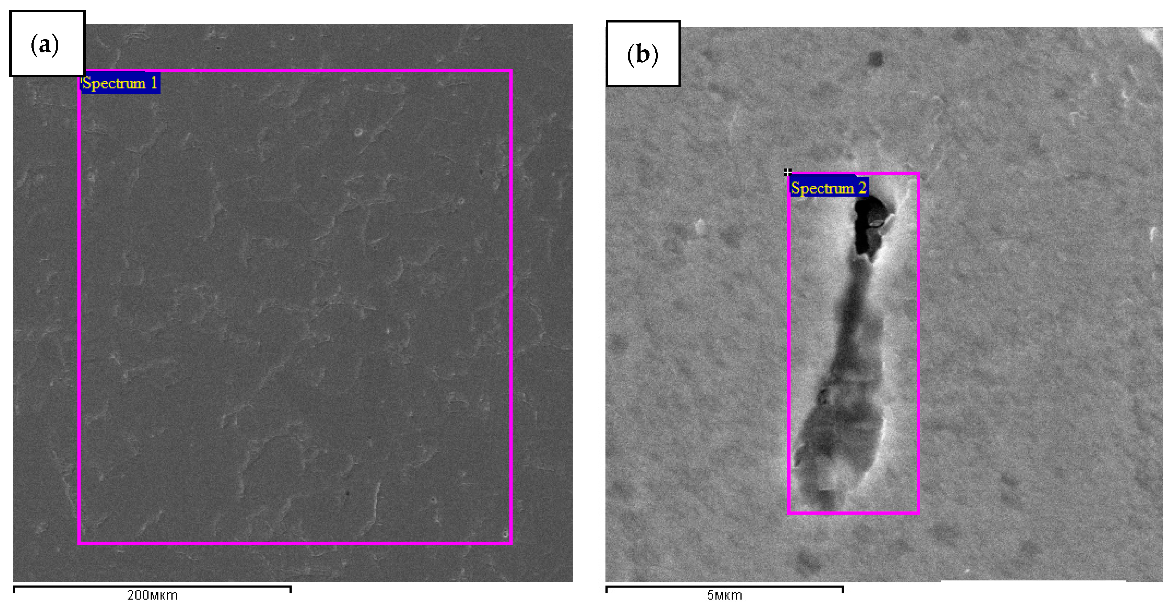
| Spectrum | Elemental Concentration, % | ||||
|---|---|---|---|---|---|
| Si | S | Mn | Fe | Sum | |
| 1 | 0.3 | 0.1 | 0.7 | 98.9 | 100.0 |
| 2 | 1.2 | 0.1 | 1.2 | 97.6 | 100.0 |
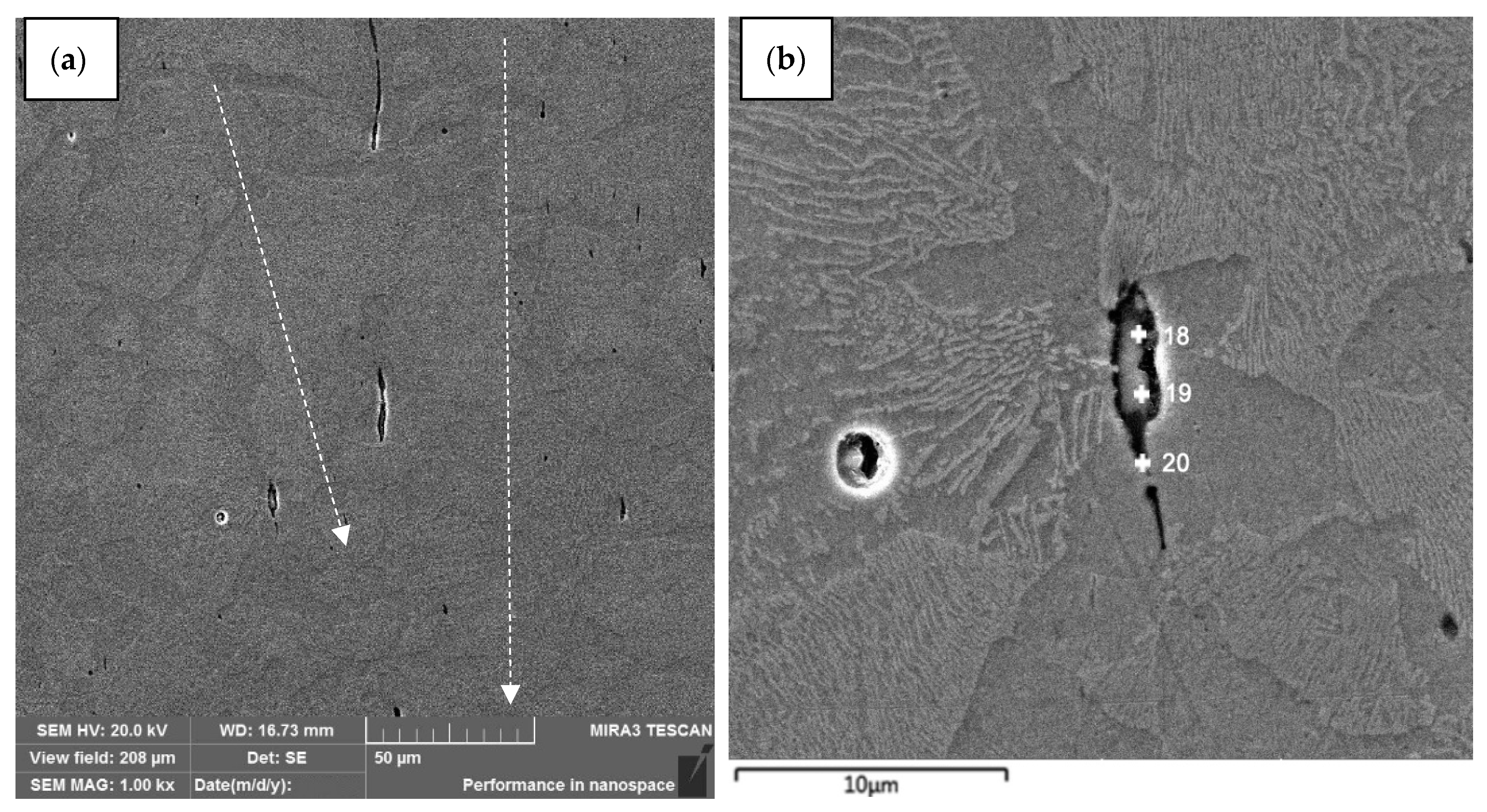
| Point | Elemental Concentration, % | ||||
|---|---|---|---|---|---|
| Si | S | Mn | Fe | Sum | |
| 18 | 1.12 | 20.02 | 37.67 | 41.19 | 100.0 |
| 19 | 1.20 | 25.46 | 52.75 | 20.59 | 100.0 |
| 20 | 1.32 | 0.00 | 3.35 | 95.33 | 100.0 |
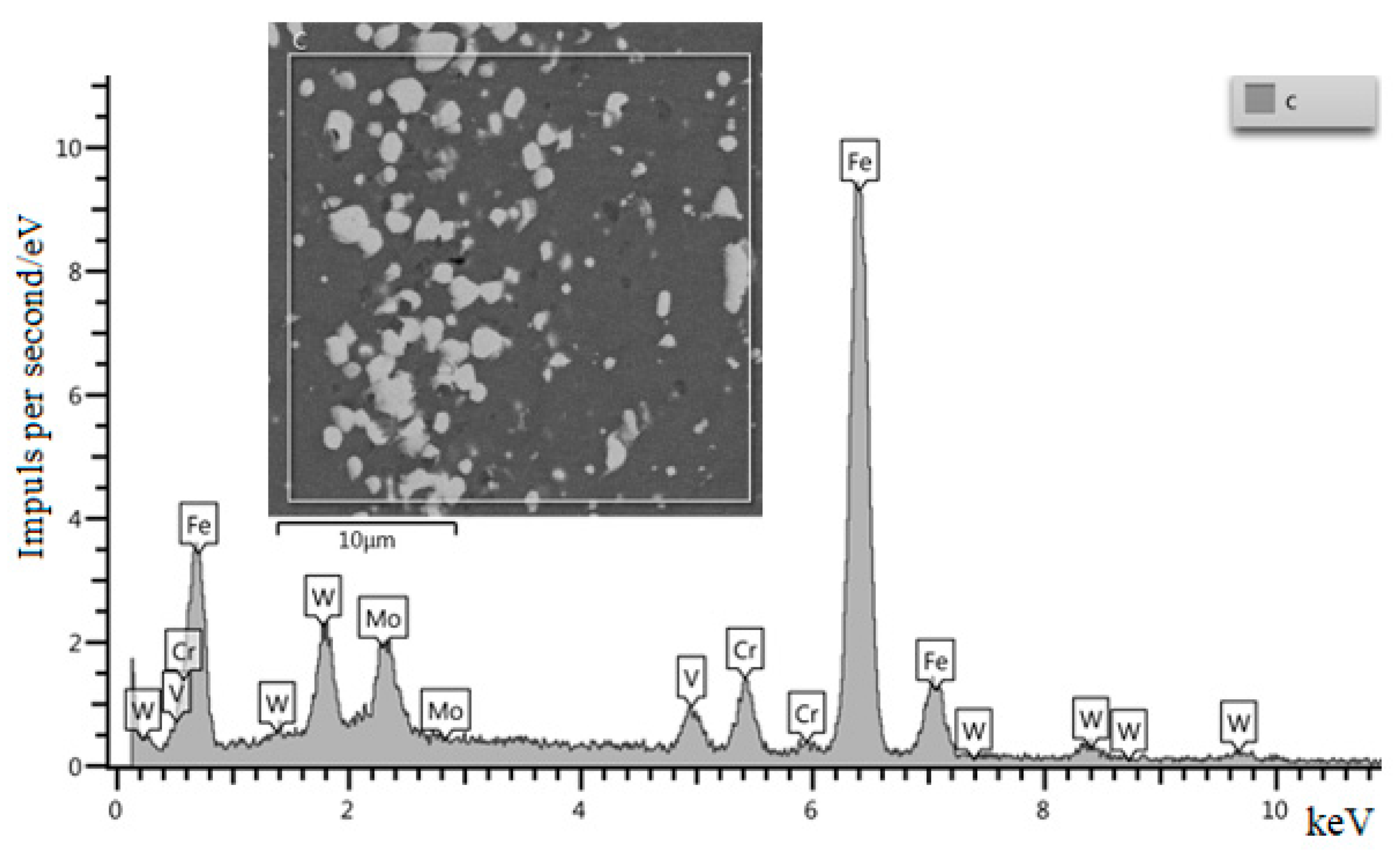
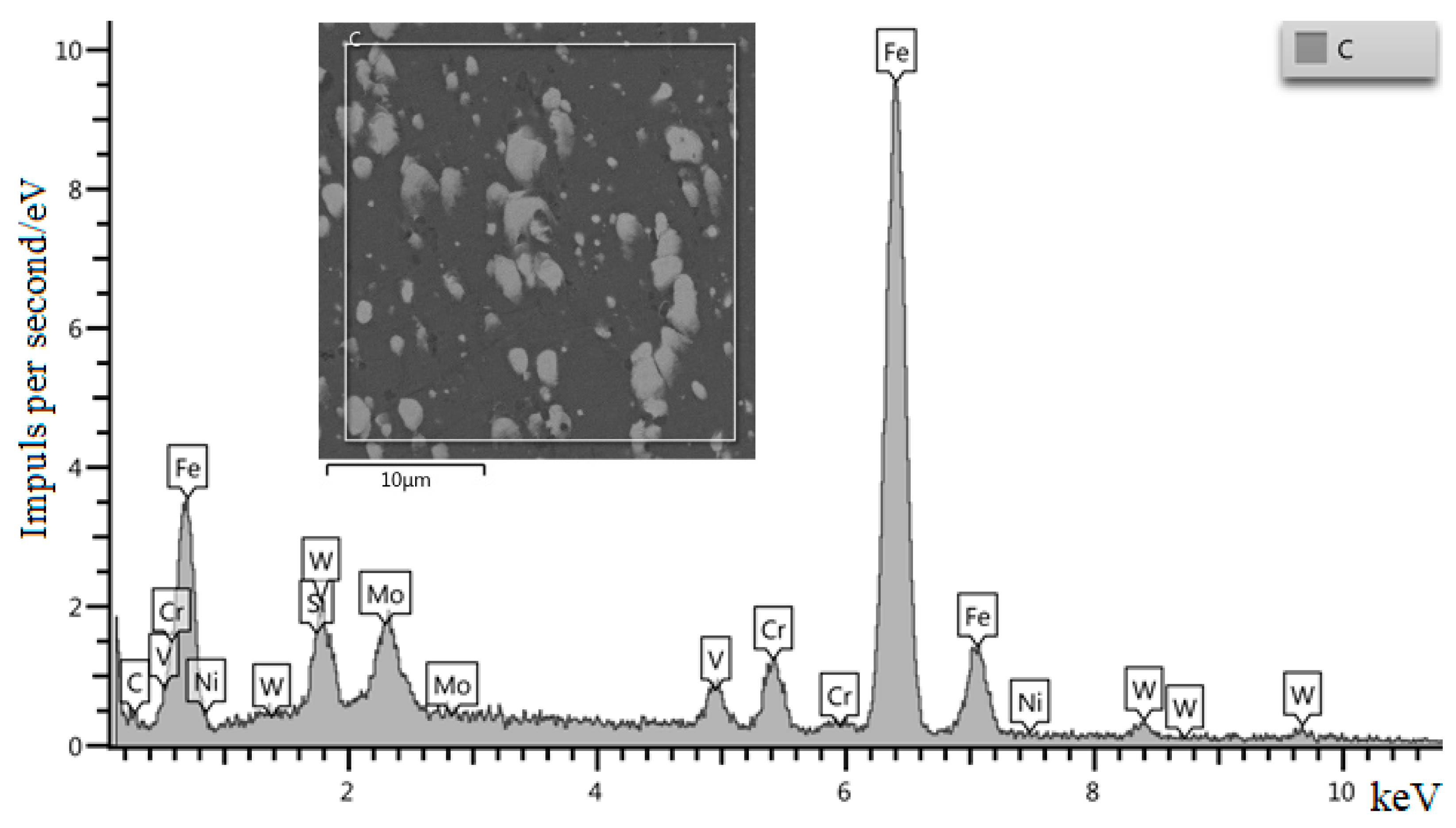
| Point | Elemental Concentration, % | |||||||
|---|---|---|---|---|---|---|---|---|
| Si | V | Cr | Fe | Ni | Mo | W | Sum | |
| 1 | 0.5 | 0.8 | 6.3 | 89.5 | 0.5 | 1.3 | 1.1 | 100.0 |
| Sample | HBW Average before Hardening | HRC Average before Hardening | HBW Average after Hardening | HRC Average after Hardening |
|---|---|---|---|---|
| Initial | 223 | 21.0 | 635.1 | 61.7 |
| SiC + Ni | 217 (−2.7%) | 20.1 | 601.0 (−3.8%) | 59.3 |
| TiCN + Ni | 235.5 (+5.6%) | 22.9 | 665.6 (+4.8%) | 64.7 |
Publisher’s Note: MDPI stays neutral with regard to jurisdictional claims in published maps and institutional affiliations. |
© 2022 by the authors. Licensee MDPI, Basel, Switzerland. This article is an open access article distributed under the terms and conditions of the Creative Commons Attribution (CC BY) license (https://creativecommons.org/licenses/by/4.0/).
Share and Cite
Usherenko, Y.; Mironovs, V.; Usherenko, S.; Lapkovskis, V.; Shishkin, A. Dynamic Alloying of Steels in the Super-Deep Penetration Mode. Materials 2022, 15, 2280. https://doi.org/10.3390/ma15062280
Usherenko Y, Mironovs V, Usherenko S, Lapkovskis V, Shishkin A. Dynamic Alloying of Steels in the Super-Deep Penetration Mode. Materials. 2022; 15(6):2280. https://doi.org/10.3390/ma15062280
Chicago/Turabian StyleUsherenko, Yulia, Viktors Mironovs, Sergey Usherenko, Vjaceslavs Lapkovskis, and Andrei Shishkin. 2022. "Dynamic Alloying of Steels in the Super-Deep Penetration Mode" Materials 15, no. 6: 2280. https://doi.org/10.3390/ma15062280
APA StyleUsherenko, Y., Mironovs, V., Usherenko, S., Lapkovskis, V., & Shishkin, A. (2022). Dynamic Alloying of Steels in the Super-Deep Penetration Mode. Materials, 15(6), 2280. https://doi.org/10.3390/ma15062280