
Manufacture of Carbon Materials with High Nitrogen Content

 , and
, and
Abstract
:1. Introduction
2. Materials and Methods
Characterization
3. Results and Discussion
4. Conclusions
Author Contributions
Funding
Institutional Review Board Statement
Informed Consent Statement
Acknowledgments
Conflicts of Interest
Appendix A


References
- Quílez-Bermejo, J.; Morallón, E.; Cazorla-Amorós, D. Metal-free heteroatom-doped carbon-based catalysts for ORR: A critical assessment about the role of heteroatoms. Carbon 2020, 165, 434–454. [Google Scholar] [CrossRef]
- Mostazo-López, M.J.; Ruiz-Rosas, R.; Castro-Muñiz, A.; Nishihara, H.; Kyotani, T.; Morallón, E.; Cazorla-Amorós, D. Ultraporous nitrogen-doped zeolite-templated carbon for high power density aqueous-based supercapacitors. Carbon 2018, 129, 510–519. [Google Scholar] [CrossRef] [Green Version]
- Itoi, H.; Nishihara, H.; Kyotani, T. Effect of Heteroatoms in Ordered Microporous Carbons on Their Electrochemical Capacitance. Langmuir 2016, 32, 11997–12004. [Google Scholar] [CrossRef]
- Silvestre-Albero, A.; Silvestre-Albero, J.; Martínez-Escandell, M.; Molina-Sabio, M.; Kovacs, A.; Rodríguez-Reinoso, F. Novel synthesis of a micro-mesoporous nitrogen-doped nanostructured carbon from polyaniline. Microporous Mesoporous Mater. 2015, 218, 199–205. [Google Scholar] [CrossRef]
- Plaza, M.G.; Pevida, C.; Arenillas, A.; Rubiera, F.; Pis, J.J. CO2 capture by adsorption with nitrogenenriched carbons. Fuel 2007, 86, 2204–2212. [Google Scholar] [CrossRef] [Green Version]
- Navarro Quirant, P.; Cuadrado-Collados, C.; Romero-Anaya, A.J.; Silvestre Albero, J.; Martínez Escandell, M. Preparation of Porous Carbons from Petroleum Pitch and Polyaniline by Thermal Treatment for Methane Storage. Ind. Eng. Chem. Res. 2020, 59, 5775–5785. [Google Scholar] [CrossRef]
- Silvestre-Albero, A.; Silvestre-Albero, J.; Martínez-Escandell, M.; Rodríguez-Reinoso, F. Micro/Mesoporous Activated Carbons Derived from Polyaniline: Promising Candidates for CO2 Adsorption. Ind. Eng. Chem. Res. 2014, 53, 15398–15405. [Google Scholar] [CrossRef]
- Kamedulski, P.; Lukaszewicz, J.P.; Witczak, L.; Szroeder, P.; Ziolkowski, P. The Importance of Structural Factors for the Electrochemical Performance of Graphene/Carbon Nanotube/Melamine Powders towards the Catalytic Activity of Oxygen Reduction Reaction. Materials 2021, 14, 2448. [Google Scholar] [CrossRef]
- Vasiliev, V.P.; Manzhos, R.A.; Kochergin, V.K.; Krivenko, A.G.; Kabachkov, E.N.; Kulikov, A.V.; Shulga, Y.M.; Gutsev, G.L. A Facile Synthesis of Noble-Metal-Free Catalyst Based on Nitrogen Doped Graphene Oxide for Oxygen Reduction Reaction. Materials 2022, 15, 821. [Google Scholar] [CrossRef]
- Alwin, E.; Kočí, K.; Wojcieszak, R.; Zieliński, M.; Edelmannová, M.; Pietrowski, M. Influence of High Temperature Synthesis on the Structure of Graphitic Carbon Nitride and Its Hydrogen Generation Ability. Materials 2020, 13, 2756. [Google Scholar] [CrossRef]
- Ronda-Lloret, M.; Pellicer-Carreño, I.; Grau-Atienza, A.; Boada, R.; Diaz-Moreno, S.; Narciso-Romero, J.; Serrano-Ruiz, J.C.; Sepúlveda-Escribano, A.; Ramos-Fernández, E.V. Mixed-valence Ce/Zr Metal-organic frameworks: Controlling the oxidation state of cerium in one-pot synthesis approach. Adv. Funct. Mater. 2021, 31, 2102582. [Google Scholar] [CrossRef]
- Ramos-Fernández, E.V.; Serrano-Ruiz, J.C.; Sepúlveda-Escribano, A.; Narciso, J.; Ferrando-Soria, J.; Pardo, E. Metal organic frameworks: From material chemistry to catalytic applications. In Heterogeneous Catalysis for Energy Applications; Royal Society of Chemistry: London, UK, 2020; pp. 235–303. [Google Scholar]
- Cavka Hafizovic, J.; Jakobsen, S.; Olsbye, U.; Guillou, N.; Lamberti, C.; Bordiga, S.; Lillerud Petter, K. A New Zirconium Inorganic Building Brick Forming Metal Organic Frameworks with Exceptional Stability. J. Am. Chem. Soc. 2008, 130, 13850–13851. [Google Scholar] [CrossRef]
- Kandiah, M.; Hellner Nilsen, M.; Usseglio, S.; Jakobsen, S.; Olsbye, U.; Tilset, M.; Larabi, C.; Alessandra Quadrelli, E.; Bonino, F.; Petter Lillerud, K. Synthesis and Stability of Tagged UiO-66 Zr-MOFs. Chem. Mater. 2010, 22, 6632–6640. [Google Scholar] [CrossRef]
- Zheng, F.; Yang, Y.; Chen, Q. High lithium anodic performance of highly nitrogen-doped porous carbon prepared from a metal-organic framework. Nat. Commun. 2014, 5, 5261. [Google Scholar] [CrossRef] [Green Version]
- Ramos-Fernández, E.V.; Redondo-Murcia, A.; Grau-Atienza, A.; Sepúlveda-Escribano, A.; Narciso, J. Clean production of Zeolitic Imidazolate Framework 8 using Zamak residues as metal precursor and substrate. J. Clean. Prod. 2020, 260, 121081. [Google Scholar] [CrossRef]
- Cravillon, J.; Münzer, S.; Sven-Jare, L.; Feldhoff, A.; Huber, K.; Wiebcke, M. Rapid room-temperature synthesis and characterization of nanocrystals of a prototypical Zeolitic imidazolate framework. Chem. Mater. 2009, 21, 1410–1412. [Google Scholar] [CrossRef]
- Narciso, J.; Ramos-Fernández, E.V.; Delgado-Marín, J.J.; Affolter, C.W.; Olsbye, U.; Redekop, E.A. New route for the synthesis of Co-MOF from metal substrates. Microporous Mesoporous Mater. 2021, 324, 111310. [Google Scholar] [CrossRef]
- Sun, X.; Olivos-Suarez, A.I.; Oar-Arteta, L.; Rozhko, E.; Osadchii, D.; Bavykina, A.; Kapteijn, F.; Gascon, J. Metal-Organic Framework Mediated Cobalt/Nitrogen-Doped Carbon Hybrids as Efficient and Chemoselective Catalysts for the Hidrogenation of Nitroarenes. Chem. Cat. Chem. 2017, 9, 1854–1862. [Google Scholar]
- Zabiegaj, D.; Caccia, M.; Casco, M.E.; Ravera, F.; Narciso, J. Synthesis of carbón monoliths with a tailored hierarchical pore structure for selective CO2 capture. J. CO2 Util. 2018, 26, 36–44. [Google Scholar] [CrossRef]
- Molina-Sabio, M.; Rodríguez-Reinoso, F. Role of chemical activation in the development of carbon porosity. Colloids Surf. A Physicochem. Eng. Asp. 2004, 241, 15–25. [Google Scholar] [CrossRef]
- Caturla, F.; Molina-Sabio, M.; Rodríguez-Reinoso, F. Preparation of activated carbon by chemical activation with ZnCl2. Carbon 1991, 29, 999–1007. [Google Scholar] [CrossRef]
- Almansa, C.; Molina-Sabio, M.; Rodríguez-Reinoso, F. Adsorption of methane into ZnCl2-activated carbon derived discs. Microporous Mesoporous Mater. 2004, 76, 185–191. [Google Scholar] [CrossRef]
- Thommes, M.; Kaneko, K.; Neimark, A.V.; Olivier, J.P.; Rodriguez-Reinoso, F.; Rouquerol, J.; Sing, K.S.W. Physisorption of gases, with special reference to the evaluation of surface area and pore size distribution (IUPAC Technical Report). Pure Appl. Chem. 2015, 87, 1051–1069. [Google Scholar] [CrossRef] [Green Version]
- Torad, N.L.; Salunkhe, R.R.; Li, Y.; Hamoudi, H.; Imura, M.; Sakka, Y.; Hu, C.C.; Yamauchi, Y. Electric Double-Layer Capacitors Based on Highly Graphitized Nanoporous Carbons Derived from ZIF-67. Chem. Eur. J. 2014, 20, 7895–7900. [Google Scholar] [CrossRef]
- Molina-Sabio, M.; Carvalho Montero de Castro, M.; Martinez-Escandell, M.; Rodríguez-Reinoso, F. Preparation of high metal content nanoporous carbon. Fuel Process. Technol. 2013, 115, 115–121. [Google Scholar] [CrossRef]
- Caccia, M.; Giuranno, D.; Molina-Jorda, J.M.; Moral, M.; Nowak, R.; Ricci, E.; Sobczak, N.; Narciso, J.; Fernández Sanz, J. Graphene Translucency and Interfacial Interactions in the Gold/Graphene/SiC System. J. Phys. Chem. Lett. 2018, 9, 3850–3855. [Google Scholar] [CrossRef]
- Narciso-Romero, F.J.; Rodríguez-Reinoso, F. Synthesis of SiC from rice husks catalysed by iron, cobalt or nickel. J. Mater. Sci. 1996, 31, 779–784. [Google Scholar] [CrossRef]
- Figueiredo, J.L.; Bernardo, C.A.; Baker, R.T.K.; Hüttinger, K.J. Carbon Fibers Filaments and Composites; Springer: New York, NY, USA, 1990. [Google Scholar]
- Lai, Q.; Zhao, Y.; Liang, Y.; He, J.; Chen, J. In Situ Confinement Pyrolisis Transformation of ZIF-8 to Nitrogen-Enriched Meso-Microporous Carbon Frameworks for Oxygen Reduction. Adv. Funct. Mater. 2016, 26, 8334–8344. [Google Scholar] [CrossRef]
- Chaikittisilp, W.; Hu, M.; Wang, H.; Huang, H.-S.; Fujita, T.; Wu, K.C.-W.; Chen, L.-C.; Yamauchi, Y.; Ariga, K. Nanoporous carbons through direct carbonization of a Zeolitic imidazolate framework for supercapacitor electrodes. Chem. Commun. 2012, 48, 7259–7261. [Google Scholar] [CrossRef]
- Li, Y.; Ben, T.; Zhang, B.; Fu, Y.; Qiu, S. Ultrahigh Gas Storage Both at Low and High Pressures in KOH-Activated Carbonized Porous Aromatic Frameworks. Sci. Rep. 2013, 3, 2420. [Google Scholar] [CrossRef] [Green Version]
- Hong, S.-M.; Choi, S.W.; Kim, S.H.; Lee, K.B. Porous Carbon Based on Polyvinylidene Fluoride: Enhancement of CO2 Adsorption by Physical Activation. Carbon 2016, 99, 354–360. [Google Scholar] [CrossRef]
- Sangchoom, W.; Mokaya, R. Valorization of Lignin Waste: Carbons from Hydrothermal Carbonization of Renewable Lignin as Superior Sorbents for CO2 and Hydrogen Storage. ACS Sustain. Chem. Eng. 2015, 3, 1658–1667. [Google Scholar] [CrossRef]
- Dziura, A.; Marszewski, M.; Choma, J.; de Souza, L.K.C.; Osuchowski, L.; Jaroniec, M. Saran-Derived Carbons for CO2 and Benzene Sorption at Ambient Conditions. Ind. Eng. Chem. Res. 2014, 53, 15383–15388. [Google Scholar] [CrossRef]
- Kumar, K.V.; Preuss, K.; Lu, L.; Guo, Z.X.; Titirici, M.M. Effect of nitrogen doping on the CO2 adsorption behaviour in nanoporous carbon structures: A molecular simulation study. J. Phys. Chem. C 2015, 119, 22310–22321. [Google Scholar] [CrossRef]
- Lim, G.; Lee, K.B.; Ham, H.C. Effect of N-containing functional groups on CO2 adsorption of carbonaceous materials: A density functional theory approach. J. Phys. Chem. C 2016, 120, 8087–8095. [Google Scholar] [CrossRef]
- Kretzschmar, A.; Selmert, V.; Weinrich, H.; Kungl, H.; Tempel, H.; Eichel, R.-A. Tailored Gas Adsorption Properties of Electrospun Carbon Nanofibers for Gas Separation and Storage. Chem. Sus. Chem. 2020, 13, 3180–3191. [Google Scholar] [CrossRef]
- Ekramipooya, A.; Valadi, F.M.; Latifi, M.; Rashtchian, D.; Gholami, M.R. Effect of the Pyrrolic Nitrogen Functional Group in the Selective Adsorption of CO2: GCMC, MD, and DFT studies. Energy Fuels 2021, 35, 15918–15934. [Google Scholar] [CrossRef]
- Cooney, D.O. On the basis for the Freundlich adsorption isotherm. Chem. Eng. Comm. 1990, 94, 27–34. [Google Scholar] [CrossRef]


| Sample | BET (m2/g) | Micropore Volume (cm3/g) | Pore Volume (cm3/g) | VMesopore/VTotal × 100 (%) |
|---|---|---|---|---|
| ZIF8C_600 | 1000 | 0.51 | 0.56 | 9 |
| ZIF8C_600_2l | 50 | 0.03 | 0.05 | 40 |
| ZIF8C_700 | 336 | 0.16 | 0.22 | 27 |
| ZIF8C_700_2l | 656 | 0.33 | 0.39 | 15 |
| ZIF8C_800 | 616 | 0.30 | 0.37 | 19 |
| ZIF8C_800_2l | 862 | 0.42 | 0.55 | 24 |
| ZIF8C_900 | 775 | 0.40 | 0.49 | 18 |
| ZIF8C_900_2l | 1022 | 0.49 | 0.66 | 26 |
| ZIF67C_600 | 255 | 0.10 | 0.19 | 47 |
| ZIF67C_600_2l | 300 | 0.12 | 0.22 | 45 |
| ZIF67C_700 | 298 | 0.11 | 0.23 | 52 |
| ZIF67C_700_2l | 457 | 0.16 | 0.39 | 59 |
| ZIF67C_800 | 300 | 0.10 | 0.22 | 54 |
| ZIF67C_800_2l | 475 | 0.17 | 0.41 | 58 |
| ZIF67C_900 | 282 | 0.09 | 0.20 | 55 |
| ZIF67C_900_2l | 486 | 0.16 | 0.37 | 57 |
| ZIF67C_1000 | 189 | 0.07 | 0.23 | 69 |
| ZIF67C_1000_2l | 250 | 0.12 | 0.25 | 52 |
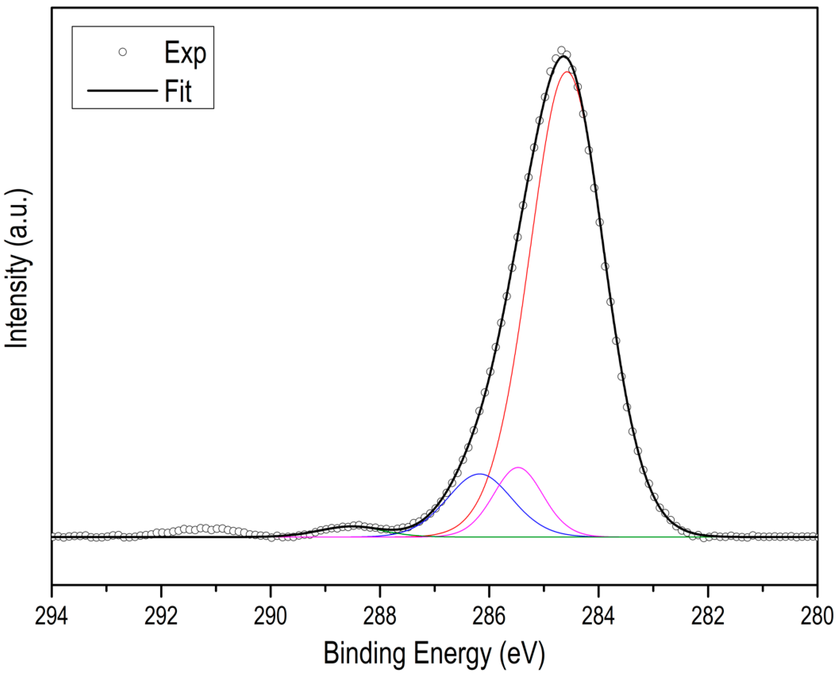
| Sample | NTotal (at.%) | NPyridinic (at.%) | NPyrrolic (at.%) | NQuaternary (at.%) |
|---|---|---|---|---|
| ZIF8C_600_2l | 25 | 17.6 | 6.6 | 0.8 |
| ZIF8C_700_2l | 19.0 | 9.9 | 8.1 | 1 |
| ZIF8C_800_2l | 11.5 | 7.2 | 3.4 | 0.9 |
| ZIF8C_900_2l | 4.0 | 3.1 | 0.2 | 0.7 |
| ZIF67C_600_2l | 20.5 | 13 | 6 | 1 |
| ZIF67C_700_2l | 17.3 | 9.6 | 7,3 | 1.4 |
| ZIF67C_800_2l | 11.2 | 7.1 | 3.2 | 0.9 |
| ZIF67C_900_2l | 5.2 | 4.0 | 0.4 | 0.8 |
Publisher’s Note: MDPI stays neutral with regard to jurisdictional claims in published maps and institutional affiliations. |
© 2022 by the authors. Licensee MDPI, Basel, Switzerland. This article is an open access article distributed under the terms and conditions of the Creative Commons Attribution (CC BY) license (https://creativecommons.org/licenses/by/4.0/).
Share and Cite
Villalgordo-Hernández, D.; Grau-Atienza, A.; García-Marín, A.A.; Ramos-Fernández, E.V.; Narciso, J. Manufacture of Carbon Materials with High Nitrogen Content. Materials 2022, 15, 2415. https://doi.org/10.3390/ma15072415
Villalgordo-Hernández D, Grau-Atienza A, García-Marín AA, Ramos-Fernández EV, Narciso J. Manufacture of Carbon Materials with High Nitrogen Content. Materials. 2022; 15(7):2415. https://doi.org/10.3390/ma15072415
Chicago/Turabian StyleVillalgordo-Hernández, David, Aida Grau-Atienza, Antonio A. García-Marín, Enrique V. Ramos-Fernández, and Javier Narciso. 2022. "Manufacture of Carbon Materials with High Nitrogen Content" Materials 15, no. 7: 2415. https://doi.org/10.3390/ma15072415