
MgO–ZrO2 Ceramic Composites for Silicomanganese Production


 ,
,  , , ,
, , , 

Abstract
:1. Introduction
2. Materials and Methods
2.1. Materials
2.2. Sample Preparation
2.3. Methods
2.3.1. Microstructural Analysis
2.3.2. Morphological Analysis
2.3.3. Mechanical Properties
2.3.4. Chemical State Analyses
2.3.5. Chemical Properties
3. Results and Discussion
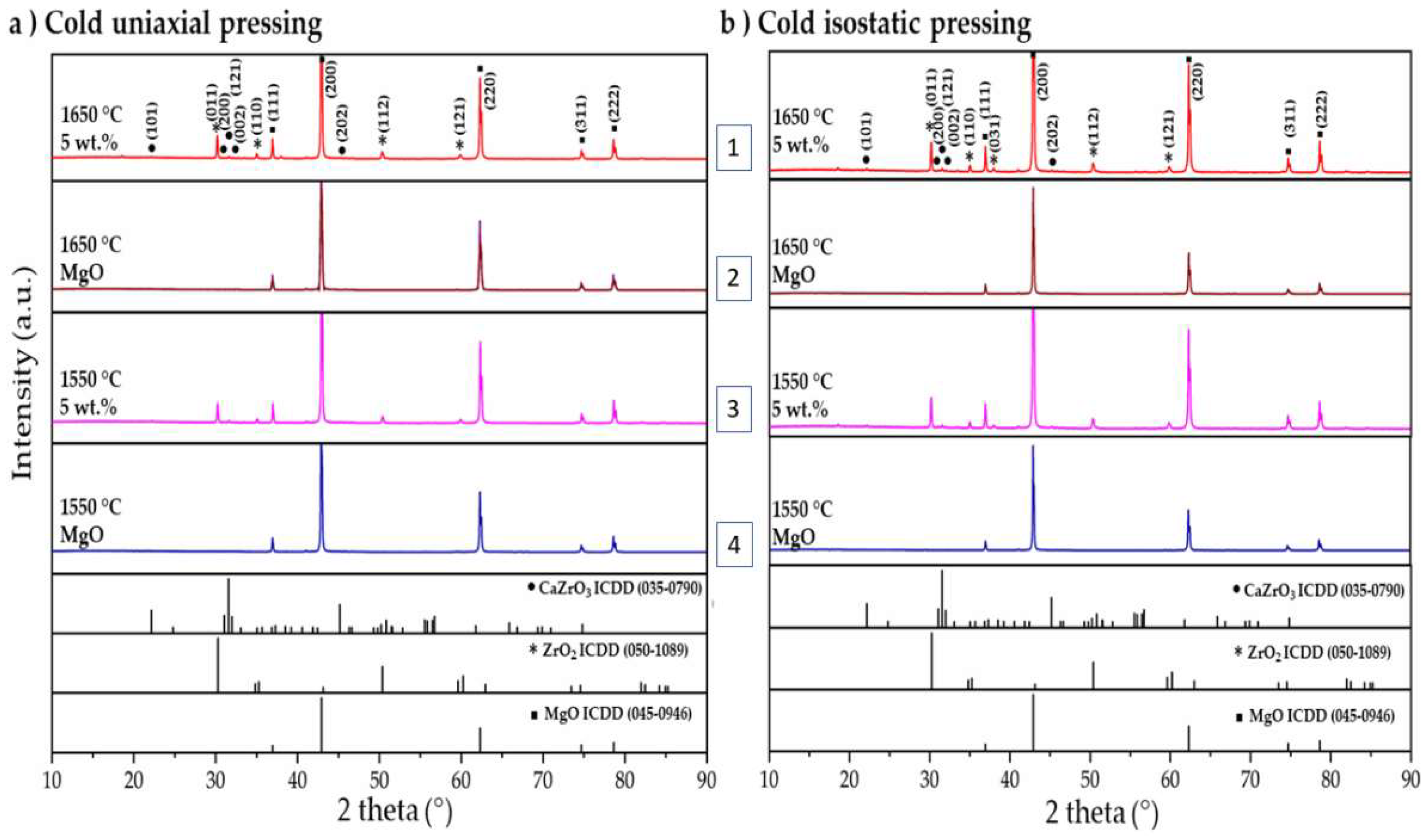
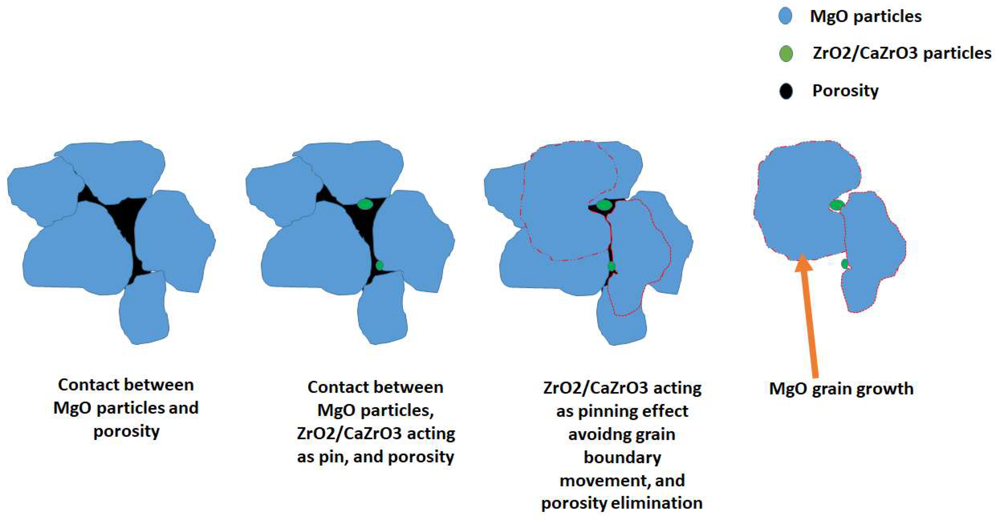
3.1. Microstructural Analysis
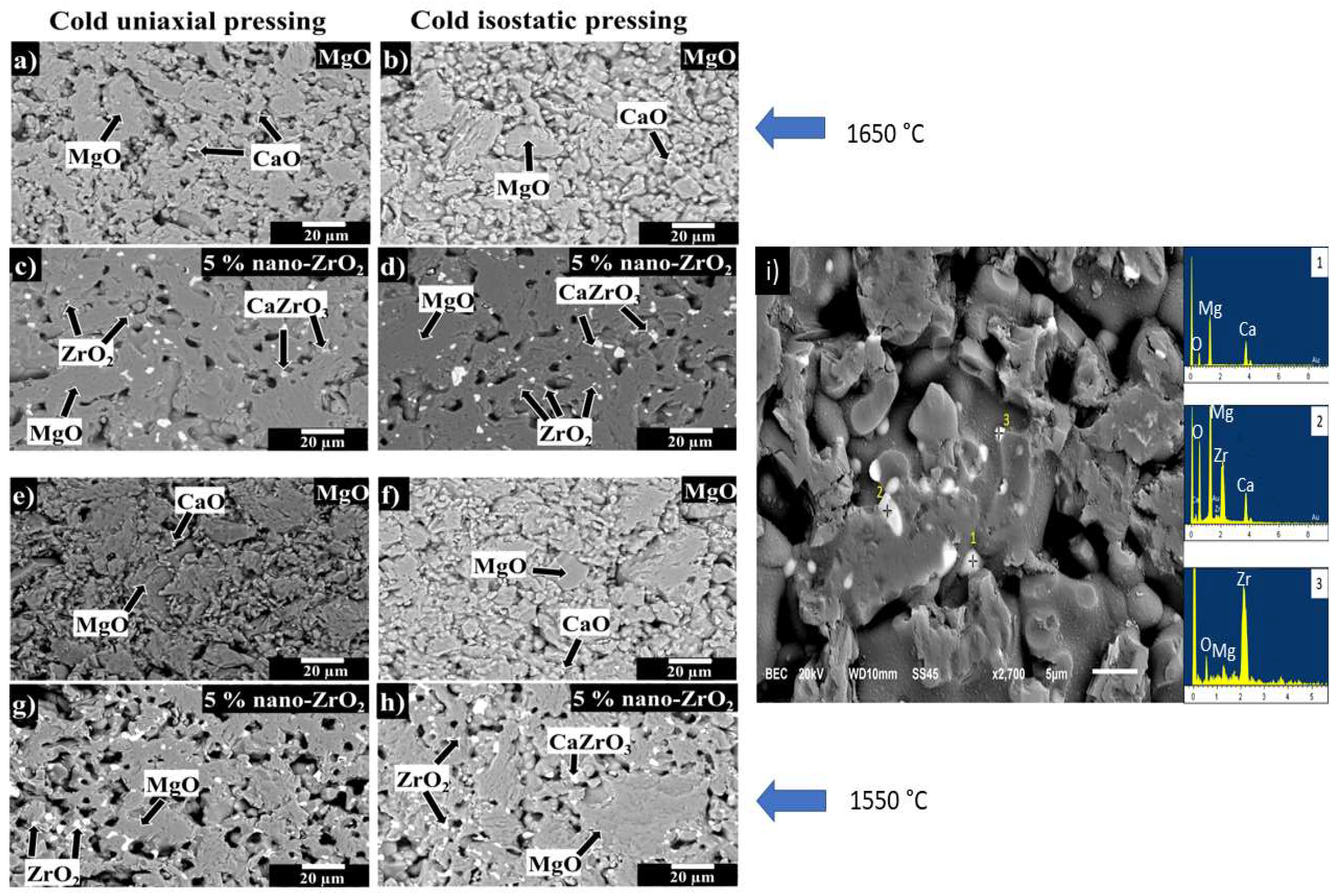
3.2. Morphological Analyses
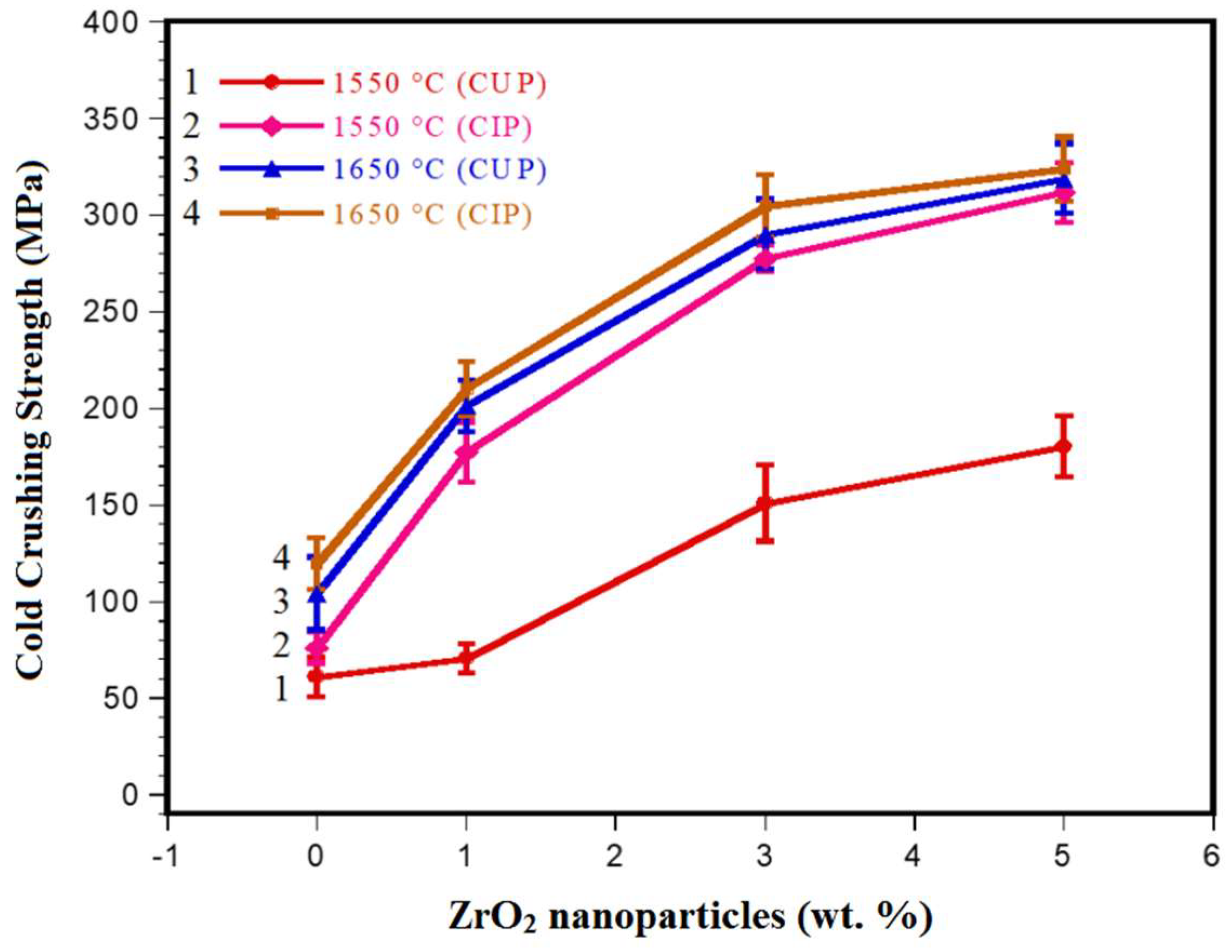
3.3. Mechanical Properties
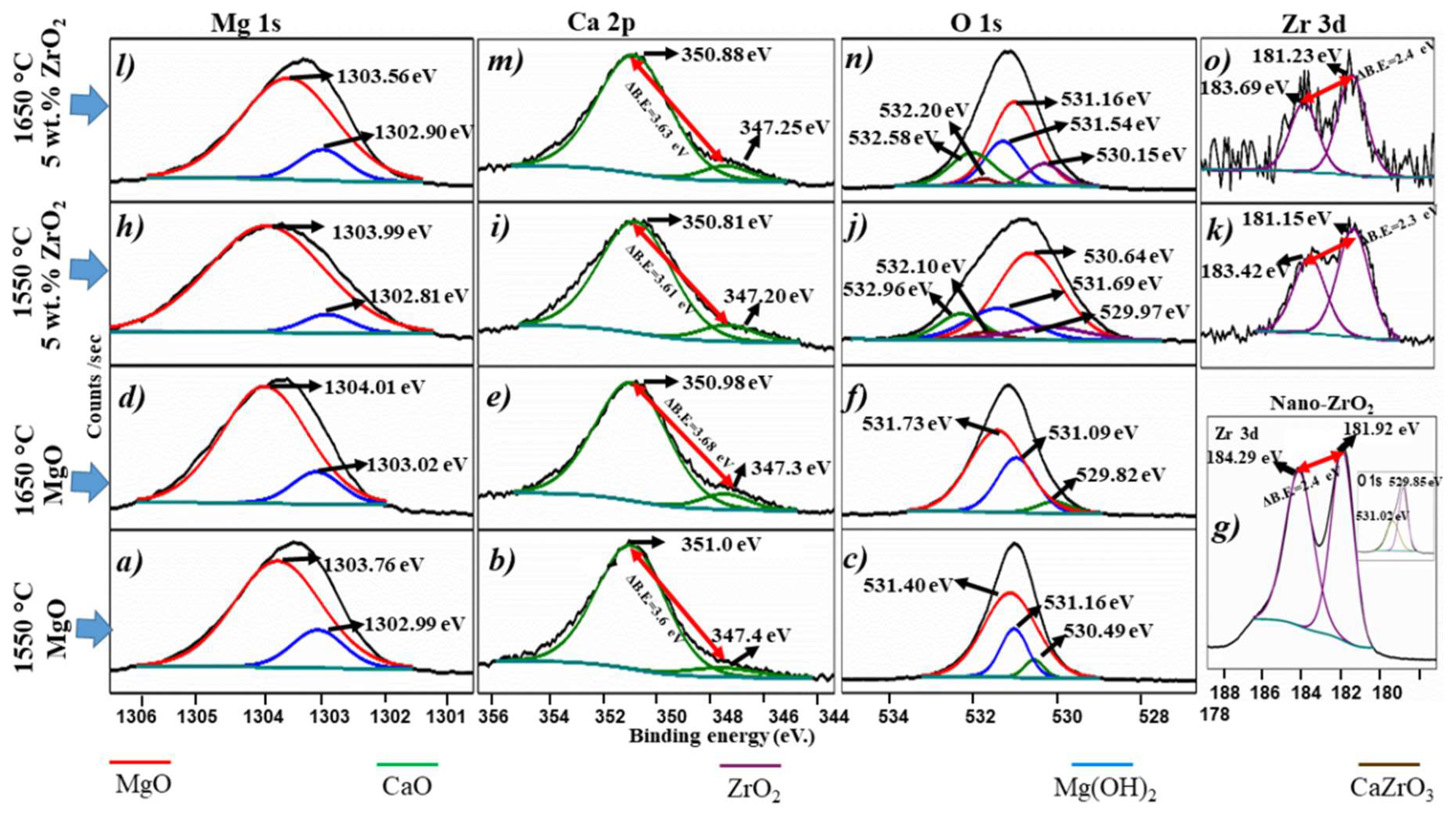
3.4. Chemical States Analyses
3.5. Chemical Properties
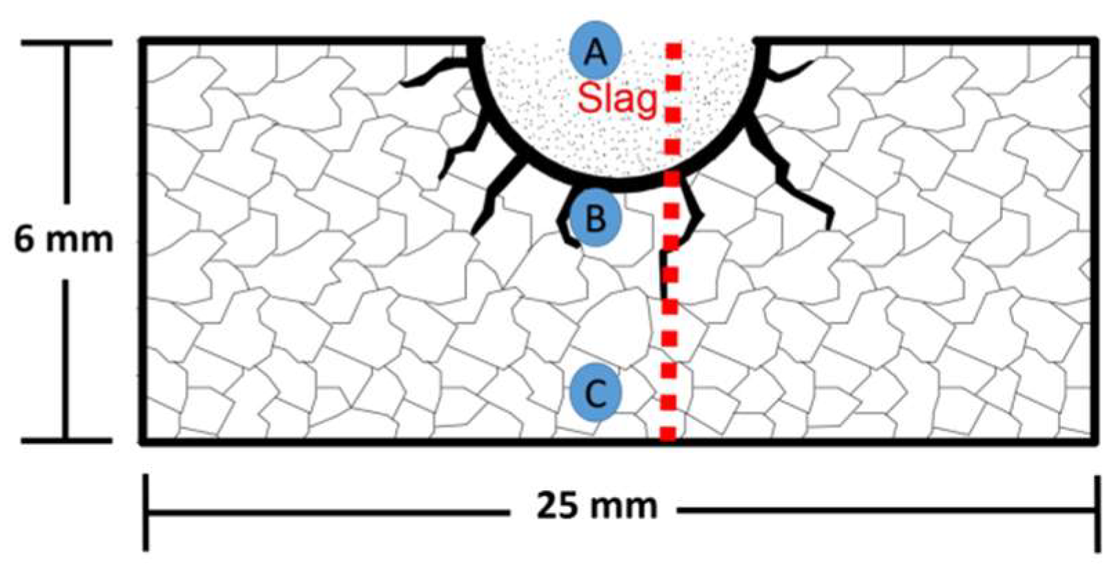
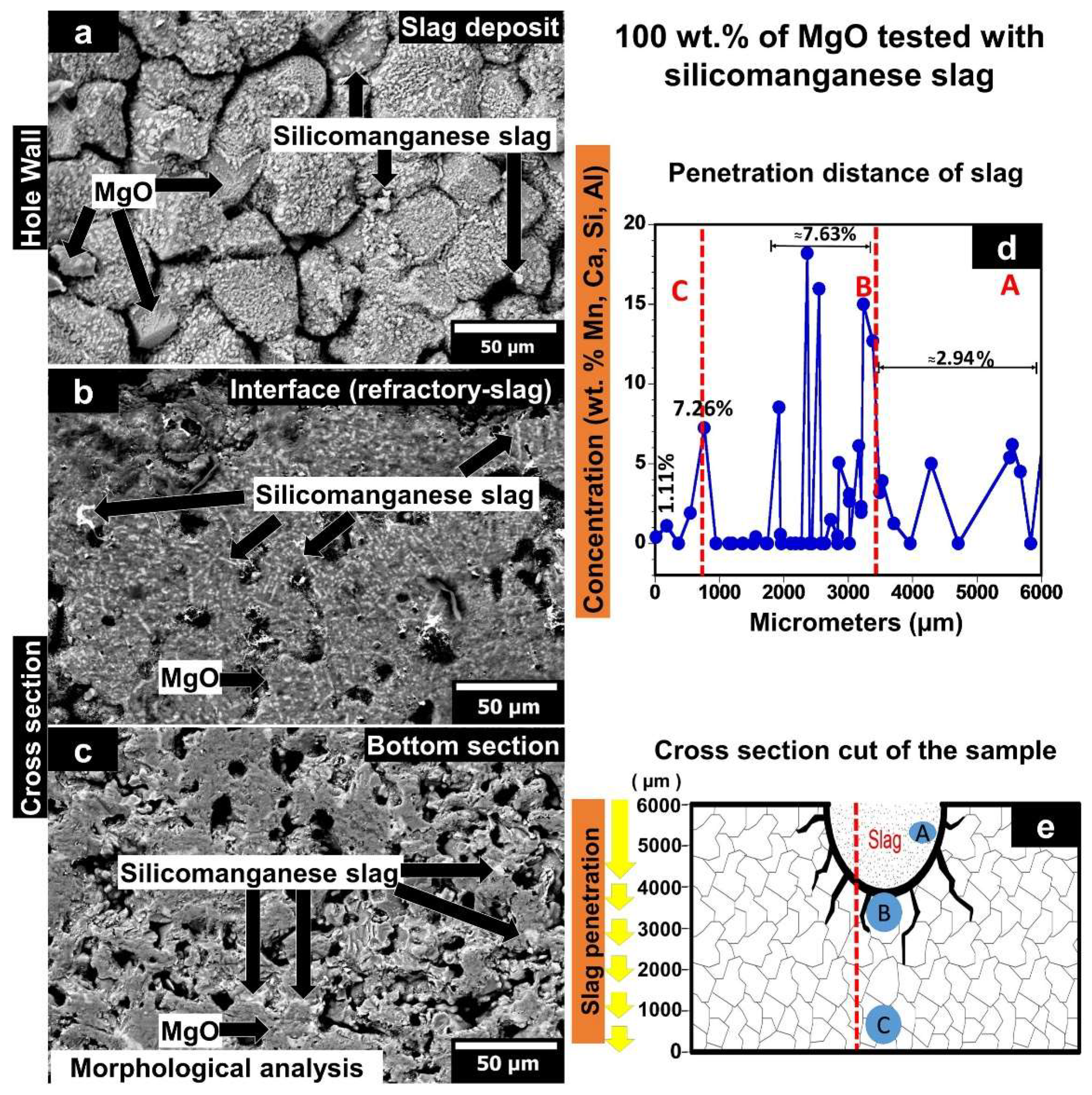
3.5.1. MgO Sample Tested with Silicomanganese Slag
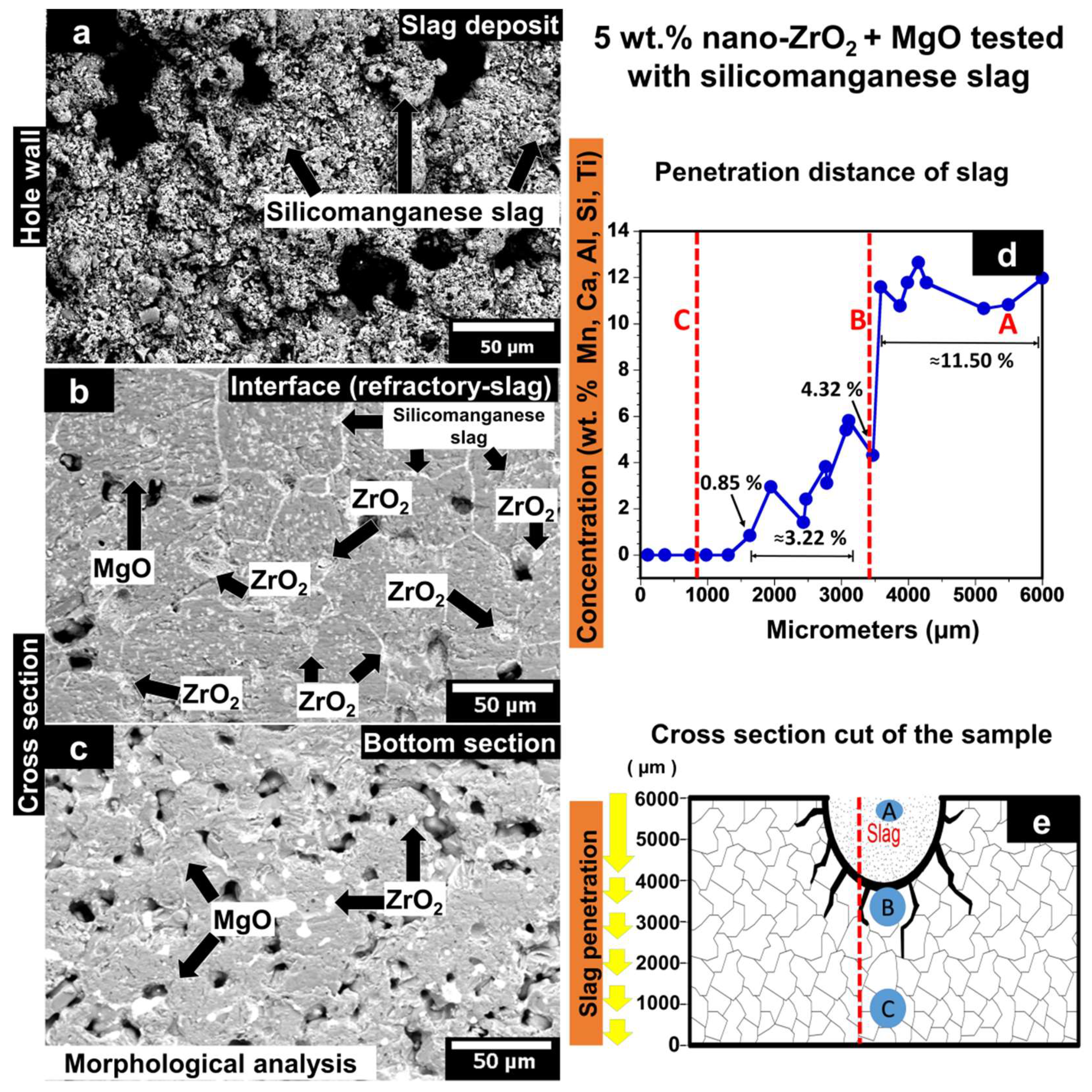
3.5.2. MgO Containing 5 wt.% of ZrO2 Nanoparticles Tested with Silicomanganese Slag
4. Conclusions
Author Contributions
Funding
Institutional Review Board Statement
Informed Consent Statement
Data Availability Statement
Acknowledgments
Conflicts of Interest
References
- Walker, H. Handbook of Refractory Practice; Harbinson-Walker: Pittsburgh, PA, USA, 1979. [Google Scholar]
- Banerjee, S. Properties of refractories. In Refractories Handbook; Schacht, C., Ed.; CRC Press: New York, NY, USA, 2004; pp. 1–10. [Google Scholar]
- Verdeja, L.F.; Sancho, J.P.; Ballester, A.; González, R. Refractory and Ceramic Materials; Síntesis: Madrid, Spain, 2014. [Google Scholar]
- Cardarelli, F. Ceramics, refractories, and glasses. In Materials Handbook: A Concise Desktop Reference; Cardarelli, F., Ed.; Springer: London, UK, 2008; pp. 593–689. [Google Scholar]
- Sadik, C.; Moudden, O.; El Bouari, A.; El Amranic, A.I.-E. Review on the elaboration and characterization of ceramics refractories based on magnesite and dolomite. J. Asian Ceram. Soc. 2016, 4, 219–233. [Google Scholar] [CrossRef] [Green Version]
- Horcksmans, L.; Nielsen, P.; Dierckx, P.; Ducastel, A. Recycling of refractory bricks used in steelmaking: A review. Resour. Conserv. Recycl. 2019, 140, 297–304. [Google Scholar] [CrossRef]
- Verdeja, J.I.; Fernández-González, D.; Verdeja, L.F. Operations and Basic Processes in Ironmaking; Springer: Cham, Switzerland, 2020. [Google Scholar] [CrossRef]
- Verdeja, L.F.; Fernández-González, D.; Verdeja, J.I. Operations and Basic Processes in Steelmaking; Springer: Cham, Switzerland, 2021. [Google Scholar] [CrossRef]
- Olsen, S.E.; Tangstad, M.; Lindstad, T. Production of Manganese Ferroalloys; Tapir Academic Press: Trondheim, Norway, 2007. [Google Scholar]
- Thomas, K.; Gunderwar, C.S. Manganese Ore: Vision 2020 and Beyond; IBM Press: Nagpur, India, 2014. [Google Scholar]
- Steenkamp, J.D.; Pistorius, P.C.; Tangstad, M. Chemical wear analysis of a tap-hole on a SiMn production furnace. J. S. Afr. Inst. Min. Metal. 2015, 115, 199–208. [Google Scholar] [CrossRef] [Green Version]
- Steenkamp, J.D.; Gous, J.P.; Pistorious, P.; Tangstad, M.; Zietsman, J.H. Wear analysis of a tap-hole from A SiMn production furnace. In Furnace Tapping Conference 2014; Steenkamp, J.D., Ed.; The Southern African Institute of Mining and Metallurgy: Johannesburg, South Africa, 2014; pp. 51–64. [Google Scholar]
- Sutherland, J.J.; Gous, J.P. Managing the tap-hole life-cycle at five submerged arc furnaces producing silicomanganese at trasalloys. J. S. Afr. I. Min. Met. 2019, 119, 563–571. [Google Scholar] [CrossRef]
- Banda, W.K.; Steenkamp, J.D.; Matinde, E. An investigation into the wear mechanisms of carbon- and silicon carbide-based refractory materials by silicomanganese alloy. J. S. Afr. Inst. Min. Metal. 2020, 120, 333–344. [Google Scholar] [CrossRef]
- Borges, R.A.A.; Lenz e Silva, G.F.B. A statistical and post-mortem study of wear and performance of MgO-C resin bonded refractories used on the slag line ladle of a basic oxygen steelmaking plant. Eng. Fail. Anal. 2017, 78, 161–168. [Google Scholar] [CrossRef]
- Han, B.; Ke, C.; Wei, Y.; Yan, W.; Wang, C.; Chen, F.; Li, N. Degradation of MgO–C refractories corroded by SiO2–Fe2O3–V2O5–TiO2–MnO–MgO slag. Ceram. Int. 2015, 41, 10966–10973. [Google Scholar] [CrossRef]
- Gómez, C.; Castillo, G.A.; Rodríguez, E.A.; Vázquez-Rodríguez, F.J.; López-Perales, J.F.; Aguilar-Martínez, J.A.; Fernández-González, D.; García-Quiñonez, L.V.; Das-Roy, T.K.; Verdeja, L.F. Development of an ultra-low carbon MgO refractory doped with α-Al2O3 nanoparticles for the steelmaking Industry: A microstructural and thermo-mechanical study. Materials 2020, 13, 715. [Google Scholar] [CrossRef] [PubMed] [Green Version]
- Muñoz, V.; Galliano, P.G.; Brandaleze, E.; Martínez, A.G.T. Chemical wear of Al2O3–MgO–C bricks by air and basic slag. J. Eur. Ceram. Soc. 2015, 35, 1621–1635. [Google Scholar] [CrossRef]
- Chen, L.; Guo, M.; Shi, H.; Scheunis, L.; Jones, P.T.; Blanpain, B.; Malfliet, A. The influence of ZnO in fayalite slag on the degradation of magnesia-chromite refractories during secondary Cu smelting. J. Eur. Ceram. Soc. 2015, 35, 2641–2650. [Google Scholar] [CrossRef]
- Chen, L.; Guo, M.; Shi, H.; Huang, S.; Jones, P.T.; Blanpain, B.; Malfliet, A. Effect of ZnO level in secondary copper smelting slags on slag/magnesia-chromite refractory interactions. J. Eur. Ceram. Soc. 2016, 36, 1821–1828. [Google Scholar] [CrossRef]
- Chen, L.; Li, S.; Jones, P.T.; Guo, M.; Blanpain, B.; Malfliet, A. Identification of magnesia–chromite refractory degradation mechanisms of secondary copper smelter linings. J. Eur. Ceram. Soc. 2016, 36, 2119–2132. [Google Scholar] [CrossRef]
- Jeon, J.; Kang, Y.; Park, J.H.; Chung, Y. Corrosion-erosion behavior of MgAl2O4 spinel refractory in contact with high MnO slag. Ceram. Int. 2017, 43, 15074–15079. [Google Scholar] [CrossRef]
- Rodríguez, E.A.; Castillo, G.A.; Das, T.K.; Puente-Ornelas, R.; González, Y.; Arato, A.M.; Aguilar-Martínez, J.A. MgAl2O4 spinel as an effective ceramic bonding in a MgO–CaZrO3 refractory. J. Eur. Ceram. Soc. 2013, 33, 2767–2774. [Google Scholar] [CrossRef]
- Ceylantekin, R.; Aksel, C. Improvements on corrosion behaviours of MgO–spinel composite refractories by addition of ZrSiO4. J. Eur. Ceram. Soc. 2012, 32, 727–736. [Google Scholar] [CrossRef]
- Szczerba, J. Chemical corrosion of basic refractories by cement kiln materials. Ceram. Int. 2010, 36, 1877–1885. [Google Scholar] [CrossRef]
- Aneziris, C.G.; Hubálková, J.; Barabás, J. Microstructure evaluation of MgO–C refractories with TiO2- and Al-additions. J. Eur. Ceram. Soc. 2007, 27, 73–78. [Google Scholar] [CrossRef]
- Ding, X.; Zhao, H.; Xiang, Z.; Zhang, H.; He, Q.; Li, J. Effect of hercynite content on the properties of magnesia-spinel composite refractories sintered in different atmospheres. Ceram. Int. 2016, 42, 19058–19062. [Google Scholar] [CrossRef]
- Serena, S.; Sainz, M.A.; Caballero, A. Corrosion behavior of MgO/CaZrO3 refractory matrix by Clinker. J. Eur. Ceram. Soc. 2004, 24, 2399–2406. [Google Scholar] [CrossRef]
- Kahrizsangi, S.G.; Nemati, A.; Shahraki, A.; Farooghi, M. Effect of nano-sized Fe2O3 on microstructure and hydration resistance of MgO-CaO refractories. Int. J. Nanosci. Nanotechnol. 2016, 12, 19–26. [Google Scholar]
- Gómez-Rodríguez, C.; Das, T.K.; Shaji, S.; Castillo-Rodríguez, G.A.; García-Quiñonez, L.; Rodríguez, E.; González, J.O.; Aguilar-Martínez, J.A. Effect of addition of Al2O3 and Fe2O3 nanoparticles on the microstructural and physico-chemical evolution of dense magnesia composite. Ceram. Int. 2015, 41, 7751–7758. [Google Scholar] [CrossRef]
- Ghasemi, S.; Gheisari, H.; Boroujerdnia, M. Effect of micro and nano-Al2O3 addition on the microstructure and properties of MgO-C refractory ceramic composite. Mater. Chem. Phys. 2016, 189, 545–551. [Google Scholar] [CrossRef]
- Shahraki, A.; Ghasemi-Kahrizsangi, S.A.; Nemati, A. Performance improvement of MgO-CaO refractories by the addition of nano-sized Al2O3. Mater. Chem. Phys. 2017, 198, 354–359. [Google Scholar] [CrossRef]
- Dudczig, S.; Veres, D.; Aneziris, C.G.; Sierra, E.; Steinbrech, R.W. Nano- and micrometre additions of SiO2, ZrO2 and TiO2 in fine grained alumina refractory ceramics for improved thermal shock performance. Ceram. Int. 2012, 38, 2011–2019. [Google Scholar] [CrossRef]
- Ghasemi-Kahrizsangi, S.; Sedeh, M.B.; Dehsheikh, H.G.; Shahraki, A.; Farooghi, M. Densification and properties of ZrO2 nanoparticles added magnesia-doloma refractories. Ceram. Int. 2016, 42, 15658–15663. [Google Scholar] [CrossRef]
- Dehsheikh, G.H.; Ghasemi-Kahrizsangi, S. Performance improvement of MgO-C refractory bricks by the addition of Nano-ZrSiO4. Mater. Chem. Phys. 2017, 202, 369–376. [Google Scholar] [CrossRef]
- Ghasemi-Kahrizsangi, S.; Karamian, E.; Dehsheikh, H.G. The impact of ZrSiO4 nanoparticles addition on the microstructure and properties of dolomite based refractories. Ceram. Int. 2017, 43, 13932–13937. [Google Scholar] [CrossRef]
- Bag, M.; Adak, S.; Sarkar, R. Study on low carbon containing MgO-C refractory: Use of nano carbon. Ceram. Int. 2012, 38, 2339–2346. [Google Scholar] [CrossRef]
- Dehsheikh, H.G.; Ghasemi-Kahrizsangi, S.; Karamian, E. Addition impact of nano-carbon black on the performance of MgO-CaO compounds. Ceram. Int. 2018, 44, 5524–5527. [Google Scholar] [CrossRef]
- Ghasemi-Kahrizsangi, S.; Dehsheikh, H.G.; Karamian, E.; Boroujerdnia, M.; Payandeh, K. Effect of MgAl2O4 nanoparticles addition on the densification and properties of MgO-CaO refractories. Ceram. Int. 2017, 43, 5014–5019. [Google Scholar] [CrossRef]
- Ghasemi-Kahrizsangi, S.; Dehsheikh, H.G.; Karamian, E. Impact of Titania nanoparticles addition on the microstructure and properties of MgO-C refractories. Ceram. Int. 2017, 43, 15472–15477. [Google Scholar] [CrossRef]
- Ghasemi-Kahrizsangi, S.; Shahraki, A.; Farooghi, M. Effect of Nano-TiO2 Additions on the Densification and Properties of Magnesite-Dolomite Ceramic Composites. Iran J. Sci. Technol. Trans. A Sci. 2018, 42, 567–575. [Google Scholar] [CrossRef]
- Zargar, H.R.; Oprea, C.; Oprea, G.; Troczynski, T. The effect of nano-Cr2O3 on solid-solution assisted sintering of MgO refractories. Ceram. Int. 2012, 38, 6235–6241. [Google Scholar] [CrossRef]
- Ghasemi-Kahrizsangi, S.; Dehsheikh, H.G.; Boroujerdnia, M. MgO-CaO-Cr2O3 composition as a novel refractory brick: Use of Cr2O3 nanoparticles. Bol. Soc. Esp. Ceram. V. 2017, 56, 83–89. [Google Scholar] [CrossRef]
- Dehsheikh, H.G.; Ghasemi-Kahrizsangi, S. The influence of silica nanoparticles addition on the physical, mechanical, thermo-mechanical as well as microstructure of Mag-Dol refractory composites. Ceram. Int. 2017, 43, 16780–16786. [Google Scholar] [CrossRef]
- Puertas, F. Cementos de escorias activadas alcalinamente: Situación actual y perspectivas de futuro. Mater. Construcc. 1995, 45, 53–64. [Google Scholar] [CrossRef] [Green Version]
- Ballester, A.; Verdeja, L.F.; Sancho, J.P. Metalurgia Extractiva: Fundamentos, 1st ed.; Síntesis: Madrid, Spain, 2000; Volume I. [Google Scholar]
- Gómez-Rodríguez, C.; Fernández-González, D.; García-Quiñonez, L.V.; Castillo-Rodríguez, G.A.; Aguilar-Martínez, J.A.; Verdeja, L.F. MgO Refractory Doped with ZrO2 nanoparticles: Influence of cold isostatic and uniaxial pressing and sintering temperature in the physical and chemical properties. Metals 2019, 9, 1297. [Google Scholar] [CrossRef] [Green Version]
- Ashby, J.M. Engineering Materials 2: An Introduction to Microstructures, Processing and Design; Butterworth-Heinemann: Burlington, VT, USA, 2005. [Google Scholar]
- Stevens, R. Magnesium Elektron, Zirconia and Zirconia Ceramics; Magnesium Elektron: Manchester, UK, 1986. [Google Scholar]
- Wolten, G.M. Diffusionless phase transformations in zirconia and hafnia. J. Am. Ceram. Soc. 1963, 46, 418–422. [Google Scholar] [CrossRef]
- Platt, P.; Frankel, P.; Gass, M.; Howells, R.; Preuss, M. Finite element analysis of the tetragonal to monoclinic phase transformation during oxidation of zirconium alloys. J. Nucl. Mater. 2014, 454, 290–297. [Google Scholar] [CrossRef]
- Bailey, J.E. The monoclinic-tetragonal transformation and associated twinning in thin films of zirconia. Proc. R. Soc. Lond. Ser. A Math. Phys. Sci. 1964, 279, 395–412. [Google Scholar] [CrossRef]
- Qingping, S.; Shouwen, Y.; Kehchih, H. A micromechanics constitutive model for pure dilatant martensitic transformation of ZrO2-containing ceramics. Acta Mech. Sin. 1990, 6, 141–150. [Google Scholar] [CrossRef]
- Stam, G.T.; Van der Giessen, E.; Meijers, P. Effect of transformation-induced shear strains on crack growth in zirconia-containing ceramics. Int. J. Solids Struct. 1994, 31, 1923–1948. [Google Scholar] [CrossRef] [Green Version]
- Moulder, J.F. Handbook of X-ray Photoelectron Spectroscopy: A Reference Book of Standard Spectra for Identification and Interpretation of XPS Data; Physical Electronics: Chanhassen, MN, USA, 1995. [Google Scholar]
- Reddy, C.V.; Babu, B.; Reddy, I.N.; Shim, J. Synthesis and characterization of pure tetragonal ZrO2 nanoparticles with enhanced photocatalytic activity. Ceram. Int. 2018, 44, 6940–6948. [Google Scholar] [CrossRef]
- García, L.V.; Mendivil, M.I.; Roy, T.K.; Castillo, G.A.; Shaji, S. Laser sintering of magnesia with nanoparticles of iron oxide and aluminum oxide. Appl. Surf. Sci. 2015, 336, 59–66. [Google Scholar] [CrossRef]
- García-Quiñonez, L.V.; Mendivil-Palma, M.I.; Das Roy, T.K.; Castillo-Rodríguez, G.A.; Gómez-Rodríguez, C.; Fernández-González, D.; Shaji, S. Effects of irradiation energy and nanoparticle concentrations on the structure and morphology of laser sintered magnesia with alumina and iron oxide nanoparticles. Ceram. Int. 2020, 46, 7850–7860. [Google Scholar] [CrossRef]
- Koirala, R.; Gunugunuri, K.R.; Pratsinis, S.E.; Smirniotis, P.G. Effect of zirconia doping on the structure and stability of CaO-based sorbents for CO2 capture during extended operating cycles. J. Phys. Chem. C 2011, 115, 24804–24812. [Google Scholar] [CrossRef]
- Cabello, G.; Lillo, L.; Caro, C.; Buono-Core, G.E.; Chornik, B.; Flores, M.; Carrasco, C.; Rodríguez, C.A. Photochemical synthesis of AZrO3−X thin films (A = Ba, Ca and Sr) and their characterization. Ceram Int. 2014, 40, 7761–7768. [Google Scholar] [CrossRef]
- Inoue, Y.; Yasumori, I. Catalysis by alkaline earth metal oxides. III. X-ray photoelectron spectroscopic study of catalytically active MgO, CaO, and BaO surfaces. Bull. Chem. Soc. Jpn. 1984, 54, 1505–1510. [Google Scholar] [CrossRef] [Green Version]
- Shah, D.; Bahr, S.; Dietrich, P.; Mayer, M.; Thiben, A.; Linford, M.R. Zirconium oxide particles, by near-ambient pressure XPS. Surf. Sci. Spectra. 2019, 26, 024001. [Google Scholar] [CrossRef]
- Bumajdad, A.; Nazeer, A.A.; Al Sagheer, F.; Nahar, S.; Zaki, M.I. Controlled synthesis of ZrO2 nanoparticles with tailored size, morphology and crystal phases via organic/inorganic hybrid films. Sci. Rep. 2018, 8, 3695. [Google Scholar] [CrossRef] [Green Version]
- Sosulnikov, M.I.; Teterin, Y.A. X-ray photoelectron studies of Ca, Sr and Ba and their oxides and carbonates. J. Electron Spectrosc. 1992, 59, 111–126. [Google Scholar] [CrossRef]
- Reddy, G.K.; Quillin, S.; Smirniotis, P. Influence of the synthesis method on the structure and CO2 adsorption properties of Ca/Zr sorbents. Energ. Fuel. 2014, 28, 3292–3299. [Google Scholar] [CrossRef]
- Zhang, J.Y.; Wu, Z.L.; Wang, S.G.; Zhao, C.J.; Yang, G.; Zhang, S.L.; Liu, Y.; Liu, S.; Teng, J.; Yu, G.H. Effect of interfacial structures on anomalous Hall behavior in perpendicular Co/Pt multilayers. Appl. Phys. Left. 2013, 102, 102404. [Google Scholar] [CrossRef]
- Wan, Y.; Samundsett, C.; Bullock, J.; Hettick, M.; Allen, T.; Yan, D.; Peng, J.; Wu, Y.; Cui, J.; Javey, A.; et al. Conductive and stable magnesium oxide electron-selective contacts for efficient silicon solar cells. Adv. Energy Mater. 2017, 7, 1601863. [Google Scholar] [CrossRef]
- Haycock, D.E.; Kasrai, M.; Nicholls, C.J.; Urch, D.S. The electronic structure of magnesium hydroxide (brucite) using X-ray emission, X-ray photoelectron, and auger spectroscopy. J. Chem. Soc. Dalton Trans. 1978, 12, 1791–1796. [Google Scholar] [CrossRef]
- Li, W.; Liu, X.; Huang, A.; Chu, P.K. Structure and properties of zirconia (ZrO2) films fabricated by plasma-assisted cathodic arc deposition. J. Phys. D. Appl. Phys. 2007, 40, 2293–2299. [Google Scholar] [CrossRef] [Green Version]
- Rameshan, C.; Li, H.; Anic, K.; Roiaz, M.; Pramhaas, V.; Rameshan, R.; Blume, R.; Hëavecker, M.; Knudsen, J.; Knop-Gericke, A. In Situ NAP-XPS spectroscopy during methane dry reforming on ZrO2/Pt (1 1 1) inverse model catalyst. J. Chem. Soc. Dalton Trans. 2018, 30, 264007. [Google Scholar] [CrossRef]
- Angers, R.; Tremblay, A.; Chaklader, A.C.D. Formation of CaZrO3 by solid-state reaction between CaO and ZrO2. J. Am. Ceram. Soc. 1972, 55, 425. [Google Scholar] [CrossRef]
- Serena, S. Modelización Termodinámica y Cálculo del Diagrama de Equilibrio de Fases ZrO2-CaO-MgO: Aplicación al Diseño y Obtención de Materiales de MgO-CaZrO3. Ph.D. Thesis, Universidad Autónoma de Madrid, Facultad de Ciencias and Instituto de Cerámica y Vidrio (C.S.I.C.), Madrid, Spain, 21 March 2002. Available online: http://hdl.handle.net/10486/673998 (accessed on 10 March 2022).
- De la Lastra, C.B.; Pena, P.; Obregón, A.; Rodríguez-Galicia, J.L. Mechanical behaviour of MgO-CaZrO3-based refractories for cement kilns. Adv. Sci. Technol. 2010, 70, 47–52. [Google Scholar] [CrossRef]
- Schafföner, S.; Aneziris, C.G.; Berek, H.; Hubálková, J.; Priese, A. Fused calcium zirconate for refractory applications. J. Eur. Ceram. Soc. 2013, 33, 3411–3418. [Google Scholar] [CrossRef]
- Hou, Z.F. Ab initio calculations of elastic modulus and electronic structures of cubic CaZrO3. Phys. B Condens. Matter. 2008, 403, 2624–2628. [Google Scholar] [CrossRef]
- Szczerba, J. Modyfikowane magnezjowe materiały ogniotrwałe. Pol. Tow. Ceram. 2007, 99, 1–204. [Google Scholar]
- Silva, A.; Booth, F.; Garrido, L.; Aglietti, E.; Pena, P.; Baudín, C. Sliding wear of CaZrO3-MgO composites against ZrO2 and steel. J. Eur. Ceram. Soc. 2017, 37, 297–303. [Google Scholar] [CrossRef]
- Szczerba, J. Wyroby magnezjowe z cyrkonianem wapnia w osnowie. Mater. Ceram. 2009, 61, 7–11. [Google Scholar]
- Lang, J.F.; You, J.G.; Zhang, X.F.; Luo, X.D.; Zheng, S.Y. Effect of MgO on thermal shock resistance of CaZrO3 ceramic. Ceram. Int. 2018, 44, 22176–22180. [Google Scholar] [CrossRef]
- Ewais, E.M.M.; Bayoumi, I.M.I. Fabrication of MgO-CaZrO3 refractory composites from Egyptian dolomite as a clinker to rotary cement kiln lining. Ceram. Int. 2018, 44, 9236–9246. [Google Scholar] [CrossRef]
- Pena, P.; De Aza, S. Compatibility relations of Al2O3 in the system ZrO2-Al2O3-SiO2-CaO. J. Am. Ceram. Soc. 1984, 67, C3–C5. [Google Scholar]

| Sintering Temperature | Pressing Method | Batch Composition | Physical Properties | |||
|---|---|---|---|---|---|---|
| Simple Code | ZrO2 Nanoparticles (wt.%) | MgO (wt.%) | Density (g/cm3) | Porosity (%) | ||
| 1550 °C | CUP Batch 1 | XL1 | 0 | 100 | 2.62 | 28.46 |
| XL2 | 1 | 99 | 2.66 | 27.21 | ||
| XL3 | 3 | 97 | 2.88 | 20.83 | ||
| XL4 | 5 | 95 | 2.89 | 20.90 | ||
| 1550 °C | CUP + CIP Batch 3 | XL5 | 0 | 100 | 2.67 | 27.03 |
| XL6 | 1 | 99 | 2.67 | 26.79 | ||
| XL7 | 3 | 97 | 2.90 | 19.69 | ||
| XL8 | 5 | 95 | 2.90 | 20.24 | ||
| 1650 °C | CUP Batch 2 | XL9 | 0 | 100 | 2.65 | 27.54 |
| XL10 | 1 | 99 | 2.83 | 21.73 | ||
| XL11 | 3 | 97 | 2.95 | 18.27 | ||
| XL12 | 5 | 95 | 3.01 | 17.22 | ||
| 1650 °C | CUP + CIP Batch 4 | XL13 | 0 | 100 | 2.71 | 26.25 |
| XL14 | 1 | 99 | 2.88 | 20.57 | ||
| XL15 | 3 | 97 | 2.99 | 16.43 | ||
| XL16 | 5 | 95 | 3.06 | 14.49 | ||
| Sample | O 1 s eV | ||||
|---|---|---|---|---|---|
| MgO | Mg (OH)2 | ZrO2 | CaO | CaZrO3 | |
| ZrO2 nanoparticles | 529.85 | ||||
| XL5 | 531.4 | 531.16 | 530.49 | ||
| XL8 | 530.64 | 531.69 | 529.97 | 532.96 | 532.1 |
| XL13 | 531.73 | 531.09 | 529.82 | ||
| XL16 | 531.16 | 531.54 | 530.15 | 532.58 | 532.2 |
| From the literature | 529.2 [58], 530.4 [57,58], 531.2 [61]. | 531.15 [58], 531.5 [58], 531.6 [61], 532.5 [58], | 527.1 [62], 529.7 [63], 530.0 [63]. | 530.10 [64], 532.5 [59]. | 531.9 [65], 532.2 [59] |
| Sample | Mg 1 s eV | Ca 2 p eV | Zr 3 d eV | |||
|---|---|---|---|---|---|---|
| MgO | Mg(OH)2 | CaO 2p1/2 | CaO 2p3/2 | ZrO2 3d3/2 | ZrO2 3d5/2 | |
| ZrO2 nanoparticles | 184.29 | 181.92 | ||||
| XL5 | 1303.76 | 1302.99 | 351.00 | 347.40 | ||
| XL8 | 1303.99 | 1302.81 | 350.81 | 347.20 | 183.42 | 181.15 |
| XL13 | 1304.01 | 1303.02 | 350.98 | 347.30 | ||
| XL16 | 1303.56 | 1302.90 | 350.88 | 347.25 | 183.69 | 181.23 |
| From the literature | 1303.8 [66], 1303.9 [57,58], 1303.4 [67]. | 1301.1 [57], 1301.98 [58], 1302.2 [66], 1302.7 [68]. | 348 [59], 349.7 [64]. 351.0 [59,60]. | 346.5 [59], 347.7 [59]. | 183 [59], 184.9 [69]. | 181.1 [70], 182 [63]. |
Publisher’s Note: MDPI stays neutral with regard to jurisdictional claims in published maps and institutional affiliations. |
© 2022 by the authors. Licensee MDPI, Basel, Switzerland. This article is an open access article distributed under the terms and conditions of the Creative Commons Attribution (CC BY) license (https://creativecommons.org/licenses/by/4.0/).
Share and Cite
Gómez-Rodríguez, C.; García-Quiñonez, L.V.; Aguilar-Martínez, J.A.; Castillo-Rodríguez, G.A.; Rodríguez-Castellanos, E.A.; López-Perales, J.F.; Mendivil-Palma, M.I.; Verdeja, L.F.; Fernández-González, D. MgO–ZrO2 Ceramic Composites for Silicomanganese Production. Materials 2022, 15, 2421. https://doi.org/10.3390/ma15072421
Gómez-Rodríguez C, García-Quiñonez LV, Aguilar-Martínez JA, Castillo-Rodríguez GA, Rodríguez-Castellanos EA, López-Perales JF, Mendivil-Palma MI, Verdeja LF, Fernández-González D. MgO–ZrO2 Ceramic Composites for Silicomanganese Production. Materials. 2022; 15(7):2421. https://doi.org/10.3390/ma15072421
Chicago/Turabian StyleGómez-Rodríguez, Cristian, Linda Viviana García-Quiñonez, Josué Amilcar Aguilar-Martínez, Guadalupe Alan Castillo-Rodríguez, Edén Amaral Rodríguez-Castellanos, Jesús Fernando López-Perales, María Isabel Mendivil-Palma, Luis Felipe Verdeja, and Daniel Fernández-González. 2022. "MgO–ZrO2 Ceramic Composites for Silicomanganese Production" Materials 15, no. 7: 2421. https://doi.org/10.3390/ma15072421
APA StyleGómez-Rodríguez, C., García-Quiñonez, L. V., Aguilar-Martínez, J. A., Castillo-Rodríguez, G. A., Rodríguez-Castellanos, E. A., López-Perales, J. F., Mendivil-Palma, M. I., Verdeja, L. F., & Fernández-González, D. (2022). MgO–ZrO2 Ceramic Composites for Silicomanganese Production. Materials, 15(7), 2421. https://doi.org/10.3390/ma15072421