
Low-Pressure Plasma-Processed Ruthenium/Nickel Foam Electrocatalysts for Hydrogen Evolution Reaction

 and
and 
Abstract
:1. Introduction
2. Experimental Section
2.1. Materials and Regents
2.2. Synthesis of Ru Electrocatalysts
2.3. Characterization
3. Results and Discussion
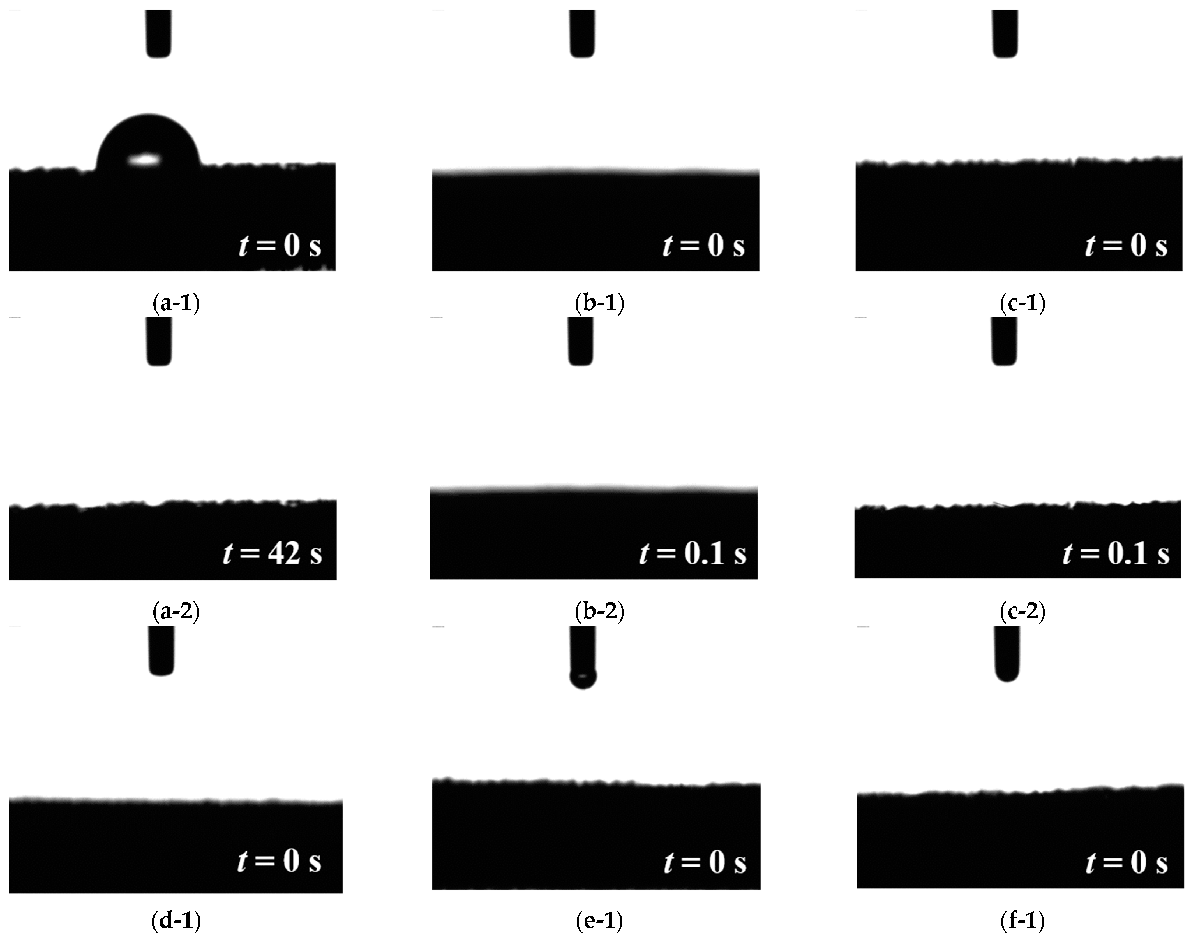
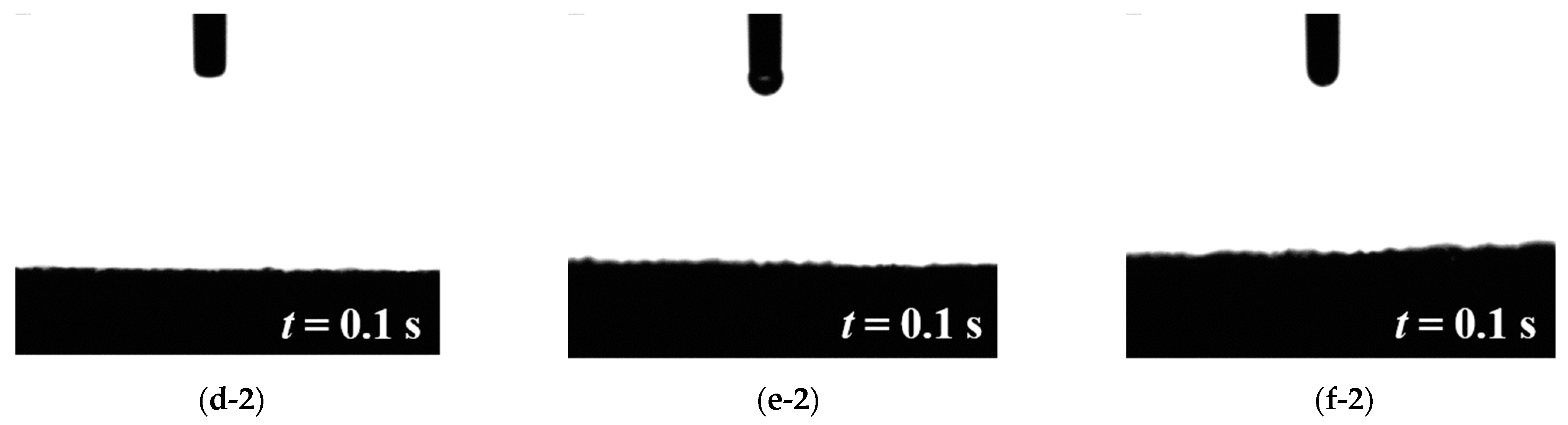
3.1. Water Contact Angle
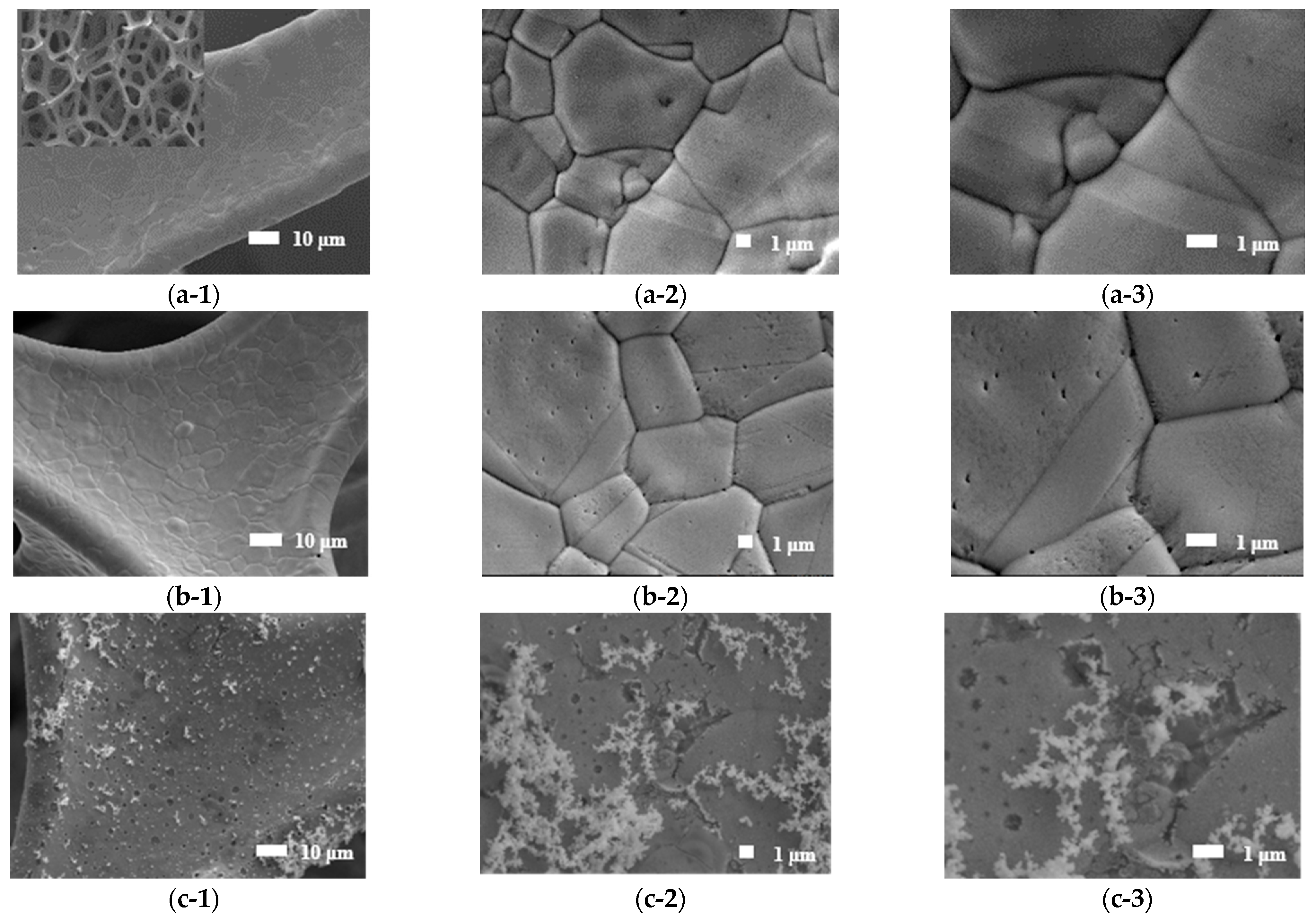
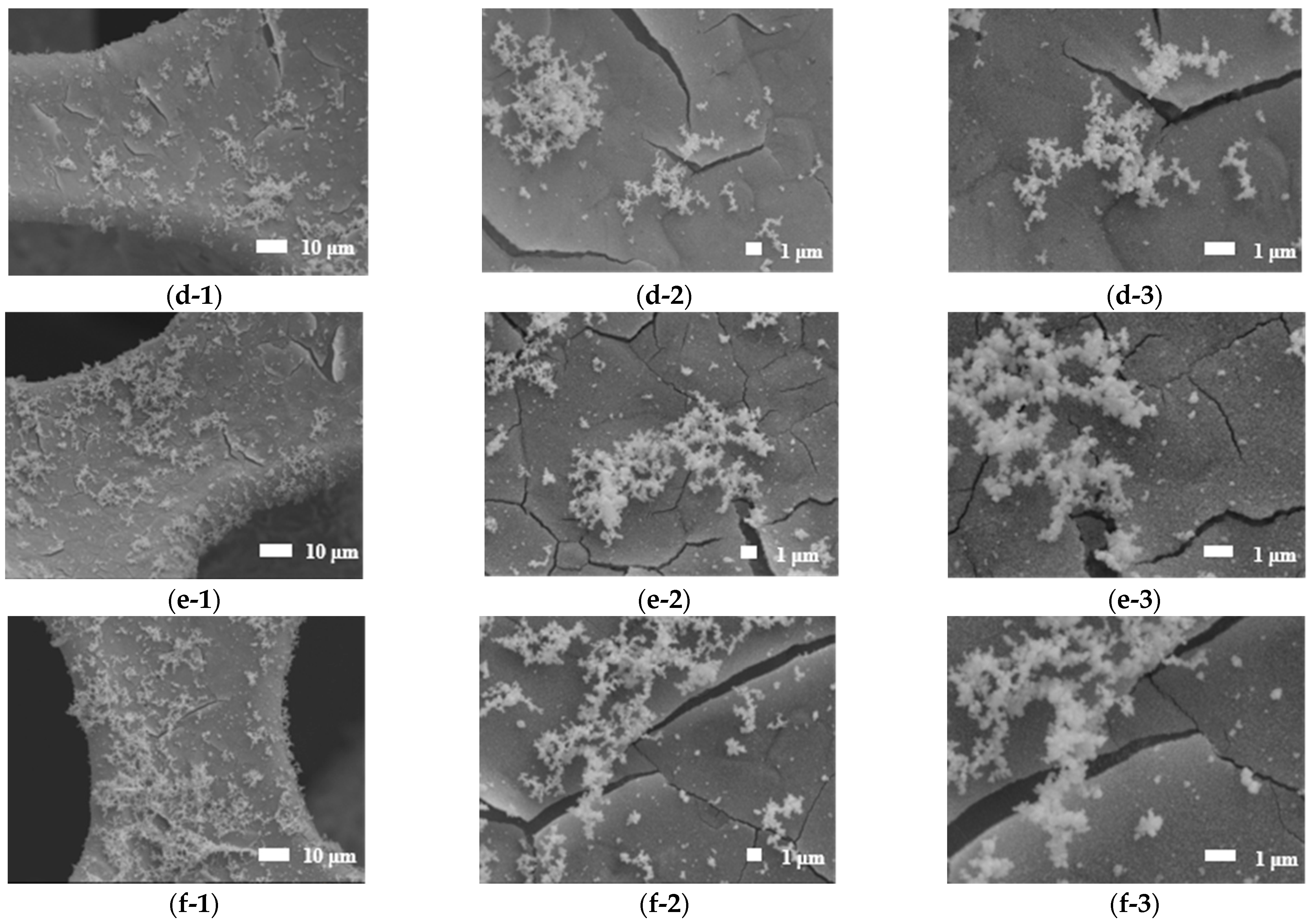
3.2. SEM
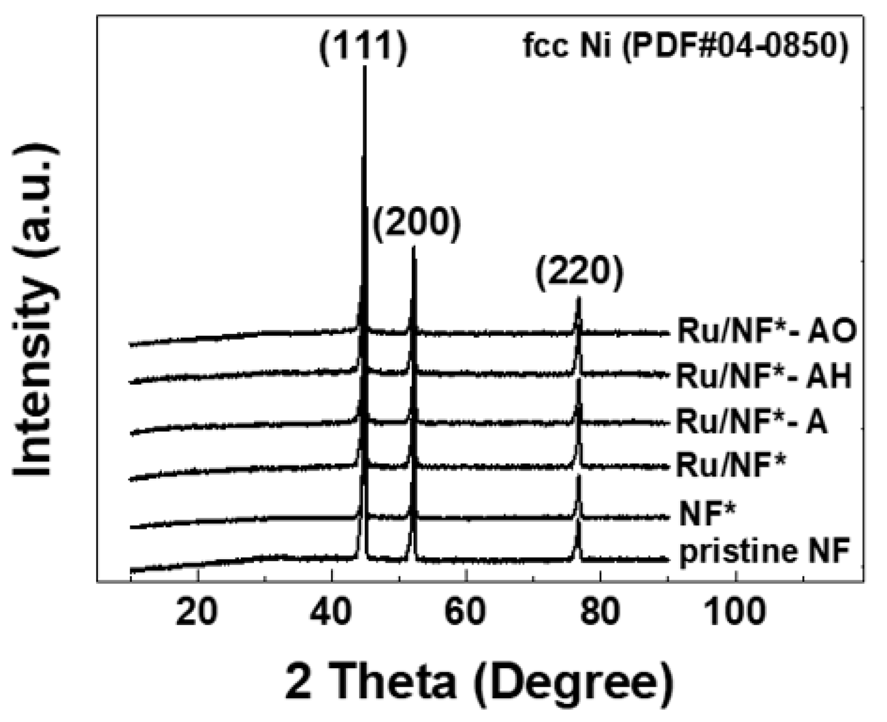
3.3. XRD
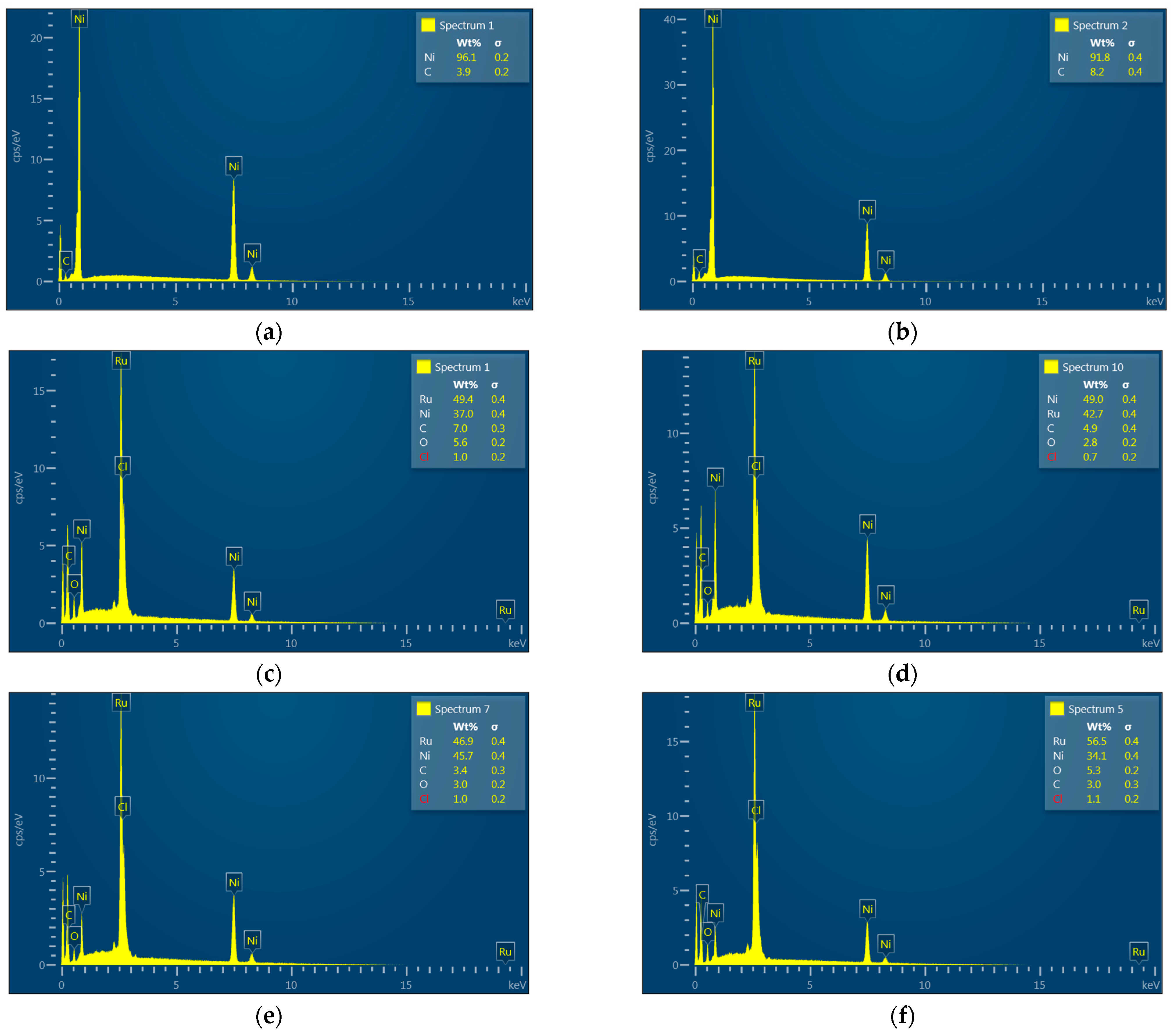
3.4. EDS and XPS
3.5. Evaluation of Electrocatalytic Activity
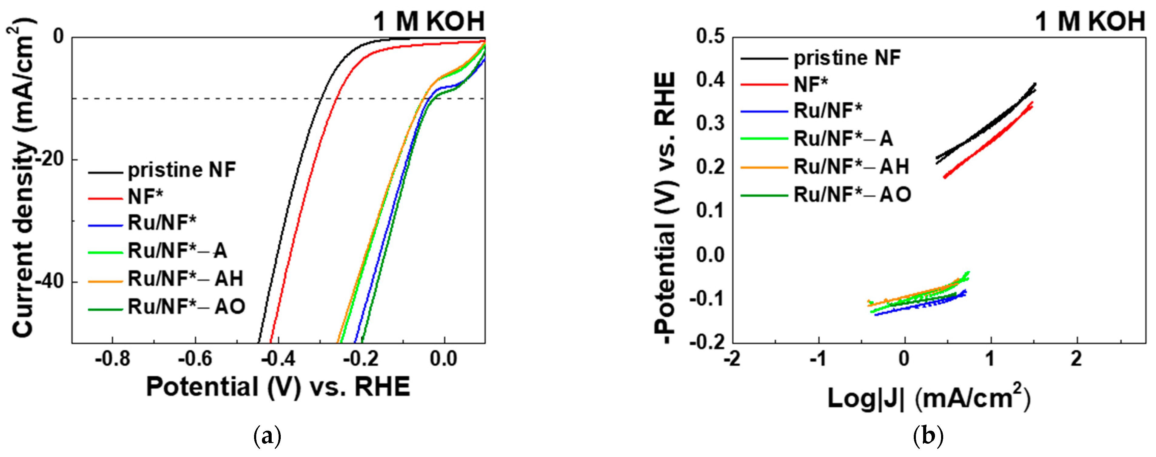
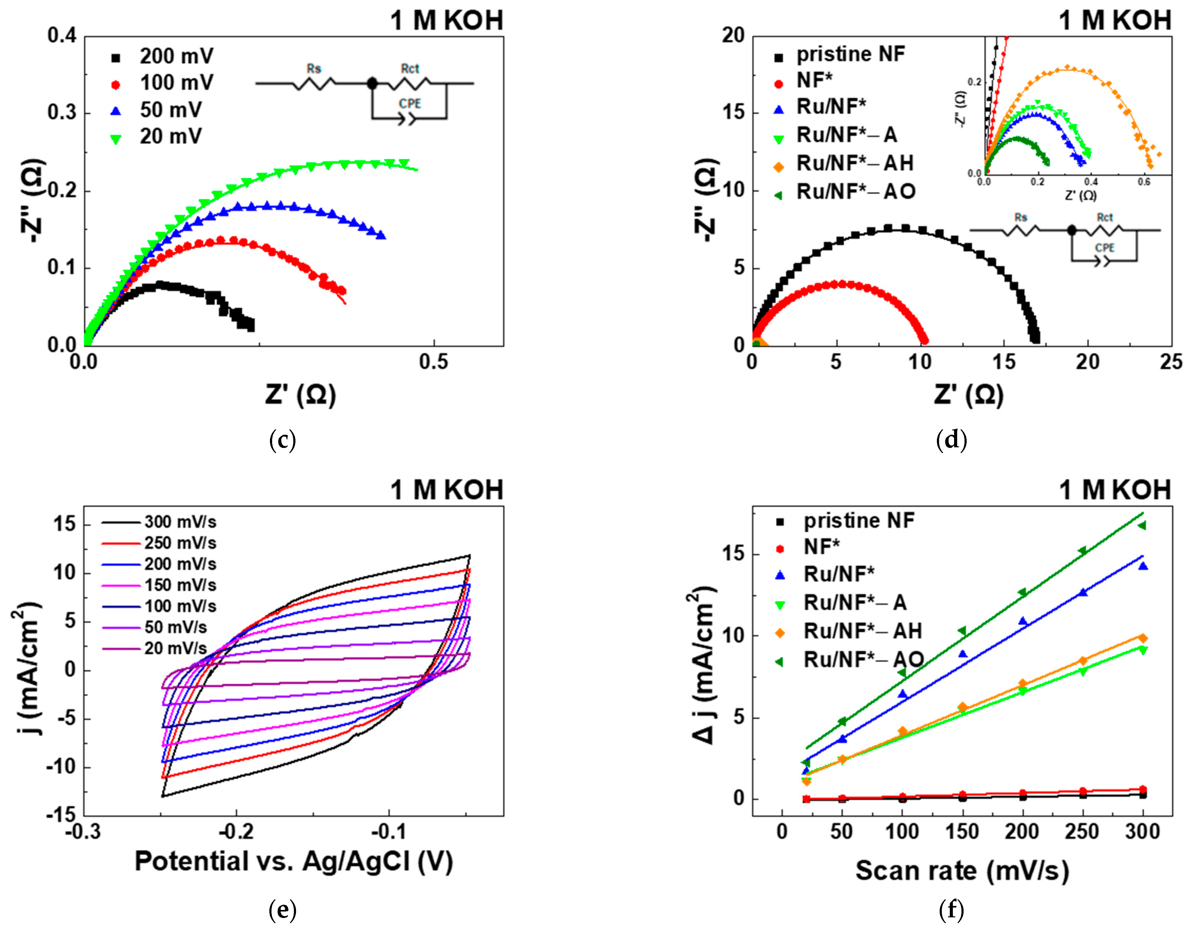
3.5.1. KOH Electrolyte
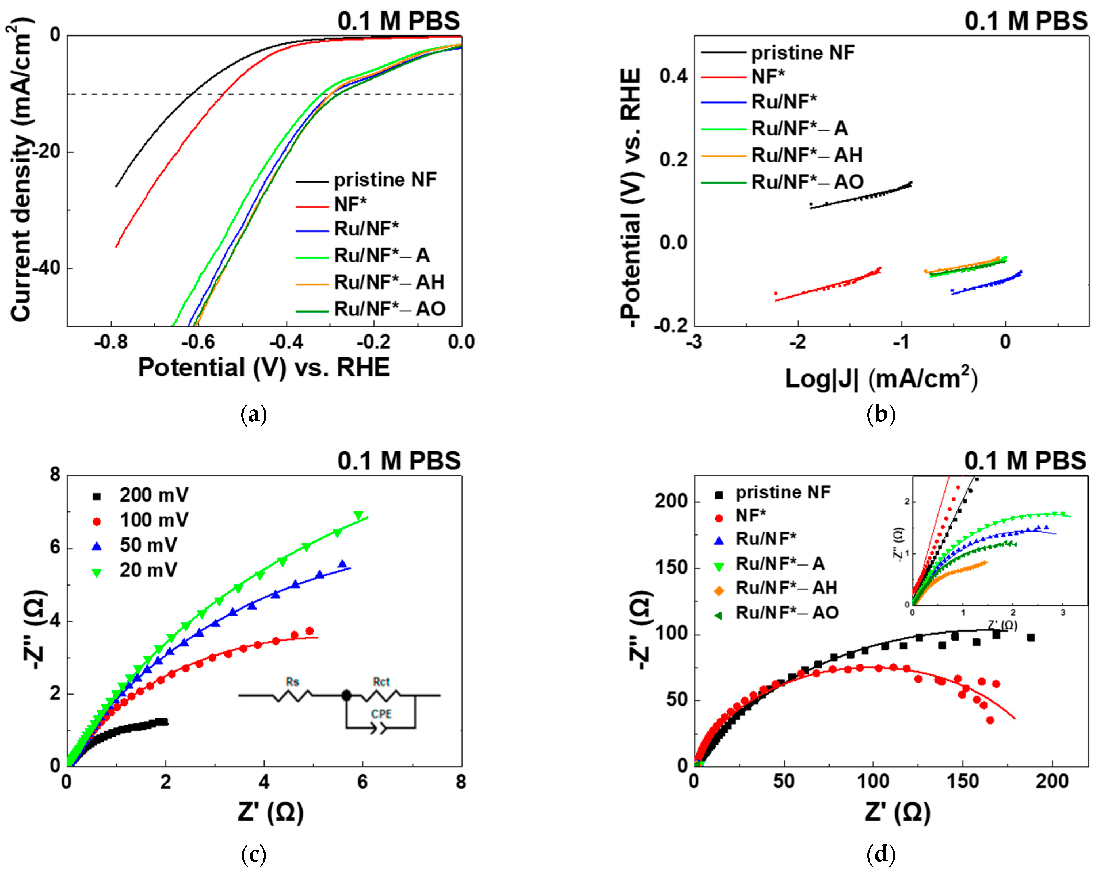
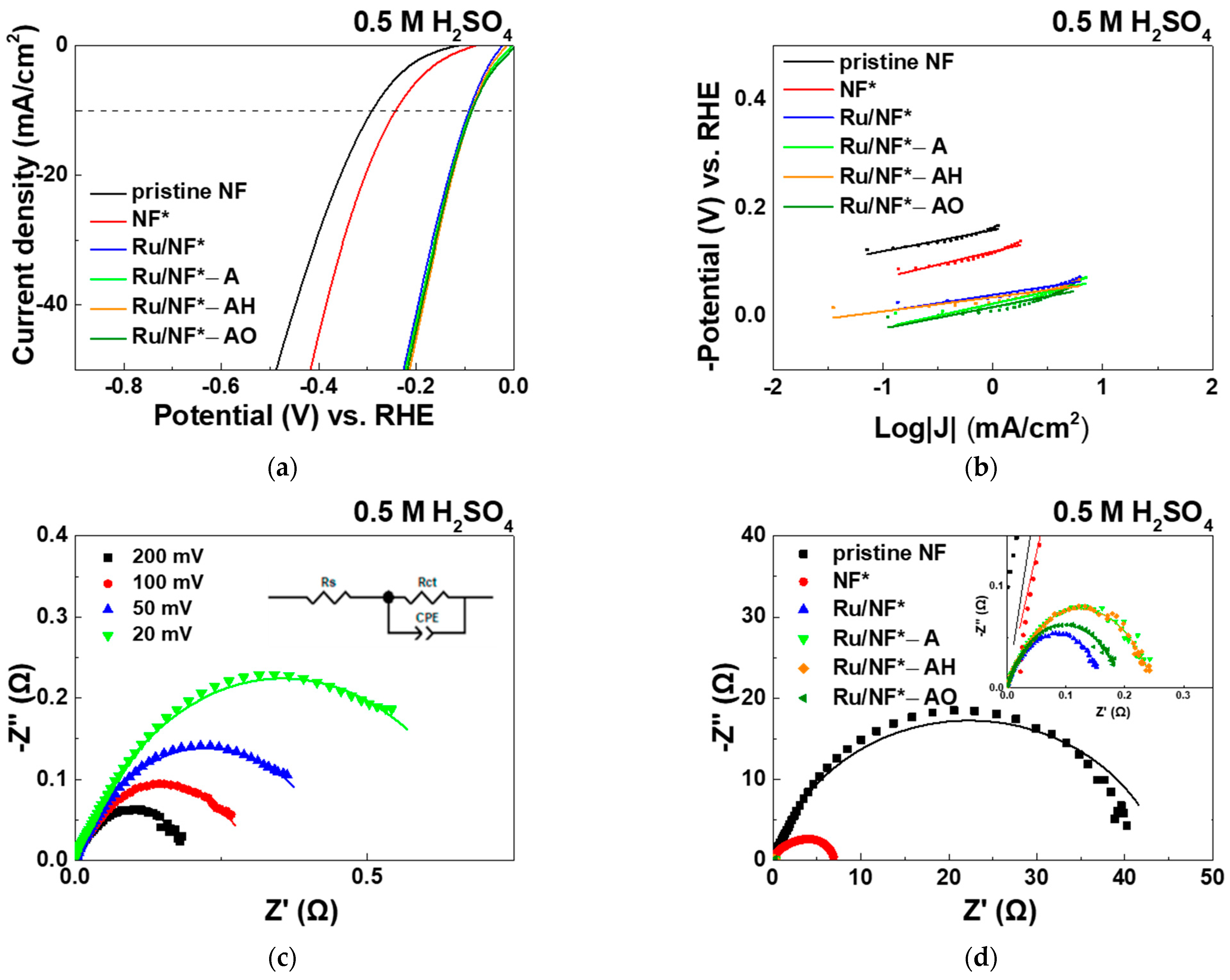
3.5.2. PBS and H2SO4 Electrolyte
4. Conclusions
Supplementary Materials
Author Contributions
Funding
Institutional Review Board Statement
Informed Consent Statement
Data Availability Statement
Conflicts of Interest
References
- van der Hoeven, M. World Energy Outlook 2012; International Energy Agency: Tokyo, Japan, 2013. [Google Scholar]
- OECD; IEA. Energy and Air Pollution: World Energy Outlook Special Report 2016; International Energy Agency: Paris, France, 2016. [Google Scholar]
- Shi, Y.; Zhang, B. Correction: Recent advances in transition metal phosphide nanomaterials: Synthesis and applications in hydrogen evolution reaction. Chem. Soc. Rev. 2016, 45, 1781. [Google Scholar] [CrossRef] [PubMed] [Green Version]
- Jiang, P.; Yang, Y.; Shi, R.; Xia, G.; Chen, J.; Su, J.; Chen, Q. Pt-like electrocatalytic behavior of Ru–MoO2 nanocomposites for the hydrogen evolution reaction. J. Mater. Chem. A 2017, 5, 5475–5485. [Google Scholar] [CrossRef]
- Xia, J.; Volokh, M.; Peng, G.; Fu, Y.; Wang, X.; Shalom, M. Low-cost porous ruthenium layer deposited on nickel foam as a highly active universal-pH electrocatalyst for the hydrogen evolution reaction. ChemSusChem 2019, 12, 2780–2787. [Google Scholar] [CrossRef] [PubMed]
- Wang, J.; Wei, Z.; Mao, S.; Li, H.; Wang, Y. Highly uniform Ru nanoparticles over N-doped carbon: pH and temperature-universal hydrogen release from water reduction. Energy Environ. Sci. 2018, 11, 800–806. [Google Scholar] [CrossRef]
- Li, Y.; Zhang, L.; Qin, Y.; Chu, F.; Kong, Y.; Tao, Y.; Li, Y.; Bu, Y.; Ding, D.; Liu, M. Crystallinity dependence of ruthenium nanocatalyst toward hydrogen evolution reaction. ACS Catal. 2018, 8, 5714–5720. [Google Scholar] [CrossRef]
- Zhang, C.; Jiang, L.; Zhang, Y.; Hu, J.; Leung, M.K. Janus effect of O2 plasma modification on the electrocatalytic hydrogen evolution reaction of MoS2. J. Catal. 2018, 361, 384–392. [Google Scholar] [CrossRef]
- Li, S.; Zhou, S.; Wang, X.; Tang, P.; Pasta, M.; Warner, J.H. Increasing the electrochemical activity of basal plane sites in porous 3D edge rich MoS2 thin films for the hydrogen evolution reaction. Mater. Today Energy 2019, 13, 134–144. [Google Scholar] [CrossRef]
- Tao, L.; Duan, X.; Wang, C.; Duan, X.; Wang, S. Plasma-engineered MoS 2 thin-film as an efficient electrocatalyst for hydrogen evolution reaction. Chem. Commun. 2015, 51, 7470–7473. [Google Scholar] [CrossRef]
- Zhang, T.; Wu, J.; Chen, J.; Pan, Q.; Wang, X.; Zhong, H.; Tao, R.; Yan, J.; Hu, Y.; Ye, X.; et al. Activating titanium metal with H2 plasma for the hydrogen evolution reaction. ACS Appl. Mater. Interfaces 2021, 13, 24682–24691. [Google Scholar] [CrossRef]
- Wang, C.; Jiang, J.; Ding, T.; Chen, G.; Xu, W.; Yang, Q. Monodisperse ternary NiCoP nanostructures as a bifunctional electrocatalyst for both hydrogen and oxygen evolution reactions with excellent performance. Adv. Mater. Interfaces 2016, 3, 1500454. [Google Scholar] [CrossRef]
- Jiang, N.; You, B.; Sheng, M.; Sun, Y. Electrodeposited cobalt-phosphorous-derived films as competent bifunctional catalysts for overall water splitting. Angew. Chem. 2015, 127, 6349–6352. [Google Scholar] [CrossRef] [Green Version]
- Zhu, Y.-P.; Liu, Y.-P.; Ren, T.-Z.; Yuan, Z.-Y. Self-supported cobalt phosphide mesoporous nanorod arrays: A flexible and bifunctional electrode for highly active electrocatalytic water reduction and oxidation. Adv. Funct. Mater. 2015, 25, 7337–7347. [Google Scholar] [CrossRef]
- Liu, B.; Zhang, L.; Xiong, W.; Ma, M. Cobalt-nanocrystal-assembled hollow nanoparticles for electrocatalytic hydrogen generation from neutral-pH water. Angew. Chem. 2016, 128, 6837–6841. [Google Scholar] [CrossRef]
- Harnisch, F.; Sievers, G.; Schröder, U. Tungsten carbide as electrocatalyst for the hydrogen evolution reaction in pH neutral electrolyte solutions. Appl. Catal. B Environ. 2009, 89, 455–458. [Google Scholar] [CrossRef]
- Popczun, E.J.; Read, C.G.; Roske, C.W.; Lewis, N.S.; Schaak, R.E. Highly active electrocatalysis of the hydrogen evolution reaction by cobalt phosphide nanoparticles. Angew. Chem. Int. Ed. 2014, 53, 5427–5430. [Google Scholar] [CrossRef] [PubMed]
- Jiang, P.; Liu, Q.; Liang, Y.; Tian, J.; Asiri, A.M.; Sun, X. A cost-effective 3D hydrogen evolution cathode with high catalytic activity: FeP nanowire array as the active phase. Angew. Chem. 2014, 126, 13069–13073. [Google Scholar] [CrossRef]
- Han, S.; Feng, Y.; Zhang, F.; Yang, C.; Yao, Z.; Zhao, W.; Qiu, F.; Yang, L.; Yao, Y.; Zhuang, X.; et al. Metal-phosphide-containing porous carbons derived from an ionic-polymer framework and applied as highly efficient electrochemical catalysts for water splitting. Adv. Funct. Mater. 2015, 25, 3899–3906. [Google Scholar] [CrossRef]
- Vrubel, H.; Hu, X. Molybdenum boride and carbide catalyze hydrogen evolution in both acidic and basic solutions. Angew. Chem. Int. Ed. 2012, 51, 12703–12706. [Google Scholar]
- Gao, M.-R.; Liang, J.-X.; Zheng, Y.-R.; Xu, Y.-F.; Jiang, J.; Gao, Q.; Li, J.; Yu, S.-H. An efficient molybdenum disulfide/cobalt diselenide hybrid catalyst for electrochemical hydrogen generation. Nat. Commun. 2015, 6, 5982. [Google Scholar] [CrossRef]
- Zhang, B.; Lui, Y.H.; Gaur, A.P.S.; Chen, B.; Tang, X.; Qi, Z.; Hu, S. Hierarchical FeNiP@Ultrathin Carbon Nanoflakes as Alkaline Oxygen Evolution and Acidic Hydrogen Evolution Catalyst for Efficient Water Electrolysis and Organic Decomposition. ACS Appl. Mater. Interfaces 2018, 10, 8739–8748. [Google Scholar] [CrossRef]
- Wang, D.-Y.; Gong, M.; Chou, H.-L.; Pan, C.-J.; Chen, H.-A.; Wu, Y.; Lin, M.-C.; Guan, M.; Yang, J.; Chen, C.-W.; et al. Highly active and stable hybrid catalyst of cobalt-doped fes2 nanosheets–carbon nanotubes for hydrogen evolution reaction. J. Am. Chem. Soc. 2015, 137, 1587–1592. [Google Scholar] [CrossRef] [PubMed]
- Chen, W.-F.; Sasaki, K.; Ma, C.; Frenkel, A.I.; Marinkovic, N.; Muckerman, J.T.; Zhu, Y.; Adzic, R.R. Hydrogen-evolution catalysts based on non-noble metal nickel–molybdenum nitride nanosheets. Angew. Chem. Int. Ed. 2012, 51, 6131–6135. [Google Scholar] [CrossRef] [PubMed]
- Mahmood, N.; Yao, Y.; Zhang, J.-W.; Pan, L.; Zhang, X.; Zou, J.-J. Electrocatalysts for Hydrogen evolution in alkaline electrolytes: Mechanisms, challenges, and prospective solutions. Adv. Sci. 2018, 5, 1700464. [Google Scholar] [CrossRef] [PubMed]
- Tian, J.; Liu, Q.; Asiri, A.M.; Sun, X. Self-supported nanoporous cobalt phosphide nanowire arrays: An efficient 3D hydrogen-evolving cathode over the wide range of pH 0–14. J. Am. Chem. Soc. 2014, 136, 7587–7590. [Google Scholar] [CrossRef]
- Ye, R.; Liu, Y.; Peng, Z.; Wang, T.; Jalilov, A.S.; Yakobson, B.I.; Wei, S.-H.; Tour, J.M. High performance electrocatalytic reaction of hydrogen and oxygen on ruthenium nanoclusters. ACS Appl. Mater. Interfaces 2017, 9, 3785–3791. [Google Scholar] [CrossRef] [Green Version]
- Ledezma-Yanez, I.; Wallace, W.D.Z.; Sebastián-Pascual, P.; Climent, V.; Feliu, J.M.; Koper, M.T.M. Interfacial water reorganization as a pH-dependent descriptor of the hydrogen evolution rate on platinum electrodes. Nat. Energy 2017, 2, 17031. [Google Scholar] [CrossRef] [Green Version]
- Huang, L.; Hou, Y.; Yu, Z.; Peng, Z.; Wang, L.; Huang, J.; Zhang, B.; Qian, L.; Wu, L.; Li, Z. Pt/Fe-NF electrode with high double-layer capacitance for efficient hydrogen evolution reaction in alkaline media. Int. J. Hydrogen Energy 2017, 42, 9458–9466. [Google Scholar] [CrossRef]
- Lotfi, N.; Shahrabi, T.; Darband, G.B. Electrodeposition of cedar leaf-like graphene Oxide@Ni–Cu@Ni foam electrode as a highly efficient and ultra-stable catalyst for hydrogen evolution reaction. Electrochim. Acta 2019, 326, 134949. [Google Scholar] [CrossRef]
- Chen, D.; Liu, Z. Dual-axial gradient doping (Zr and Sn) on hematite for promoting charge separation in photoelectrochemical water splitting. ChemSusChem 2018, 11, 3438–3448. [Google Scholar] [CrossRef]
- Tseng, C.-H.; Hsin, J.-C.; Tsai, J.-H.; Chen, J.-Z. Dielectric-barrier-discharge jet treated flexible supercapacitors with carbon cloth current collectors of long-lasting hydrophilicity. J. Electrochem. Soc. 2020, 167, 116511. [Google Scholar] [CrossRef]
- Xia, J.; He, G.; Zhang, L.; Sun, X.; Wang, X. Hydrogenation of nitrophenols catalyzed by carbon black-supported nickel nanoparticles under mild conditions. Appl. Catal. B Environ. 2016, 180, 408–415. [Google Scholar] [CrossRef]
- Demir, E.; Akbayrak, S.; Önal, A.M.; Özkar, S. Nanoceria-supported ruthenium(0) nanoparticles: Highly active and stable catalysts for hydrogen evolution from water. ACS Appl. Mater. Interfaces 2018, 10, 6299–6308. [Google Scholar] [CrossRef] [PubMed]
- Safizadeh, F.; Ghali, E.; Houlachi, G. Electrocatalysis developments for hydrogen evolution reaction in alkaline solutions—A review. Int. J. Hydrogen Energy 2015, 40, 256–274. [Google Scholar] [CrossRef]
- Choquette, Y.; Brossard, L.; Lasia, A.; Menard, H. Study of the kinetics of hydrogen evolution reaction on Raney Nickel composite-coated electrode by AC impedance technique. J. Electrochem. Soc. 1990, 137, 1723–1730. [Google Scholar] [CrossRef]
- Lasia, A.; Rami, A. Kinetics of hydrogen evolution on nickel electrodes. J. Electroanal. Chem. Interfacial Electrochem. 1990, 294, 123–141. [Google Scholar] [CrossRef]
- Zhang, R.; Wang, X.; Yu, S.; Wen, T.; Zhu, X.; Yang, F.; Sun, X.; Wang, X.; Hu, W. Ternary NiCo2Px nanowires as pH-universal electrocatalysts for highly efficient hydrogen evolution reaction. Adv. Mater. 2017, 29, 1605502. [Google Scholar] [CrossRef]
- Gao, K.; Wang, Y.; Wang, Z.; Zhu, Z.; Wang, J.; Luo, Z.; Zhang, C.; Huang, X.; Zhang, H.; Huang, W. Ru nanodendrites composed of ultrathin fcc/hcp nanoblades for the hydrogen evolution reaction in alkaline solutions. Chem. Commun. 2018, 54, 4613–4616. [Google Scholar] [CrossRef]
- Herraiz-Cardona, I.; Ortega, E.; Antón, J.G.; Pérez-Herranz, V. Assessment of the roughness factor effect and the intrinsic catalytic activity for hydrogen evolution reaction on Ni-based electrodeposits. Int. J. Hydrogen Energy 2011, 36, 9428–9438. [Google Scholar] [CrossRef]
- Huang, Y.; Ge, J.; Hu, J.; Zhang, J.; Hao, J.; Wei, Y. Nitrogen-doped porous molybdenum carbide and phosphide hybrids on a carbon matrix as highly effective electrocatalysts for the hydrogen evolution reaction. Adv. Energy Mater. 2018, 8, 1701601. [Google Scholar] [CrossRef]
- Sun, F.; Wang, G.; Ding, Y.; Wang, C.; Yuan, B.; Lin, Y. NiFe-based metal–Organic framework nanosheets directly supported on nickel foam acting as robust electrodes for electrochemical oxygen evolution reaction. Adv. Energy Mater. 2018, 8, 1800584. [Google Scholar] [CrossRef]
- Raja, S.D.; Lin, H.-W.; Lu, S.-Y. Synergistically well-mixed MOFs grown on nickel foam as highly efficient durable bifunctional electrocatalysts for overall water splitting at high current densities. Nano Energy 2019, 57, 1800584. [Google Scholar]
- Cai, W.; Chen, R.; Yang, H.; Tao, H.B.; Wang, H.-Y.; Gao, J.; Liu, W.; Liu, S.; Hung, S.-F.; Liu, B. Amorphous versus crystalline in water oxidation catalysis: A case study of NiFe alloy. Nano Lett. 2020, 20, 4278–4285. [Google Scholar] [CrossRef] [PubMed]
- Zhang, Y.; Ouyang, B.; Xu, J.; Chen, S.; Rawat, R.S.; Fan, H.J. 3D porous hierarchical nickel–Molybdenum nitrides synthesized by RF plasma as highly active and stable hydrogen-evolution-reaction electrocatalysts. Adv. Energy Mater. 2016, 6, 1600221. [Google Scholar] [CrossRef]
- Wu, H.B.; Xia, B.Y.; Yu, L.; Yu, X.-Y.; Lou, X.W. Porous molybdenum carbide nano-octahedrons synthesized via confined carburization in metal-organic frameworks for efficient hydrogen production. Nat. Commun. 2015, 6, 6512. [Google Scholar] [CrossRef] [PubMed]
- Lu, Z.; Zhu, W.; Yu, X.; Zhang, H.; Li, Y.; Sun, X.; Wang, X.; Wang, H.; Wang, J.; Luo, J.; et al. Ultrahigh hydrogen evolution performance of under-water “superaerophobic” MoS2 nanostructured electrodes. Adv. Mater. 2014, 26, 2683–2687. [Google Scholar] [CrossRef]
- Li, Y.; Zhou, W.; Zhao, X.; Cheng, W.; Su, H.; Zhang, H.; Liu, M.; Liu, Q. Donutlike RuCu nanoalloy with ultrahigh mass activity for efficient and robust oxygen evolution in acid solution. ACS Appl. Energy Mater. 2019, 2, 7483–7489. [Google Scholar] [CrossRef]
- Li, Y.; He, J.; Cheng, W.; Su, H.; Li, C.; Zhang, H.; Liu, M.; Zhou, W.; Chen, X.; Liu, Q. High mass-specific reactivity of a defect-enriched Ru electrocatalyst for hydrogen evolution in harsh alkaline and acidic media. Sci. China Mater. 2021, 64, 2467–2476. [Google Scholar] [CrossRef]
- Zhang, Y.; Lei, H.; Duan, D.; Villota, E.; Liu, C.; Ruan, R. New insight into the mechanism of the hydrogen evolution reaction on MoP(001) from first principles. ACS Appl. Mater. Interfaces 2018, 10, 20429–20439. [Google Scholar] [CrossRef]
- Yan, Y.; Xia, B.Y.; Zhao, B.; Wang, X. A review on noble-metal-free bifunctional heterogeneous catalysts for overall electrochemical water splitting. J. Mater. Chem. A 2016, 4, 17587–17603. [Google Scholar] [CrossRef] [Green Version]

| Element (wt.%) | |||||
|---|---|---|---|---|---|
| Ni | Ru | O | C | Cl | |
| Pristine NF | 96.1 | - | 3.9 | - | - |
| NF* | 91.8 | - | 8.2 | - | - |
| Ru/NF* | 37.0 | 49.4 | 5.6 | 7.0 | 1.0 |
| Ru/NF*-A | 49.0 | 42.7 | 2.8 | 4.9 | 0.7 |
| Ru/NF*-AH | 45.7 | 46.9 | 3.0 | 3.4 | 1.0 |
| Ru/NF*-AO | 34.3 | 56.5 | 5.3 | 3.0 | 1.1 |
| Electrocatalyst | Overpotential (mV) @Current Density 10 mA/cm2 | Tafel Slope (mV/dec) | Rct (Ω) | 2CdL (mF/cm2) |
|---|---|---|---|---|
| Pristine NF | 299 | 147 | 17.1 | 1.12 |
| NF* | 260 | 161 | 10.3 | 2.19 |
| Ru/NF* | 36 | 44 | 0.4 | 44.60 |
| Ru/NF*-A | 50 | 68 | 0.4 | 27.85 |
| Ru/NF*-AH | 50 | 49 | 0.6 | 30.61 |
| Ru/NF*-AO | 25 | 33 | 0.2 | 51.41 |
| Electrocatalyst | Overpotential (mV) @ Current Density 10 mA/cm2 | Tafel Slope (mV/dec) | Rct (Ω) |
|---|---|---|---|
| pristine NF | 617 | 56 | 327.2 |
| NF* | 544 | 68 | 197.2 |
| Ru/NF* | 300 | 69 | 4.6 |
| Ru/NF*-A | 320 | 55 | 5.3 |
| Ru/NF*-AH | 300 | 45 | 3.5 |
| Ru/NF*-AO | 281 | 45 | 3.9 |
| Electrocatalyst | Overpotential (mV) @ Current Density 10 mA/cm2 | Tafel Slope (mV/dec) | Rct (Ω) |
|---|---|---|---|
| pristine NF | 291 | 39 | 44.6 |
| NF* | 243 | 49 | 7.3 |
| Ru/NF* | 94 | 31 | 0.2 |
| Ru/NF*-A | 89 | 23 | 0.3 |
| Ru/NF*-AH | 87 | 35 | 0.3 |
| Ru/NF*-AO | 86 | 26 | 0.2 |
Publisher’s Note: MDPI stays neutral with regard to jurisdictional claims in published maps and institutional affiliations. |
© 2022 by the authors. Licensee MDPI, Basel, Switzerland. This article is an open access article distributed under the terms and conditions of the Creative Commons Attribution (CC BY) license (https://creativecommons.org/licenses/by/4.0/).
Share and Cite
Liu, C.; Tseng, C.-Y.; Wang, Y.-C.; Cheng, I.-C.; Chen, J.-Z. Low-Pressure Plasma-Processed Ruthenium/Nickel Foam Electrocatalysts for Hydrogen Evolution Reaction. Materials 2022, 15, 2603. https://doi.org/10.3390/ma15072603
Liu C, Tseng C-Y, Wang Y-C, Cheng I-C, Chen J-Z. Low-Pressure Plasma-Processed Ruthenium/Nickel Foam Electrocatalysts for Hydrogen Evolution Reaction. Materials. 2022; 15(7):2603. https://doi.org/10.3390/ma15072603
Chicago/Turabian StyleLiu, Chen, Chia-Yun Tseng, Ying-Chyi Wang, I-Chun Cheng, and Jian-Zhang Chen. 2022. "Low-Pressure Plasma-Processed Ruthenium/Nickel Foam Electrocatalysts for Hydrogen Evolution Reaction" Materials 15, no. 7: 2603. https://doi.org/10.3390/ma15072603
APA StyleLiu, C., Tseng, C.-Y., Wang, Y.-C., Cheng, I.-C., & Chen, J.-Z. (2022). Low-Pressure Plasma-Processed Ruthenium/Nickel Foam Electrocatalysts for Hydrogen Evolution Reaction. Materials, 15(7), 2603. https://doi.org/10.3390/ma15072603