
The Effect of Roughness in Absorbing Materials on Solar Air Heater Performance


 , ,
, ,  and
and 
Abstract
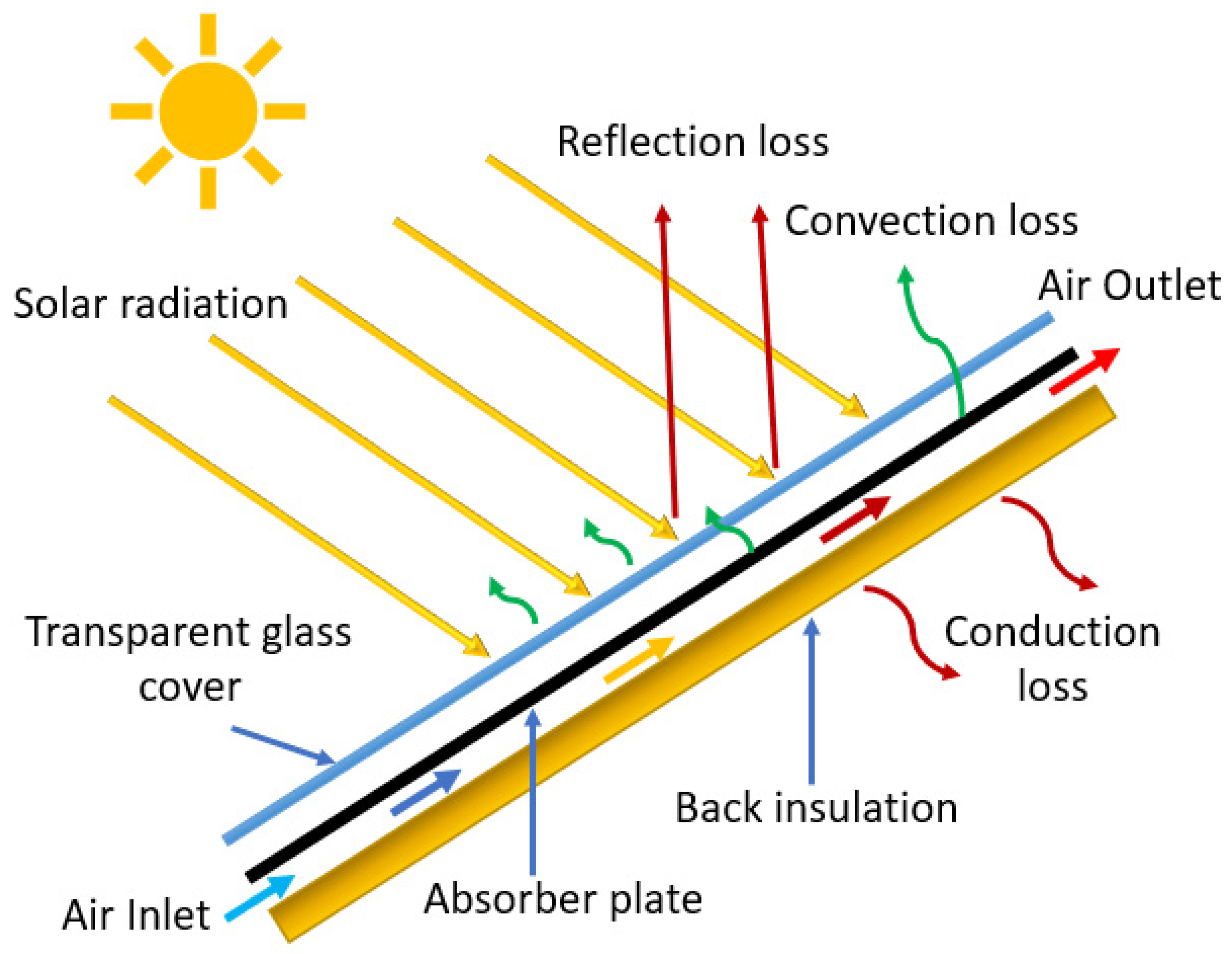
:1. Introduction
2. Thermal and Effective Performance Assessment Approach of Roughened SAH
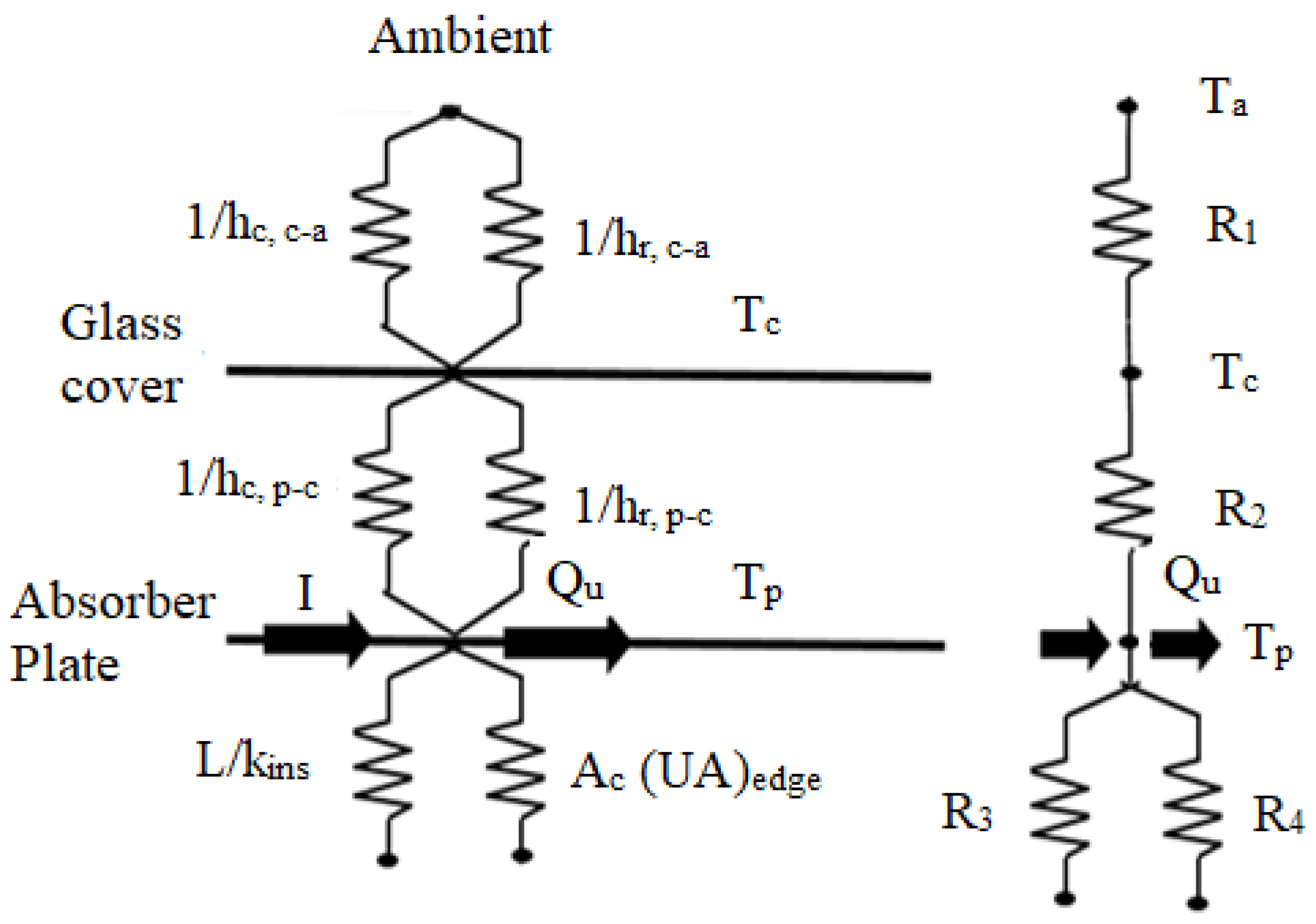
3. Mathematical Model for Calculation of Thermo-Hydraulic Performance of SAH
4. Discussion
5. Conclusions
- (a)
- The shape, size, and arrangement of artificial roughness on the duct surface are the most important factors for the performance optimization of SAH.
- (b)
- The broken-arc shaped ribs, combined with staggered-arc rib pieces have better performance over the broken arc shape and arc shape rib roughness.
- (c)
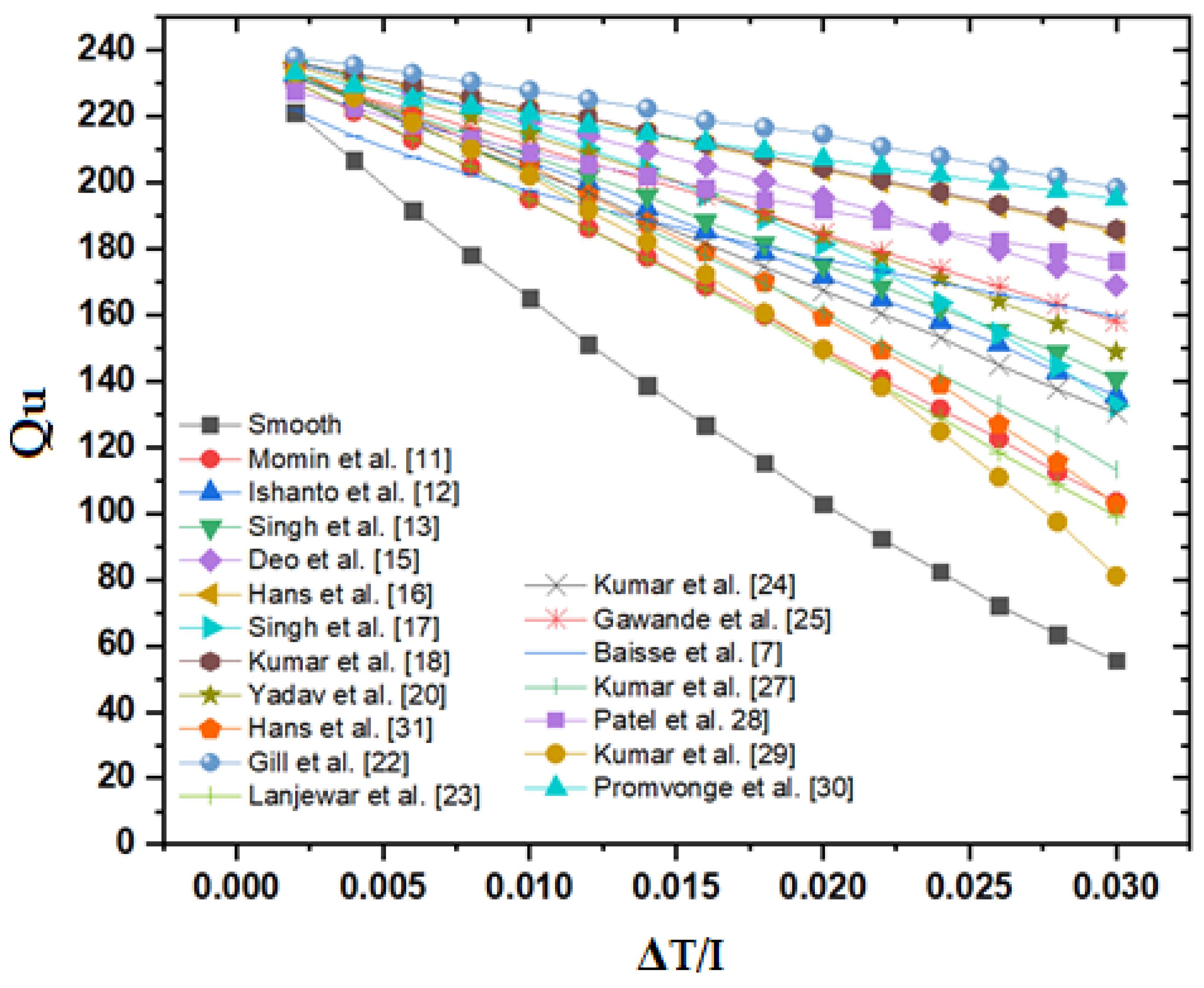
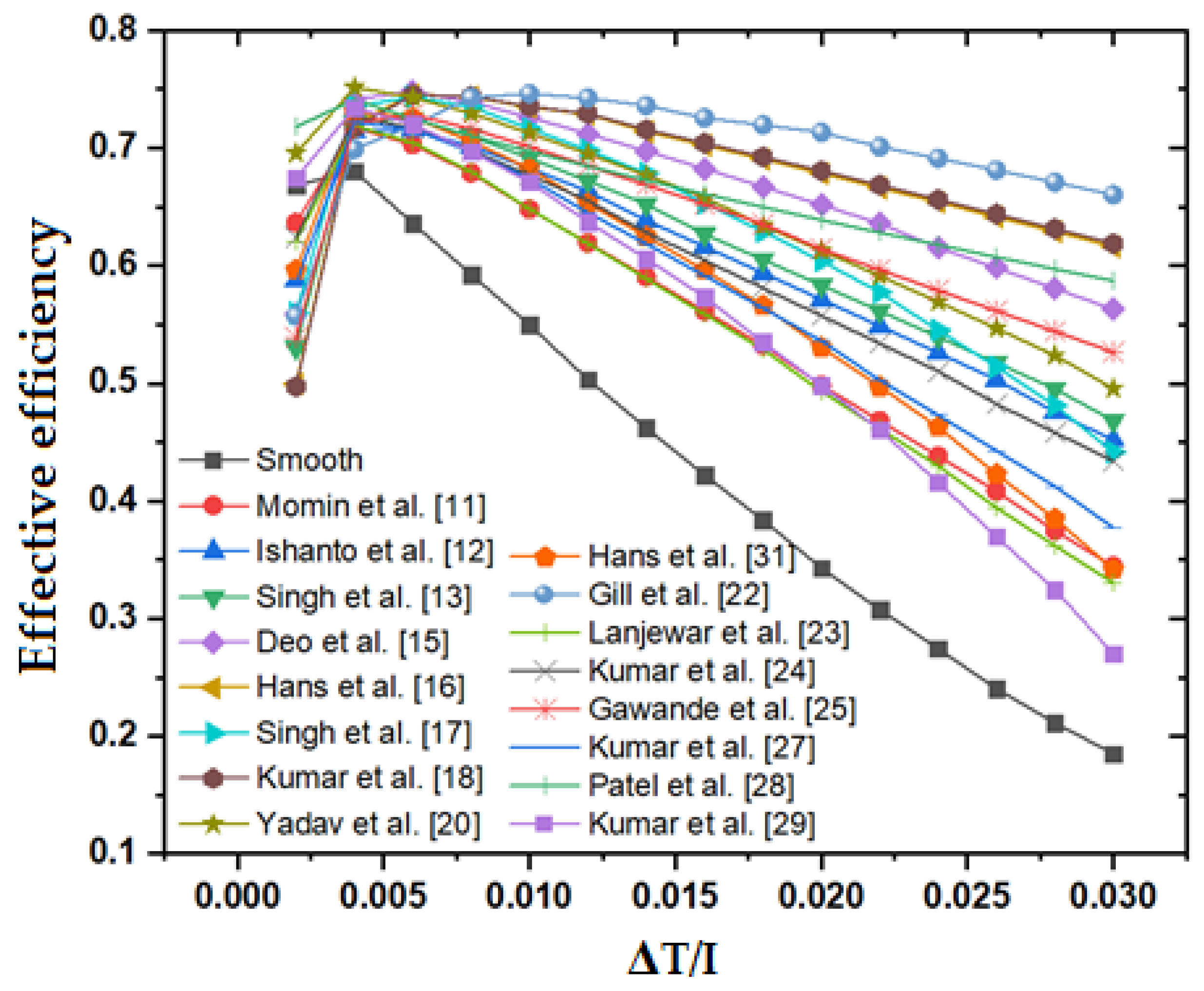
- The thermal and effective efficiency strongly depends on the roughness parameter, Re, and ΔT/I.
- (d)
- For most of the rib roughness geometries, optimum performance has been achieved at the following parameters; p/e = 10, W/w = 6, e/Dh = 0.043 and α = 60°.
- (e)
- The highest value of effective efficiency is achieved by all distinct roughnesses in the ΔT/I range of 0.0015 to 0.0100.
- (f)
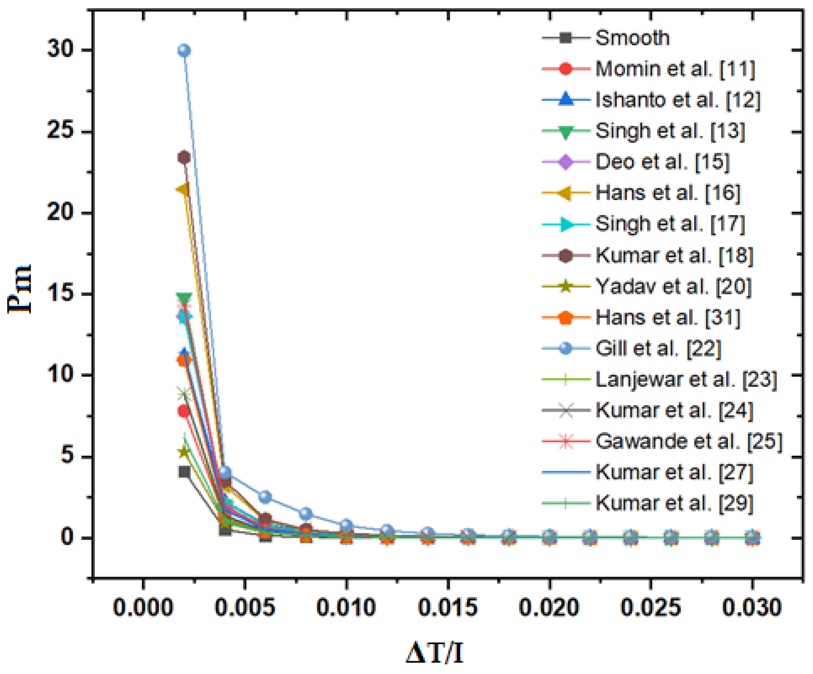
- The twisted rib shows a lower value of effective efficiency at a higher value of ΔT/I.
- (g)
- The unique combination of parameters p/e = 10, e/dh = 0.043 and α = 60° are observed for the best performance at ΔT/I > 0.00789 K·m2/W.
- (h)
- The staggered broken arc hybrid-rib roughness consistently shows a higher thermal efficiency among all other distinct roughness geometries for the ascending values of ΔT/I.
- (i)
- The staggered broken arc hybrid-rib roughness shows higher effective efficiency over the other roughnesses. This roughness shows a value of effective efficiency equal to 74.63% at ΔT/I equal to 0.01.
- (j)
- The staggered broken arc hybrid-rib roughness consistently shows higher values of TEIF among all other distinct roughness geometries for the ascending values of ΔT/I.
Author Contributions
Funding
Institutional Review Board Statement
Informed Consent Statement
Data Availability Statement
Conflicts of Interest
Nomenclature
| Symbol | Title | Unit |
| b | Roughness width | m |
| c | Characteristic separation length | m |
| d′ | Diameter of dimples | m |
| d/x | Relative gap position | - |
| dR | Relative punched hole size | - |
| D | Pipe inside diameter (to base of ribs) | m |
| De | Equivalent diameter of annulus (d1-d2) | m |
| Dh | Hydraulic diameter of duct | m |
| e | Roughness height | m |
| e+ | Roughness Reynolds number | - |
| e/Dh | Relative roughness height | - |
| e/H | Blockage ratio | - |
| fs | Friction factor of smooth surface | - |
| f | Friction factor of roughened surface | - |
| FR | Heat removal factor | - |
| g | Heat transfer roughness function | - |
| hr | Radiative heat transfer coeff. | W/m2·K |
| hc | Convective heat transfer coeff. | W/m2·K |
| hw | Wind convective heat transfer coeff. | W/m2·K |
| I | Insolation | W/m2 |
| L | Length of test section | m |
| Nu | Nusselt number | - |
| Ng | Number of gaps on half arc | - |
| p/g | Relative pitch to gap ratio | - |
| p/H | Rib pitch to channel height ratio | - |
| p′/p | Relative staggered rib pitch | - |
| Pt/b | Relative longitudinal length of obstacles | - |
| Pt/e | Relative transversal length of obstacles | - |
| Pr | Prandtl number | - |
| PR | Relative winglet pitch | - |
| Qu | Heat gain | W |
| Qe+ | Heat transfer function | - |
| r/e | Relative staggered rib size | - |
| R | Momentum transfer roughness function | - |
| Ra | Rayleigh number | - |
| Re | Reynolds number | - |
| S | Short way length between dimples | m |
| s′/s | Relative gap position | - |
| St | Stanton number | - |
| Ta | Ambient temperature | K |
| Tf | Mean air temperature | K |
| Ti | Air inlet temperature | K |
| Tp | Plate temperature | K |
| Tw | Wall temperature | K |
| ΔP | Pressure drops | N/m2 |
| UO | Overall heat loss coefficient | W/m2·K |
| V | Velocity of air in SAH duct | m/s |
| w/e | Staggered rib length to rib height | - |
| W/e | Width to height ratio | - |
| W/H | Width to duct height ratio | - |
| W1/w | Relative gap position | - |
| W/w | Relative roughness width | - |
| ti | Thickness of insulation | mm |
| tg | Thickness of glass cover | mm |
| tg | Height of collector edge | mm |
| Ub | Back heat loss coefficient | W/m2·K |
| Ue | Edge heat loss coefficient | W/m2·K |
| Ut | Top heat loss coefficient | W/m2·K |
| V | Air velocity | m/s |
| Vw | Wind Speed | m/s |
| α | Angle of attack | degree |
| α′ | Arc angle | degree |
| α/90 | Relative arc angle | - |
| φ | Chamfering angle of rib | degree |
| Β | Slope | degree |
| β′ | Thermal expansion coefficient of air | 1/K |
| εg | Glass cover emissivity | |
| εp | Absorber plate emissivity | |
| υ | Kinematic viscosity, | m2/s |
| τ | Transmissivity | |
| σ | Steafan-Boltzmann constant, | W/m2·K4 |
| η | Thermal efficiency | - |
References
- Singh, I.; Singh, S. A review of artificial roughness geometries employed in solar air heaters. Renew. Sustain. Energy Rev. 2018, 92, 405–425. [Google Scholar] [CrossRef]
- Alam, T.; Kim, M.-H. A critical review on artificial roughness provided in rectangular solar air heater duct. Renew. Sustain. Energy Rev. 2017, 69, 387–400. [Google Scholar] [CrossRef]
- Alam, T.; Kim, M.-H. Performance improvement of double-pass solar air heater—A state of art of review. Renew. Sustain. Energy Rev. 2017, 79, 779–793. [Google Scholar] [CrossRef]
- Alam, T.; Kim, M.-H. A comprehensive review on single phase heat transfer enhancement techniques in heat exchanger applications. Renew. Sustain. Energy Rev. 2018, 81, 813–839. [Google Scholar] [CrossRef]
- Singh Bisht, V.; Kumar Patil, A.; Gupta, A. Review and performance evaluation of roughened solar air heaters. Renew. Sustain. Energy Rev. 2018, 81, 954–977. [Google Scholar] [CrossRef]
- Alam, T.; Saini, R.P.; Saini, J.S. Use of turbulators for heat transfer augmentation in an air duct—A review. Renew. Energy 2014, 62, 689–715. [Google Scholar] [CrossRef]
- Baissi, M.T.; Brima, A.; Aoues, K.; Khanniche, R.; Moummi, N. Thermal behavior in a solar air heater channel roughened with delta-shaped vortex generators. Appl. Therm. Eng. 2019, 14, 113563. [Google Scholar] [CrossRef]
- Xiao, H.; Dong, Z.; Liu, Z.; Liu, W. Heat transfer performance and flow characteristics of solar air heaters with inclined trapezoidal vortex generators. Appl. Therm. Eng. 2020, 179, 115484. [Google Scholar] [CrossRef]
- Dong, Z.; Liu, P.; Xiao, H.; Liu, Z.; Liu, W. A study on heat transfer enhancement for solar air heaters with ripple surface. Renew. Energy 2021, 172, 477–487. [Google Scholar] [CrossRef]
- Jouybari, N.F.; Lundström, T.S. Performance improvement of a solar air heater by covering the absorber plate with a thin porous material. Energy 2020, 190, 116437. [Google Scholar] [CrossRef]
- Ebrahim-Momin, A.M.; Saini, J.S.; Solanki, S.C. Heat transfer and friction in solar air heater duct with V-shaped rib roughness on absorber plate. Int. J. Heat Mass Transf. 2002, 45, 3383–3396. [Google Scholar] [CrossRef]
- Istanto, T.; Danardono, D.; Yaningsih, I.; Wijayanta, A.T. Experimental study of heat transfer enhancement in solar air heater with different angle of attack of V-down continuous ribs. AIP Conf. Proc. 2016, 1737, 060002. [Google Scholar] [CrossRef]
- Singh, S.; Chander, S.; Saini, J.S. Heat transfer and friction factor correlations of solar air heater ducts artificially roughened with discrete V-down ribs. Energy 2011, 36, 5053–5064. [Google Scholar] [CrossRef]
- Singh, S.; Chander, S.; Saini, J.S. Thermal and effective efficiency-based analysis of discrete V-down rib-roughened solar air heaters. J. Renew. Sustain. Energy 2011, 3, 23107. [Google Scholar] [CrossRef]
- Deo, N.S.; Chander, S.; Saini, J.S. Performance analysis of solar air heater duct roughened with multigap V-down ribs combined with staggered ribs. Renew. Energy 2016, 91, 484–500. [Google Scholar] [CrossRef]
- Hans, V.S.; Saini, R.P.; Saini, J.S. Heat transfer and friction factor correlations for a solar air heater duct roughened artificially with multiple v-ribs. Sol. Energy 2010, 84, 898–911. [Google Scholar] [CrossRef]
- Singh, A.; Kumar, R.; Singh, P.; Goel, V. Solar air heater having multiple V-ribs with Multiple-Symmetric gaps as roughness elements on Absorber-Plate, A parametric study. Sustain. Energy Technol. Assess. 2021, 48, 101559. [Google Scholar] [CrossRef]
- Kumar, A.; Saini, R.P.; Saini, J.S. Experimental Investigations on Thermo-hydraulic Performance due to Flow- Attack- Angle in Multiple V-ribs with Gap in a Rectangular Duct of Solar Air Heaters. J. Sustain. Energy Environ. 2013, 4, 1–7. [Google Scholar]
- Kumar, A.; Saini, R.P.; Saini, J.S. Development of correlations for Nusselt number and friction factor for solar air heater with roughened duct having multi v-shaped with gap rib as arti fi cial roughness. Renew. Energy 2013, 58, 151–163. [Google Scholar] [CrossRef]
- Yadav, S.; Kaushal, M.; Varun; Siddhartha. Nusselt number and friction factor correlations for solar air heater duct having protrusions as roughness elements on absorber plate. Exp. Therm. Fluid. Sci. 2013, 44, 34–41. [Google Scholar] [CrossRef]
- Gill, R.S.; Hans, V.S.; Singh, S. Investigations on thermo-hydraulic performance of broken arc rib in a rectangular duct of solar air heater. Int. Commun. Heat Mass Transf. 2017, 88, 20–27. [Google Scholar] [CrossRef]
- Gill, R.S.; Hans, V.S.; Singh, R.P. Optimization of artificial roughness parameters in a solar air heater duct roughened with hybrid ribs. Appl. Therm. Eng. 2021, 191, 116871. [Google Scholar] [CrossRef]
- Lanjewar, A.M.; Bhagoria, J.L.; Sarviya, R.M.; Lanjewar, A.M.; Bhagoria, L. Performance analysis of W-shaped rib roughened solar air heater. J. Renew. Sustain. Energy 2011, 3, 043110. [Google Scholar] [CrossRef]
- Kumar, A.; Bhagoria, J.L.; Sarviya, R.M. Heat transfer and friction correlations for artificially roughened solar air heater duct with discrete W-shaped ribs. Energy Convers. Manag. 2009, 50, 2106–2117. [Google Scholar] [CrossRef]
- Gawande, V.B.; Dhoble, A.S.; Zodpe, D.B.; Chamoli, S. Experimental and CFD investigation of convection heat transfer in solar air heater with reverse L-shaped ribs. Sol. Energy 2016, 131, 275–295. [Google Scholar] [CrossRef]
- Kumar, A.; Layek, A. Nusselt number and friction characteristics of a solar air heater that has a winglet type vortex generator in the absorber surface. Int. Commun. Heat Mass Transf. 2012, 39, 634–639. [Google Scholar] [CrossRef]
- Kumar, A.; Layek, A. Nusselt number and friction factor correlation of solar air heater having winglet type vortex generator over absorber plate. Sol. Energy 2020, 205, 334–348. [Google Scholar] [CrossRef]
- Patel, Y.M.; Jain, S.V.; Lakhera, V.J. Thermo-hydraulic performance analysis of a solar air heater roughened with reverse NACA profile ribs. Appl. Therm. Eng. 2020, 170, 114940. [Google Scholar] [CrossRef]
- Kumar, A.; Layek, A. Energetic and exergetic performance evaluation of solar air heater with twisted rib roughness on absorber plate. J. Clean. Prod. 2019, 232, 617–628. [Google Scholar] [CrossRef]
- Promvonge, P.; Khanoknaiyakarn, C.; Sripattanapipat, S.; Skullong, S. Heat transfer in solar air duct with multi-V-ribbed absorber and grooved back-plate. Chem. Eng. Res. Des. 2021, 168, 84–95. [Google Scholar] [CrossRef]
- Duffie, J.A.; Beckman, W.A. Solar Engineering Thermal Processes; John Wiley: New York, NY, USA, 1991. [Google Scholar]
- Cortes, A.; Piacentini, R. Improvement of the efficiency of a bare solar collector by means of turbulence promoters. Appl. Energy 1990, 36, 253–261. [Google Scholar] [CrossRef]
- Kreith, S.A. Berger, Mechanical Engineering Handbook; CRC Press: Boca Raton, FL, USA, 1999. [Google Scholar]
- Bhushan, B.; Singh, R. Thermal and thermohydraulic performance of roughened solar air heater having protruded absorber plate. Sol. Energy 2012, 86, 3388–3396. [Google Scholar] [CrossRef]
- Hans, V. Heat Transfer and Friction Factor Characteristics of Multiple Rib Roughened Solar Air Heater. Ph.D. Thesis, Indian Institute of Technology Roorkee, Uttarakhand, India, 2010. [Google Scholar]
- Alam, T.; Meena, C.S.; Balam, N.B.; Kumar, A.; Cozzolino, R. Thermo-Hydraulic Performance Characteristics and Optimization of Protrusion Rib Roughness in Solar Air Heater. Energies 2021, 14, 3159. [Google Scholar] [CrossRef]
- Sahu, M.K.; Prasad, R.K. Exergy based performance evaluation of solar air heater with arc-shaped wire roughened absorber plate. Renew. Energy 2016, 96, 233–243. [Google Scholar] [CrossRef]
- Yadav, S.; Kaushal, M. Exergetic performance evaluation of solar air heater having arc shape-oriented protrusions as roughness element. Sol. Energy 2014, 105, 181–189. [Google Scholar] [CrossRef]
- Chamoli, S.; Thakur, N.S. Performance evaluation of solar air heater having V-down perforated baffles on the absorber plate. J. Renew. Sustain. Energy 2013, 5, 063107. [Google Scholar] [CrossRef]
- Akhtar, N.; Mullick, S.C. Approximate method for computation of glass cover temperature and top heat-loss coefficient of solar collectors with single glazing. Sol. Energy 1999, 66, 349–354. [Google Scholar] [CrossRef]
- Hans, V.S.; Gill, R.S.; Singh, S. Heat transfer and friction factor correlations for a solar air heater duct roughened artificially with broken arc ribs. Exp. Therm. Fluid. Sci. 2016, 80, 77–89. [Google Scholar] [CrossRef]
- Sahu, M.K.; Prasad, R.K. Thermohydraulic performance analysis of an arc shape wire roughened solar air heater. Renew. Energy 2017, 108, 598–614. [Google Scholar] [CrossRef]


| Parameter | Value/Range |
|---|---|
| System Parameters Fixed | |
| Collector duct height (H), m | 0.025 |
| Collector length (L), m | 1.0 |
| Collector width (W), m | 0.3 |
| Emissivity of absorber plate (εp) | 0.9 |
| Emissivity of transparent glass cover (εg) | 0.88 |
| Gap between collector and glass cover (Lg) | 0.025 |
| Number of glass cover (N) | 1 |
| Thickness of back insulation (ti), m | 0.05 |
| Thermal conductivity of insulation (ki), W/m·K | 0.037 |
| Thickness of collector edge (te), m | 0.1 |
| Thickness of glass cover (tg), m | 0.002 |
| Tilt angle (βti) | 30° |
| Transmittance-absorptance product | 0.8 |
| Variable | |
| Relative rib height (e/Dh) | 0.020–0.044 |
| Relative rib pitch (p/e) | 6–12 |
| Operating parameters | |
| Fixed | |
| Ambient temperature (Ta), K | 285 |
| Wind velocity (Vw), m/s | 1.0 |
| Variable | |
| Insolation (I), W/m2 | 600–1000 |
| Temperature rise parameter (ΔT/I), K·m2/W | 0.002–0.030 |
| Investigators | Roughness | Correlations |
|---|---|---|
| Baissi et al. [7] | Delta shape tubulators | |
| Ebrahim-Momin et al. [11] | V-shape continuous ribs | |
| Istanto et al. [12] | V-shape rib | |
| Singh et al. [13] | V-shape with gap | |
| Deo et al. [15] | Multi-gap-V-down rib | |
| Hans et al. [16] | Continuous multi-V-ribs | |
| Singh et al. [17] | Multi V-ribs with uniform gap | |
| Kumar et al. [18] | Multi V-ribs with gap | |
| Yadav et al. [20] | Dimple ribs in arc arrangement | |
| Gill et al. [22] | Hybrid-rib | |
| Lanjewar et al. [23] | Continuous W-ribs | |
| Kumar et al. [24] | Discrete W-ribs | |
| Gawande et al. [25] | S-shape rib | |
| Kumar and Layek [27] | Winglet turbulators | |
| Patel et al. [28] | NACA 0040 profile rib | |
| Kumar and Layek [29] | Twisted tape | |
| Promvonge et al. [30] | Combination of V-shape rib and delta groove | |
| Hans et al. [41] | Broken arc rib |
| ΔT/I | 0.002 | 0.004 | 0.006 | 0.008 | 0.01 | 0.012 | 0.014 | 0.016 | 0.018 | 0.02 | 0.022 | 0.024 | 0.026 | 0.028 | 0.03 |
|---|---|---|---|---|---|---|---|---|---|---|---|---|---|---|---|
| Smooth | 0.66868 | 0.68033 | 0.63622 | 0.59254 | 0.54978 | 0.50358 | 0.46201 | 0.42204 | 0.38383 | 0.34295 | 0.30766 | 0.27455 | 0.24051 | 0.21156 | 0.18508 |
| Momin et al. [11] | 0.63675 | 0.71773 | 0.70303 | 0.67906 | 0.64814 | 0.61951 | 0.59057 | 0.56152 | 0.53248 | 0.49855 | 0.46833 | 0.43823 | 0.40836 | 0.3747 | 0.34462 |
| Ishanto et al. [12] | 0.58813 | 0.71467 | 0.71596 | 0.70154 | 0.68322 | 0.66356 | 0.6385 | 0.6164 | 0.59402 | 0.57146 | 0.54877 | 0.526 | 0.5032 | 0.4757 | 0.45193 |
| Singh et al. [13] | 0.53042 | 0.72252 | 0.72528 | 0.71013 | 0.69165 | 0.67222 | 0.65247 | 0.62694 | 0.60533 | 0.58355 | 0.56163 | 0.53961 | 0.51751 | 0.49537 | 0.46835 |
| Deo et al [15]. | 0.5585 | 0.74153 | 0.7483 | 0.73928 | 0.72627 | 0.71224 | 0.69762 | 0.68263 | 0.66738 | 0.6519 | 0.63624 | 0.61547 | 0.59828 | 0.5808 | 0.56304 |
| Hans et al. [16] | 0.49956 | 0.72128 | 0.74573 | 0.74358 | 0.73512 | 0.7289 | 0.71403 | 0.70247 | 0.69062 | 0.67858 | 0.66638 | 0.65404 | 0.64157 | 0.62899 | 0.6163 |
| Singh et al. [17] | 0.55994 | 0.73565 | 0.74361 | 0.73529 | 0.71674 | 0.69842 | 0.67871 | 0.65325 | 0.62932 | 0.60407 | 0.57755 | 0.5452 | 0.51417 | 0.48138 | 0.4416 |
| Kumar et al. [18] | 0.49731 | 0.71725 | 0.74524 | 0.74419 | 0.73548 | 0.72947 | 0.71574 | 0.70436 | 0.69268 | 0.68076 | 0.66868 | 0.65644 | 0.64407 | 0.63156 | 0.61893 |
| Yadav et al. [20] | 0.69573 | 0.7516 | 0.74318 | 0.72971 | 0.71291 | 0.69518 | 0.6769 | 0.65822 | 0.63397 | 0.61293 | 0.59138 | 0.56935 | 0.54686 | 0.52396 | 0.49576 |
| Hans et al. [31] | 0.59659 | 0.73088 | 0.72602 | 0.70595 | 0.68272 | 0.65305 | 0.62513 | 0.59616 | 0.5663 | 0.53068 | 0.49732 | 0.46297 | 0.42293 | 0.38508 | 0.34181 |
| Gill et al. [22] | 0.55736 | 0.6994 | 0.71942 | 0.74323 | 0.74632 | 0.74269 | 0.73627 | 0.72566 | 0.71974 | 0.71344 | 0.70123 | 0.6914 | 0.68131 | 0.67097 | 0.6604 |
| Lanjew et al. [23] | 0.62051 | 0.71927 | 0.70464 | 0.6801 | 0.64839 | 0.61892 | 0.58905 | 0.55898 | 0.52884 | 0.49308 | 0.46141 | 0.42979 | 0.39439 | 0.36214 | 0.33027 |
| Kumar et al. [24] | 0.62424 | 0.72688 | 0.71691 | 0.69814 | 0.67719 | 0.65569 | 0.62819 | 0.60472 | 0.58116 | 0.55757 | 0.53399 | 0.51045 | 0.48255 | 0.45822 | 0.43397 |
| Gawan et al. [25] | 0.53892 | 0.72154 | 0.72854 | 0.71667 | 0.7014 | 0.68519 | 0.6687 | 0.65215 | 0.63562 | 0.61416 | 0.59669 | 0.5792 | 0.56171 | 0.54422 | 0.52674 |
| Kumar et al. [27] | 0.58445 | 0.72223 | 0.7163 | 0.69693 | 0.67431 | 0.64529 | 0.61876 | 0.59165 | 0.56411 | 0.53626 | 0.50293 | 0.47308 | 0.44295 | 0.41266 | 0.37736 |
| Patel et al. [28] | 0.71828 | 0.74133 | 0.72515 | 0.7107 | 0.69734 | 0.68476 | 0.67275 | 0.66117 | 0.64996 | 0.63904 | 0.62835 | 0.61787 | 0.60756 | 0.5974 | 0.58735 |
| Kumar et al. [29] | 0.67466 | 0.7342 | 0.72038 | 0.69722 | 0.67142 | 0.63736 | 0.60608 | 0.57363 | 0.53499 | 0.49831 | 0.46042 | 0.41577 | 0.36973 | 0.32461 | 0.27022 |
Publisher’s Note: MDPI stays neutral with regard to jurisdictional claims in published maps and institutional affiliations. |
© 2022 by the authors. Licensee MDPI, Basel, Switzerland. This article is an open access article distributed under the terms and conditions of the Creative Commons Attribution (CC BY) license (https://creativecommons.org/licenses/by/4.0/).
Share and Cite
Karmveer; Kumar Gupta, N.; Siddiqui, M.I.H.; Dobrotă, D.; Alam, T.; Ali, M.A.; Orfi, J. The Effect of Roughness in Absorbing Materials on Solar Air Heater Performance. Materials 2022, 15, 3088. https://doi.org/10.3390/ma15093088
Karmveer, Kumar Gupta N, Siddiqui MIH, Dobrotă D, Alam T, Ali MA, Orfi J. The Effect of Roughness in Absorbing Materials on Solar Air Heater Performance. Materials. 2022; 15(9):3088. https://doi.org/10.3390/ma15093088
Chicago/Turabian StyleKarmveer, Naveen Kumar Gupta, Md Irfanul Haque Siddiqui, Dan Dobrotă, Tabish Alam, Masood Ashraf Ali, and Jamel Orfi. 2022. "The Effect of Roughness in Absorbing Materials on Solar Air Heater Performance" Materials 15, no. 9: 3088. https://doi.org/10.3390/ma15093088