
Cyclically Loaded Copper Slag Admixed Reinforced Concrete Beams with Cement Partially Replaced with Fly Ash

 ,
,  , ,
, ,  , and
, and
Abstract
:1. Introduction
2. Materials and Methods
2.1. Materials
2.2. Methods
2.2.1. Preliminary Investigation
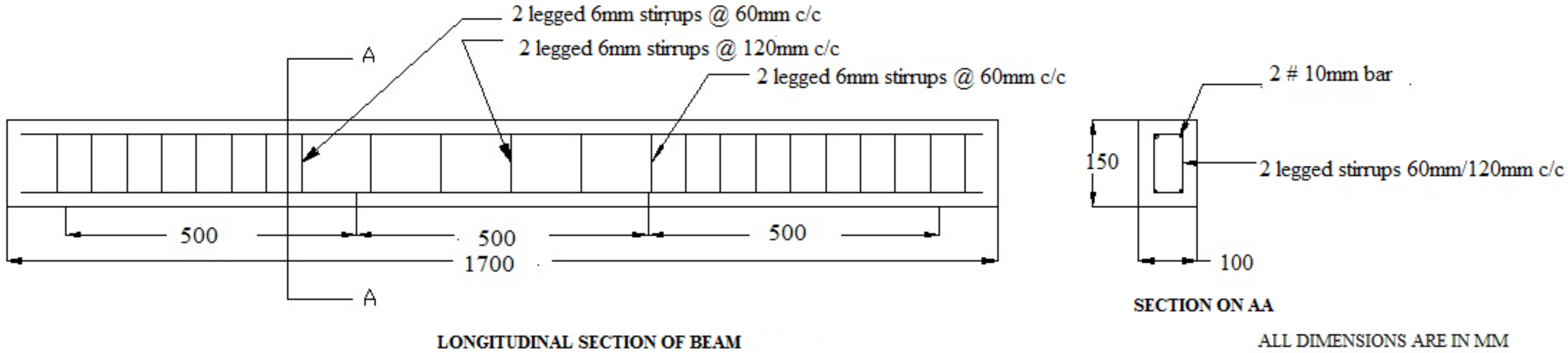
2.2.2. Beam Design and Preparation
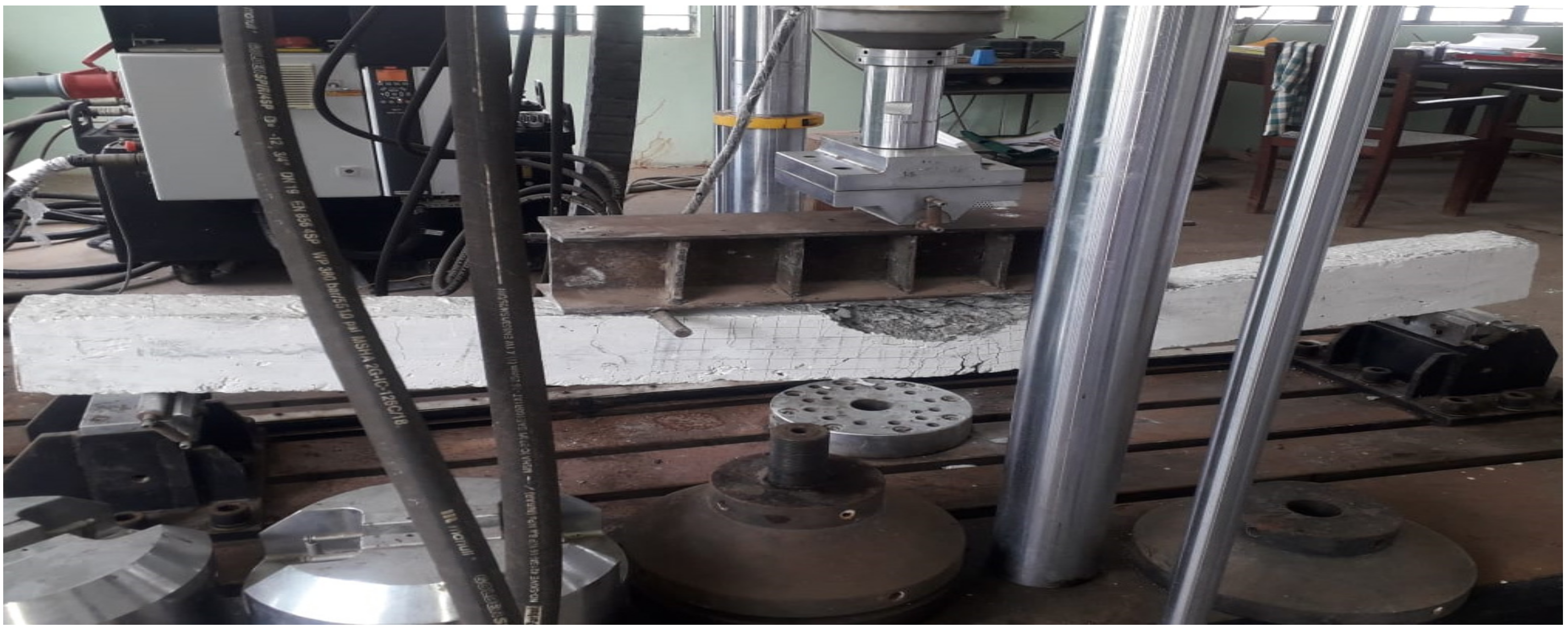
2.2.3. Loading Setup
2.2.4. Testing Procedure
3. Results and Discussions
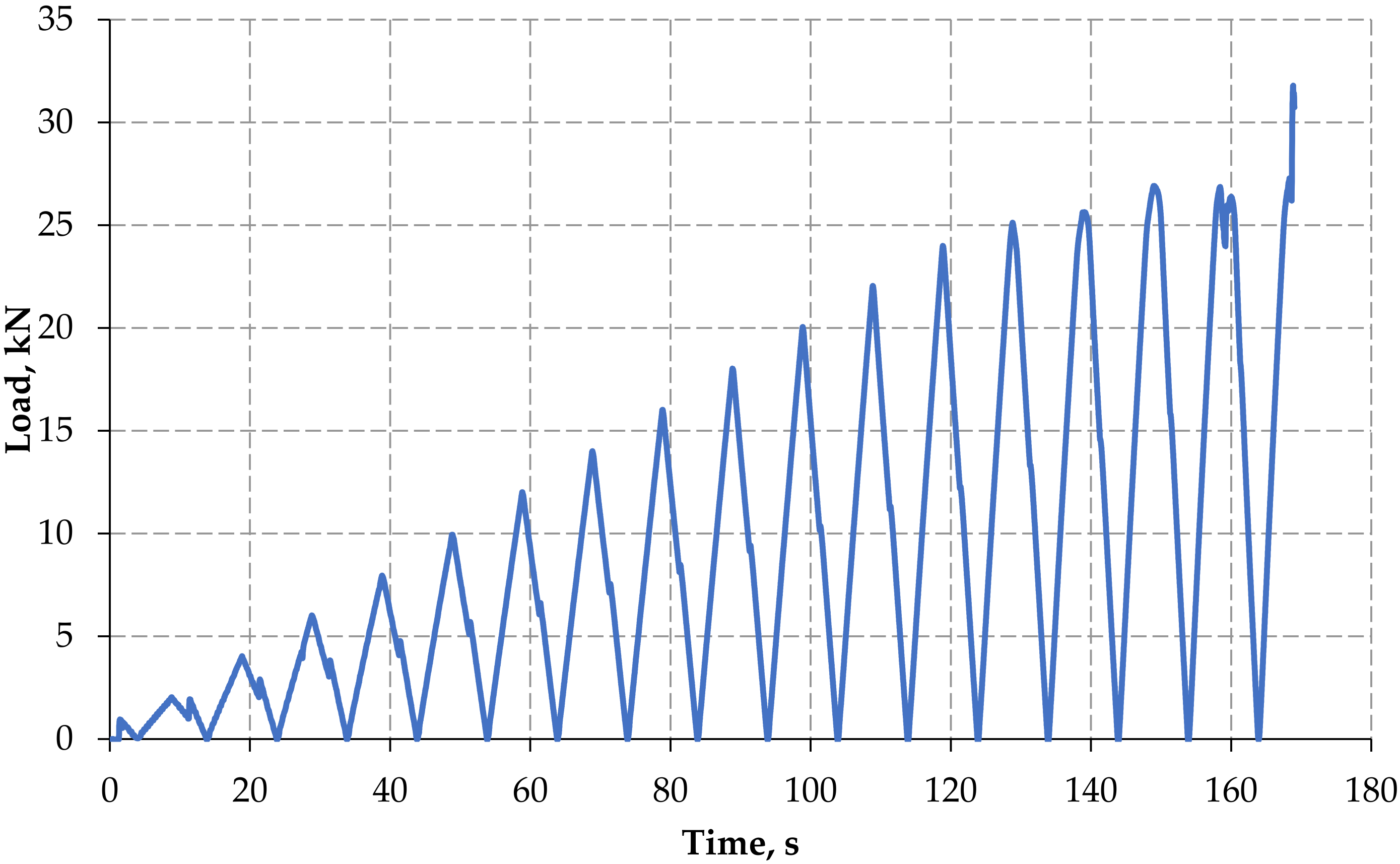
3.1. Monotonic and Forwarded Cyclic Load
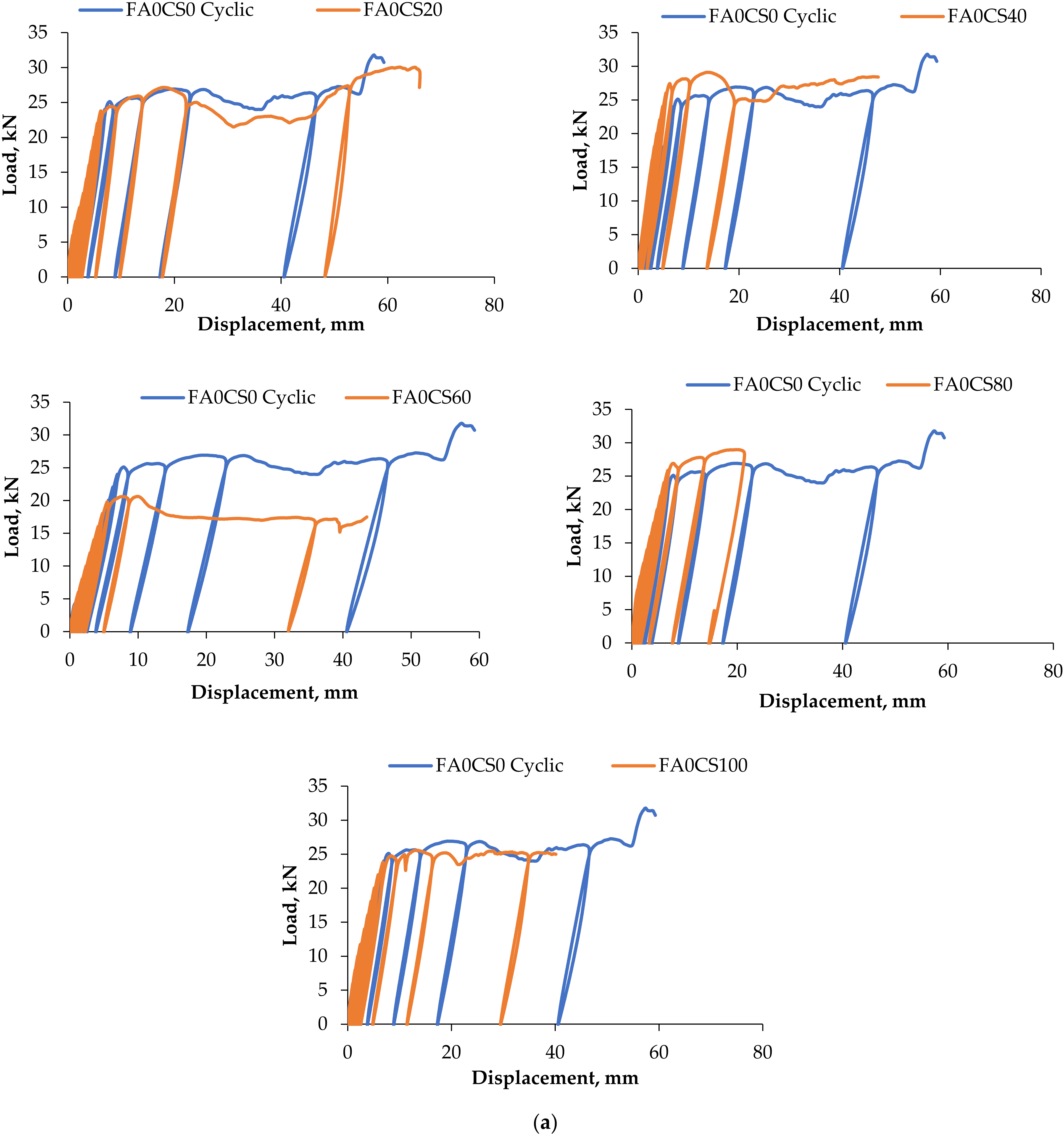
3.2. Load–Deflection Behaviour
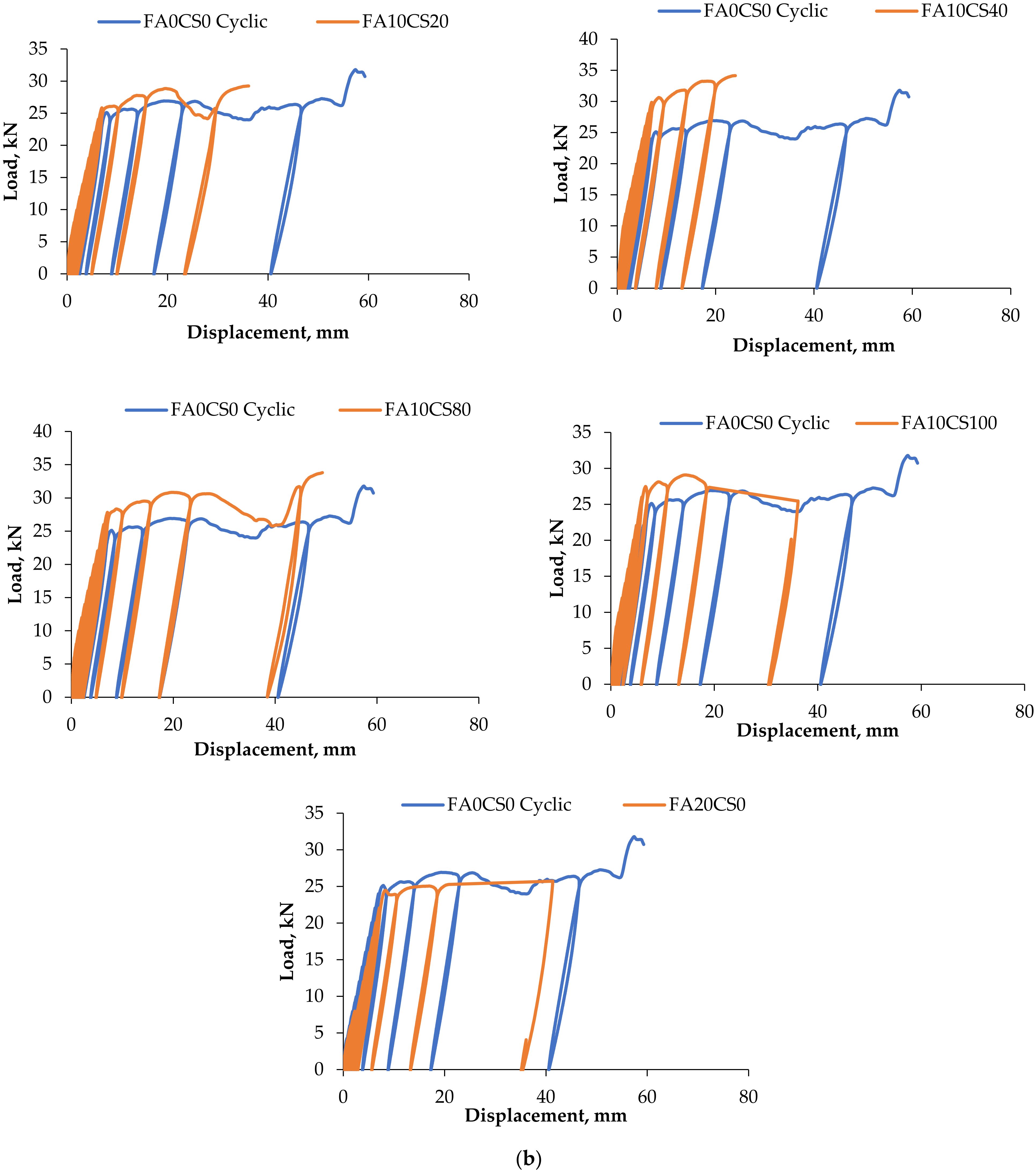
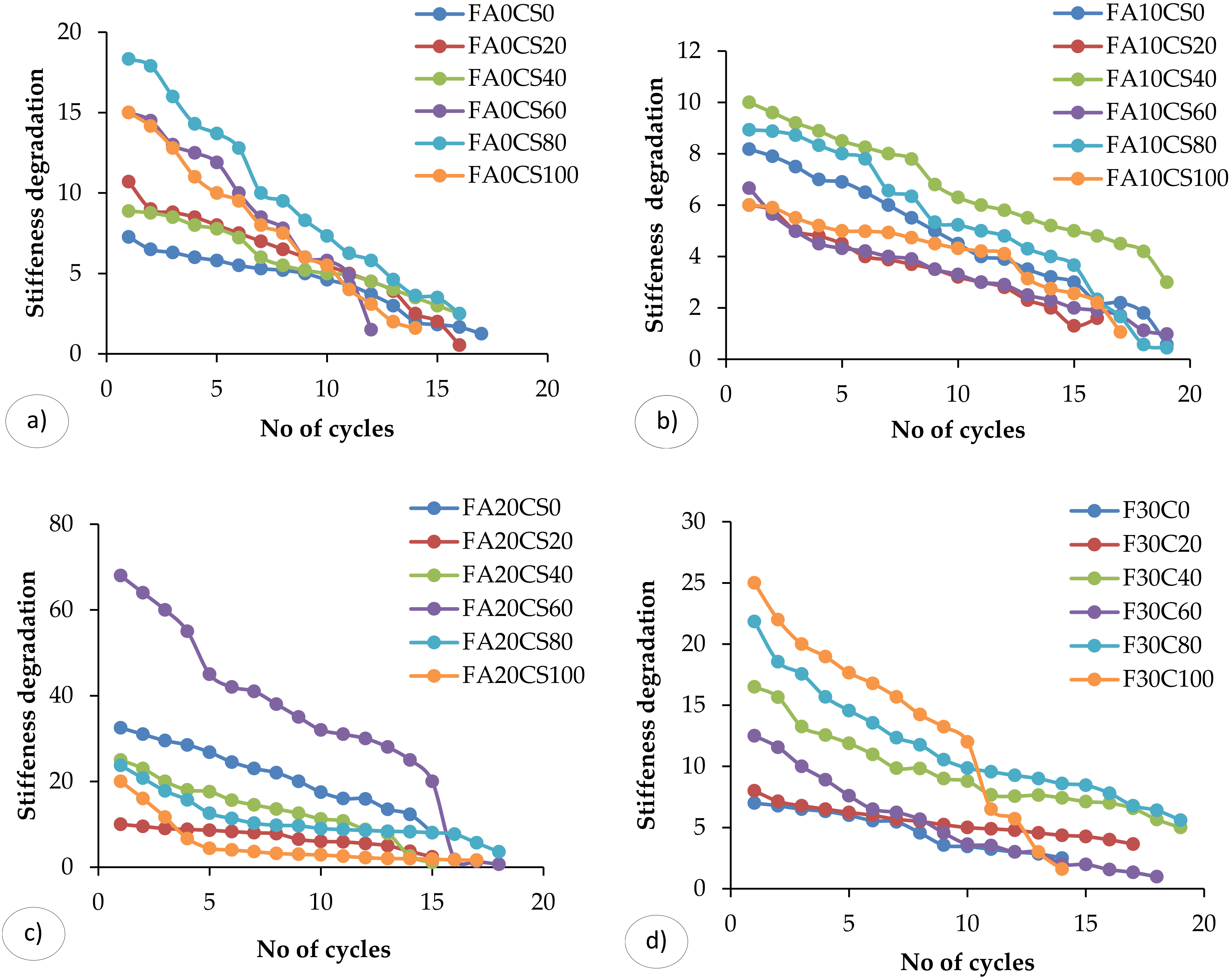
3.3. Stiffness Degradation
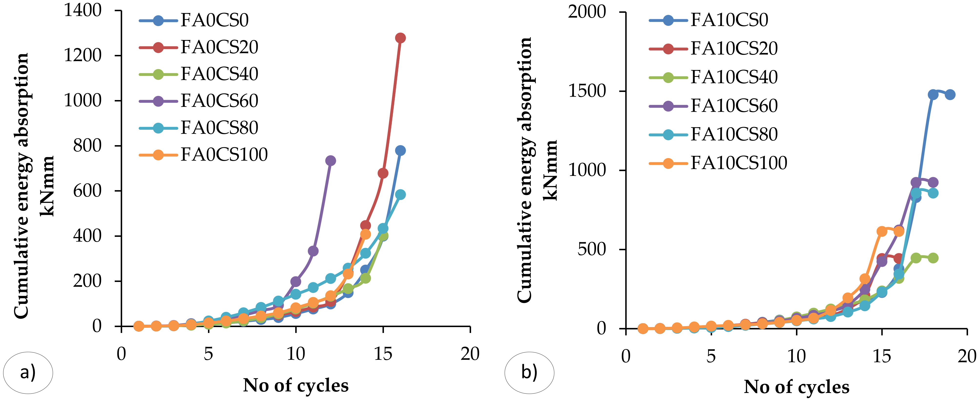
3.4. Energy Absorption Capacity
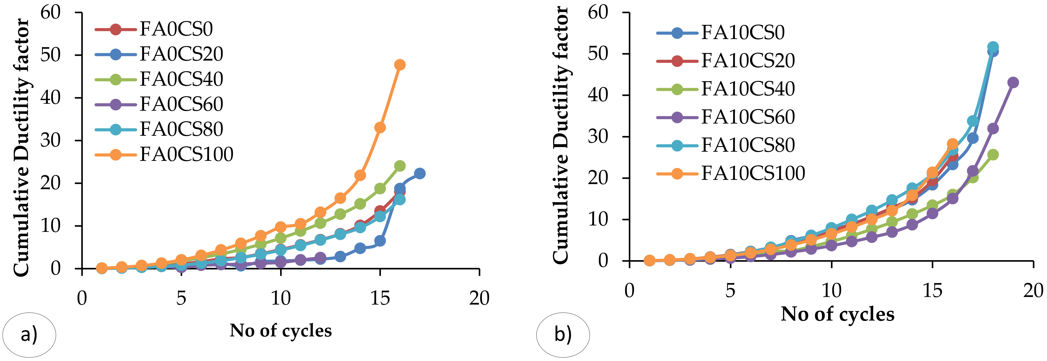
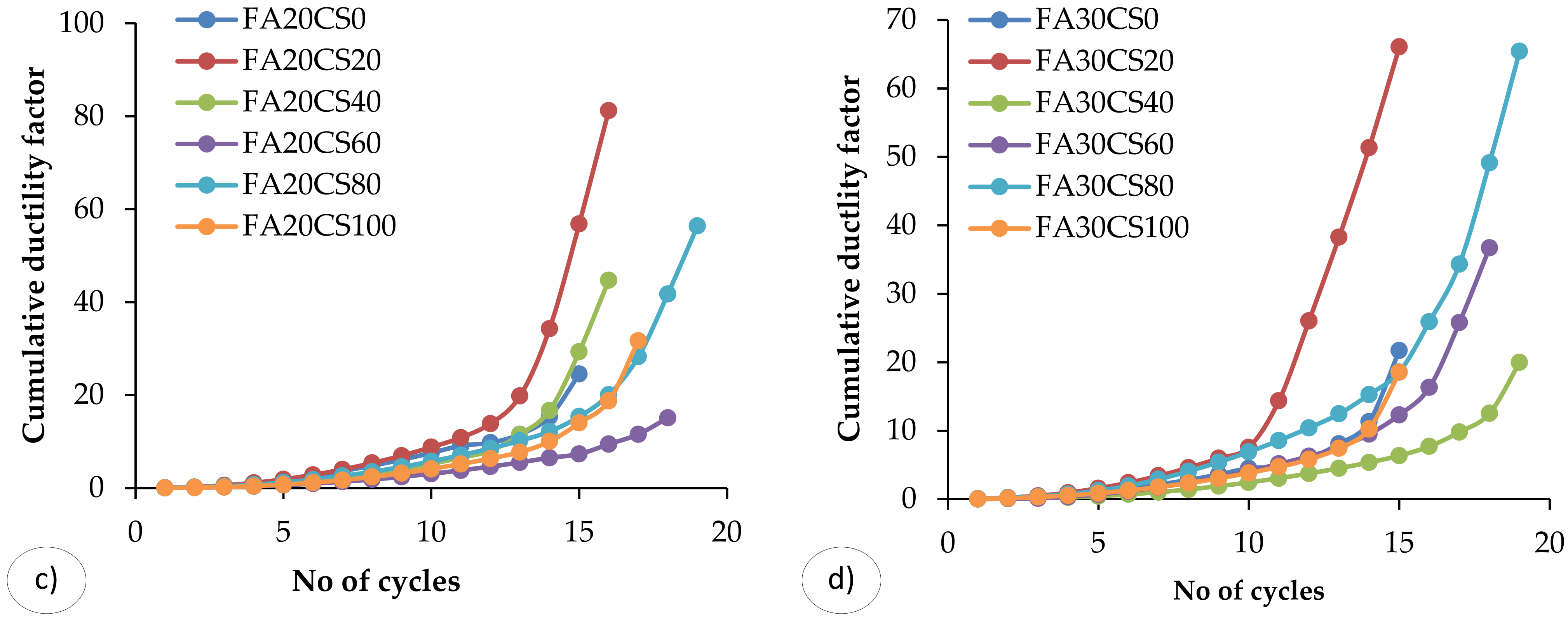
3.5. Ductility Factor
3.6. Failure Pattern
4. Comparison of Experimental Results with Previous Literatures
5. Conclusions
- -
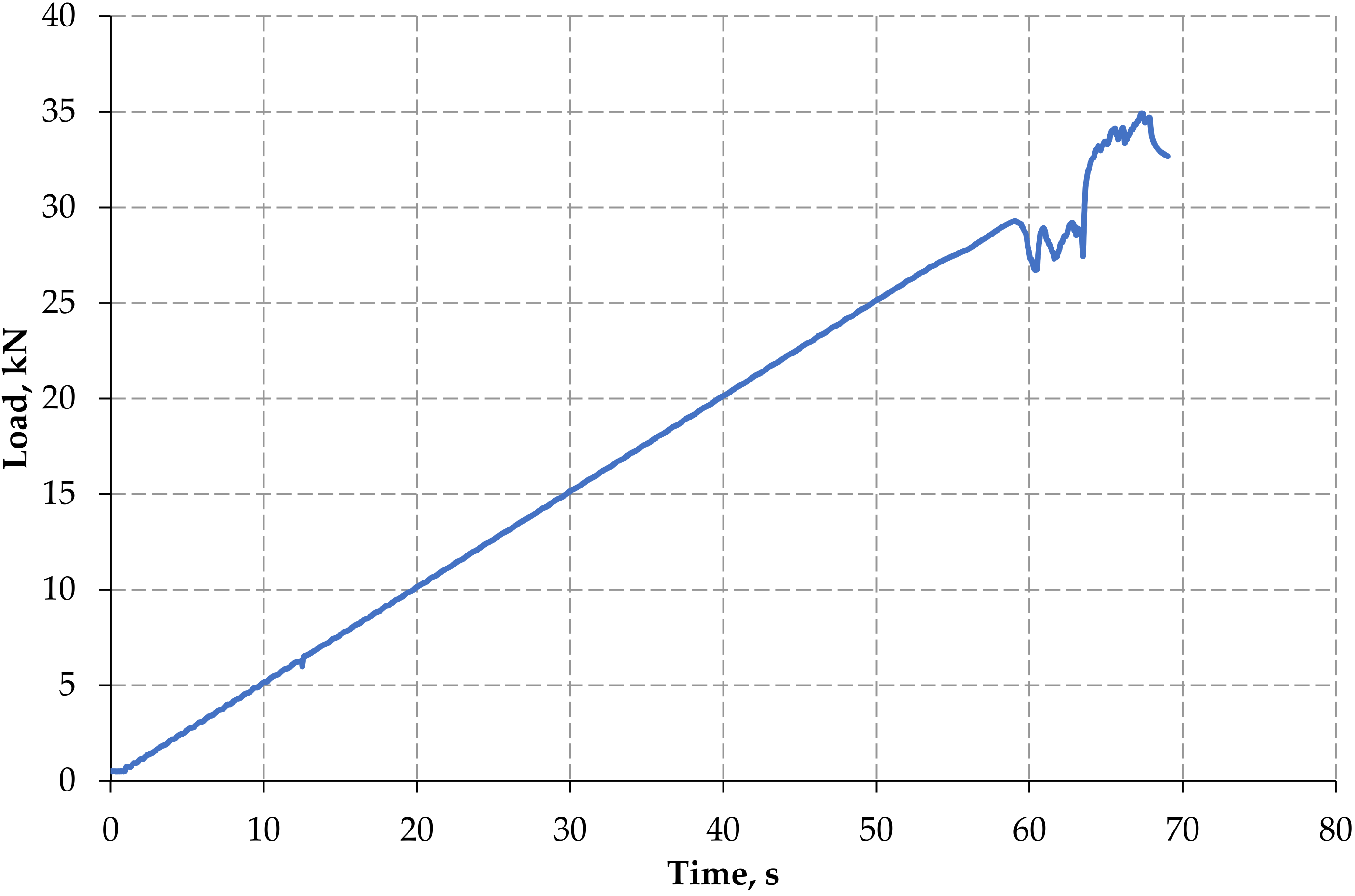
- During the monotonic loading condition, the control concrete RC beam withstands the ultimate load of 35kN. The first crack was observed at the load of 15.17 kN. It was found that when the specimen loaded under cyclic loading condition, the control concrete beam withstands the ultimate load of 31.78 kN, and the first crack was observed at the load point of 9.94 kN.
- -
- It was found that the specimens with 20% FA and 80% CS (FA20CS80) possesses higher ultimate load carrying capacity compared to the control concrete beam. It withstands up to 18 cycles of loading with ultimate deflection which was 60 mm.
- -
- The stiffness of the structural members gradually decreases with increasing cycles of loading. RCC beam FA30CS20 has 34.78% more stiffness compared to the control concrete beam, and, also, the percentage reduction is less.
- -
- The beam FA20CS20 has 77.85% higher ductility factor than the control beam, whereas the beam FA0CS60 has 37.22% lower ductility factor than the control beam. The beam FA30CS40 has 90.66% lower energy absorption capacity than the control beam, whereas the beam FA30CS80 has 69.2% higher energy absorption capacity than the control beam.
- -
- The CS and FA admixed RCC beams have shown excellent ultimate load carrying capacity, stiffness, energy absorption capacity, and ductility factor compared to the control concrete beam. Because, the density and the stiffness of concrete are increased, due to irregular surfaces of CS filled with hydration products.
- -
- At ultimate load condition, the beams fail with the crushing of concrete at the top compression region. However, none of the beams has a shear failure. It indicates that the shear reinforcement provided is sufficient to carry the shear.
- -
- It is also proposed that when determining the CS replacement amount, the required concrete compressive strength be taken into account.
Author Contributions
Funding
Institutional Review Board Statement
Informed Consent Statement
Data Availability Statement
Acknowledgments
Conflicts of Interest
References
- Gil-Martín, L.M.; Rodríguez-Suesca, A.E.; Fernández-Ruiz, M.A.; Hernández-Montes, E. Cyclic behavior of RC Beam-Column joints with epoxy resin and ground tire rubber as partial cement replacement. Constr. Build. Mater. 2019, 211, 659–674. [Google Scholar] [CrossRef]
- Murad, Y.; Al-Bodour, W.; Abu-Hajar, H. Cyclic behavior of RC Beam-Column joints made with sustainable concrete. Int. Rev. Civ. Eng. 2019, 10, 301–311. [Google Scholar] [CrossRef]
- Faleschini, F.; Bragolusi, P.; Zanini, M.A.; Zampieri, P.; Pellegrino, C. Experimental and numerical investigation on the cyclic behavior of RC beam column joints with EAF slag concrete. Eng. Struct. 2017, 152, 335–347. [Google Scholar] [CrossRef]
- Said, S.H.; Razak, H.A. Structural behavior of RC engineered cementitious composite (ECC) exterior beam-column joints under reversed cyclic loading. Constr. Build. Mater. 2016, 107, 226–234. [Google Scholar] [CrossRef]
- Hassanli, R.; Youssf, O.; Mills, J.E. Experimental investigations of reinforced rubberized concrete structural members. J. Build. Eng. 2017, 10, 149–165. [Google Scholar] [CrossRef]
- Kwan, A.K.H.; Ho, J.C.M.; Pam, H.J. Effects of concrete grade and steel yield strength on flexural ductility of reinforced concrete beams. Aust. J. Struct. Eng. 2004, 5, 1–20. [Google Scholar] [CrossRef]
- Raju, S.; Dharmar, B. Mechanical properties of concrete with Copper Slag and Fly Ash by DT and NDT. Period. Polytech. Civ. Eng. 2016, 60, 313–322. [Google Scholar] [CrossRef] [Green Version]
- Raju, S.; Dharmar, B. Studies on flexural behavior of reinforced concrete beams with copper slag and fly ash. Struct. Concr. 2020, 21, 107–116. [Google Scholar] [CrossRef]
- Chakrawarthi, V.; Darmar, B.; Elangovan, A. Copper slag concrete admixed with polypropylene fibres. Gradjevinar 2016, 68, 95–104. [Google Scholar] [CrossRef] [Green Version]
- Vijayaprabha, C.; Brindha, D.; Siva, A. Durability performance of copper slag concrete admixed with polypropylene fiber. J. Struct. Eng. 2017, 43, 598–606. [Google Scholar]
- Arivalagan, S. Experimental Study on the Flexural Behavior of Reinforced Concrete Beams as Replacement of Copper Slag as Fine Aggregate. J. Civ. Eng. Urban. 2013, 3, 176–182. [Google Scholar]
- Siddique, R.; Singh, M.; Jain, M. Recycling copper slag in steel fibre concrete for sustainable construction. J. Clean. Prod. 2020, 271, 122559. [Google Scholar] [CrossRef]
- Rajasekar, A.; Arunachalam, K.; Kottaisamy, M. Assessment of strength and durability characteristics of copper slag incorporated ultra high strength concrete. J. Clean. Prod. 2019, 208, 402–414. [Google Scholar] [CrossRef]
- Al-Jabri, K.S.; Hisada, M.; Al-Oraimi, S.K.; Al-Saidy, A.H. Copper slag as sand replacement for high performance concrete. Cem. Concr. Compos. 2009, 31, 483–488. [Google Scholar] [CrossRef]
- Hwang, C.L.; Laiw, J.C. Properties of concrete using copper slag as a substitute for fine aggregate. In ACI Special Publication; American Concrete Institute: Farmington Hills, MI, USA, 1989; Volume 114, pp. 1677–1695. [Google Scholar]
- Khanzadi, M.; Behnood, A. Mechanical properties of High-Strength concrete incorporating copper slag as coarse aggregate. Constr. Build. Mater. 2009, 23, 2183–2188. [Google Scholar] [CrossRef]
- Amran, M.; Huang, S.S.; Debbarma, S.; Rashid, R.S. Fire resistance of geopolymer concrete: A critical review. Constr. Build. Mater. 2022, 324, 126722. [Google Scholar] [CrossRef]
- Mohan, M.; Sharma, S. Air quality assessment from thermal power plants in National Capital Region India: A case study. Indian J. Environ. Prot. 2008, 28, 116–128. [Google Scholar]
- Haque, M.E. Indian Fly-Ash: Production and consumption scenario. Int. J. Waste Resour. 2013, 3, 22–25. [Google Scholar] [CrossRef]
- Muthalvan, R.S.; Ravikumar, S.; Avudaiappan, S.; Amran, M.; Aepuru, R.; Vatin, N.; Fediuk, R. The Effect of Superabsorbent Polymer and Nano-Silica on the Properties of Blended Cement. Crystals 2021, 11, 1394. [Google Scholar] [CrossRef]
- Amran, Y.H.M.; Soto, M.G.; Alyousef, R.; El-Zeadani, M.; Alabduljabbar, H.; Aune, V. Performance investigation of High-Proportion Saudi-Fly-Ash-Based concrete. Results Eng. 2020, 6, 100118. [Google Scholar] [CrossRef]
- Amran, M.; Fediuk, R.; Murali, G.; Avudaiappan, S.; Ozbakkaloglu, T.; Vatin, N.; Karelina, M.; Klyuev, S.; Gholampour, A. Fly Ash-Based Eco-Efficient concretes: A comprehensive review of the Short-Term properties. Materials 2021, 14, 4264. [Google Scholar] [CrossRef] [PubMed]
- Haruna, S.; Mohammed, B.S.; Wahab, M.M.A.; Kankia, M.U.; Amran, M.; Gora, A.M. Long-Term Strength Development of Fly Ash-Based One-Part Alkali-Activated Binders. Materials 2021, 14, 4160. [Google Scholar] [CrossRef] [PubMed]
- Onaizi, A.M.; Lim, N.H.A.S.; Huseien, G.F.; Amran, M.; Ma, C.K. Effect of the addition of nano glass powder on the compressive strength of high volume fly ash modified concrete. Mater. Today Proc. 2021, 48, 1789–1795. [Google Scholar] [CrossRef]
- Amran, M.; Debbarma, S.; Ozbakkaloglu, T. Fly Ash-Based Eco-Friendly geopolymer concrete: A critical review of the Long-Term durability properties. Constr. Build. Mater. 2021, 270, 121857. [Google Scholar] [CrossRef]
- Amran, Y.H.M. Influence of structural parameters on the properties of Fibred-Foamed concrete. Innov. Infrastruct. Solut. 2020, 5, 16. [Google Scholar] [CrossRef]
- Al-Fakih, A.; Mohammed, B.S.; Wahab, M.M.A.; Liew, M.S.; Amran, Y.H.M. Flexural behavior of rubberized concrete interlocking masonry walls under Out-Of-Plane load. Constr. Build. Mater. 2020, 263, 120661. [Google Scholar] [CrossRef]
- Amran, Y.H.M.; Alyousef, R.; Alabduljabbar, H.; Khudhair, M.H.R.; Hejazi, F.; Alaskar, A.; Alrshoudi, F.; Siddika, A. Performance properties of structural Fibred-Foamed concrete. Results Eng. 2020, 5, 100092. [Google Scholar] [CrossRef]
- Bui, P.T.; Ogawa, Y.; Nakarai, K.; Kawai, K.; Sato, R. Internal curing of Class-F Fly-Ash concrete using High-Volume Roof-Tile waste aggregate. Mater. Struct. Constr. 2017, 50, 203. [Google Scholar] [CrossRef]
- Havanagi, V.G.; Mathur, S.; Prasad, P.S.; Kamaraj, C. Feasibility of copper Slag-Fly Ash-Soil mix as a road construction material. Transp. Res. Rec. 2007, 2, 13–20. [Google Scholar] [CrossRef]
- Chakrawarthi, V.; Avudaiappan, S.; Amran, M.; Dharmar, B.; Jesuarulraj, L.R.; Fediuk, R.; Aepuru, R.; Vatin, N.; Saavedra Flores, E. Impact Resistance of Polypropylene Fibre-Reinforced Alkali–Activated Copper Slag Concrete. Materials 2021, 14, 7735. [Google Scholar] [CrossRef]
- Subash, N.; Avudaiappan, S.; Kumar, S.A.; Amran, M.; Vatin, N.; Fediuk, R.; Aepuru, R. Experimental Investigation on Geopolymer Concrete with Various Sustainable Mineral Ashes. Materials 2021, 14, 7596. [Google Scholar] [CrossRef] [PubMed]
- Yazici, Ş.; Arel, H.Ş. Effects of fly ash fineness on the mechanical properties of concrete. Sadhana—Acad. Proc. Eng. Sci. 2012, 37, 389–403. [Google Scholar] [CrossRef] [Green Version]
- Wu, W.; Zhang, W.; Ma, G. Optimum content of copper slag as a fine aggregate in high strength concrete. Mater. Des. 2010, 31, 2878–2883. [Google Scholar] [CrossRef]
- Amran, M.; Murali, G.; Khalid, N.H.A.; Fediuk, R.; Ozbakkaloglu, T.; Lee, Y.H.; Haruna, S.; Lee, Y.Y. Slag uses in making an ecofriendly and sustainable concrete: A review. Constr. Build. Mater. 2021, 272, 121942. [Google Scholar] [CrossRef]
- Arularasi, V.; Thamilselvi, P.; Avudaiappan, S.; Flores, E.I.S.; Amran, M.; Fediuk, R.; Vatin, N.; Karelina, M. Rheological behavior and strength characteristics of cement paste and mortar with fly ash and GGBS admixtures. Sustainability 2021, 13, 9600. [Google Scholar] [CrossRef]
- Mobasher, B.; Devaguptapu, R.; Arino, A.M. Effect of copper slag on the hydration of blended cementitious mixtures. In Proceedings of the Materials Engineering Conference, Washington, DC, USA, 10–14 November 1996; Volume 2, pp. 1677–1686. [Google Scholar]
- Shoya, M.; Nagataki, S.; Tomosawa, F.; Sugita, S. Freezing and thawing resistance of concrete with excessive bleeding and its improvement. In ACI Special Publication; American Concrete Institute: Farmington Hills, MI, USA, 1997; Volume SP. [Google Scholar]
- Abdelgader, H.S.; Kurpińska, M.; Amran, M. Effect of slag coal ash and foamed glass on the mechanical properties of Two-Stage concrete. Mater. Today Proc. 2022, 1, 12. [Google Scholar] [CrossRef]
- Brindha, D.; Nagan, S. Durability studies on copper slag admixed concrete. Asian J. Civ. Eng. 2011, 12, 563–578. [Google Scholar]
- Palani, T.; Jaya, K.P.; Muthumani, K. Studies on copper slag substitution for sand in high strength concrete. J. Struct. Eng. 2014, 41, 293–306. [Google Scholar]
- Velumani, M.; Nirmalkumar, K. Durability and characteristics of copper slag as fine aggregate and fly ash as cement in concrete. In Proceedings of the 2nd International Conference on Current Trends in Engineering and Technology, ICCTET 2014, Coimbatore, India, 8 July 2014; pp. 222–227. [Google Scholar]
- Uysal, M.; Akyuncu, V. Durability performance of concrete incorporating Class F and Class C fly ashes. Constr. Build. Mater. 2012, 34, 170–178. [Google Scholar] [CrossRef]
- Novitasari, Y.; Pratama, M.M.A.; Sulton, M.; Nindyawati, N. Ductility analysis of graded concrete beams on maximum reinforcement ratio. In Proceedings of the AIP 3rd International Conference of Green Civil and Environmenal Engineering, Malang, Indonesia, 12 August 2021; Volume 2447. [Google Scholar]
- Hong, C.W.; Lee, J.I.; Ryu, J.H. Effect of copper slag as a fine aggregate on the properties of concrete. J. Ceram. Process. Res. 2017, 18, 324–328. [Google Scholar]
- Lakusic, S. Durability characteristics of copper slag concrete with fly ash. J. Croat. Assoc. Civ. Eng. 2017, 69, 1031–1040. [Google Scholar] [CrossRef] [Green Version]
- IS 9103. Concrete Admixtures—Specification; Bureau of Indian Standards: New Delhi, India, 2003; 22p. [Google Scholar]
- ASTM C1585. Standard Test Method for Measurement of Rate of Absorption of Water by Hydraulic Cement Concretes; ASTM International: West Conshohocken, PA, USA, 2011. [Google Scholar]
- IS 383. Specification for Coarse and Fine Aggregates from Natural Sources for Concrete; Bureau of Indian Standards: New Delhi, India, 1970; 19p. [Google Scholar]
- IS 4926. Code of Practice Ready-Mixed Concrete; Bureau of Indian Standards: New Delhi, India, 2003; 23p. [Google Scholar]
- IS 3812. Specification for Pulverized Fuel Ash. Part-1: For Use as Pozzolana in Cement, Cement Mortar and Concrete; Bureau of Indian Standards: New Delhi, India, 2013; pp. 1–12. [Google Scholar]
- Murali, G.; Prasad, N.; Klyuev, S.; Fediuk, R.; Abid, S.R.; Amran, M.; Vatin, N. Impact Resistance of Functionally Layered Two-Stage Fibrous Concrete. Fibers 2021, 9, 88. [Google Scholar] [CrossRef]
- Shi, C.; Meyer, C.; Behnood, A. Utilization of copper slag in cement and concrete. Resour. Conserv. Recycl. 2008, 52, 1115–1120. [Google Scholar] [CrossRef]
- Tixier, R.; Devaguptapu, R.; Mobasher, B. The effect of copper slag on the hydration and mechanical properties of cementitious mixtures. Cem. Concr. Res. 1997, 27, 1569–1580. [Google Scholar] [CrossRef]
- BIS:10262. Indian Standard Guidelines for Concrete Mix Design Proportioning; Bureau of Indian Standards: New Delhi, India, 2009. [Google Scholar]
- Amran, M.; Fediuk, R.; Abdelgader, H.S.; Murali, G.; Ozbakkaloglu, T.; Lee, Y.H.; Lee, Y.Y. Fiber-reinforced alkali-activated concrete: A review. J. Build. Eng. 2022, 45, 103638. [Google Scholar] [CrossRef]
- Avudaiappan, S.; Prakatanoju, S.; Amran, M.; Aepuru, R.; Saavedra Flores, E.I.; Das, R.; Gupta, R.; Fediuk, R.; Vatin, N. Experimental Investigation and Image Processing to Predict the Properties of Concrete with the Addition of Nano Silica and Rice Husk Ash. Crystals 2021, 11, 1230. [Google Scholar] [CrossRef]
- IS 456:2000. Indian Standard Plain and Reinforced Concrete—Code of Practice; Bureau of Indian Standards: New Delhi, India, 2000. [Google Scholar]
- Vijayaprabha, C.; Brindha, D. Investigation on cyclic behaviour of FRC beams incorporating copper slag as sustainable waste. J. Mater. Eng. Struct. 2020, 7, 293–306. [Google Scholar]
- Chidambaram, K.R.S.; Thirugnanam, G.S. Comparative Study on Behaviour of Reinforced Beam-Column Joints with Reference to Anchorage Detailing. J. Civ. Eng. Res. 2012, 2, 12–17. [Google Scholar] [CrossRef]


| Physical Properties | Cement |
|---|---|
| Specific gravity | 3.15 |
| Normal consistency (%) | 34% |
| Initial setting time (minutes) | 90 |
| Final setting time (minutes) | 420 |
| Specification | Fine Aggregate | Copper Slag | Coarse Aggregate |
|---|---|---|---|
| Specific gravity | 2.51 | 3.52 | 2.75 |
| Fineness modulus | 2.79 | 3.6 | 7.6 |
| Bulk Density kg/m3 | 1420 | 1750 | 1380 |
| Void ratio | 0.77 | 0.8 | 0.95 |
| Water absorption % | 1.08 | 0.13 | 0.45 |
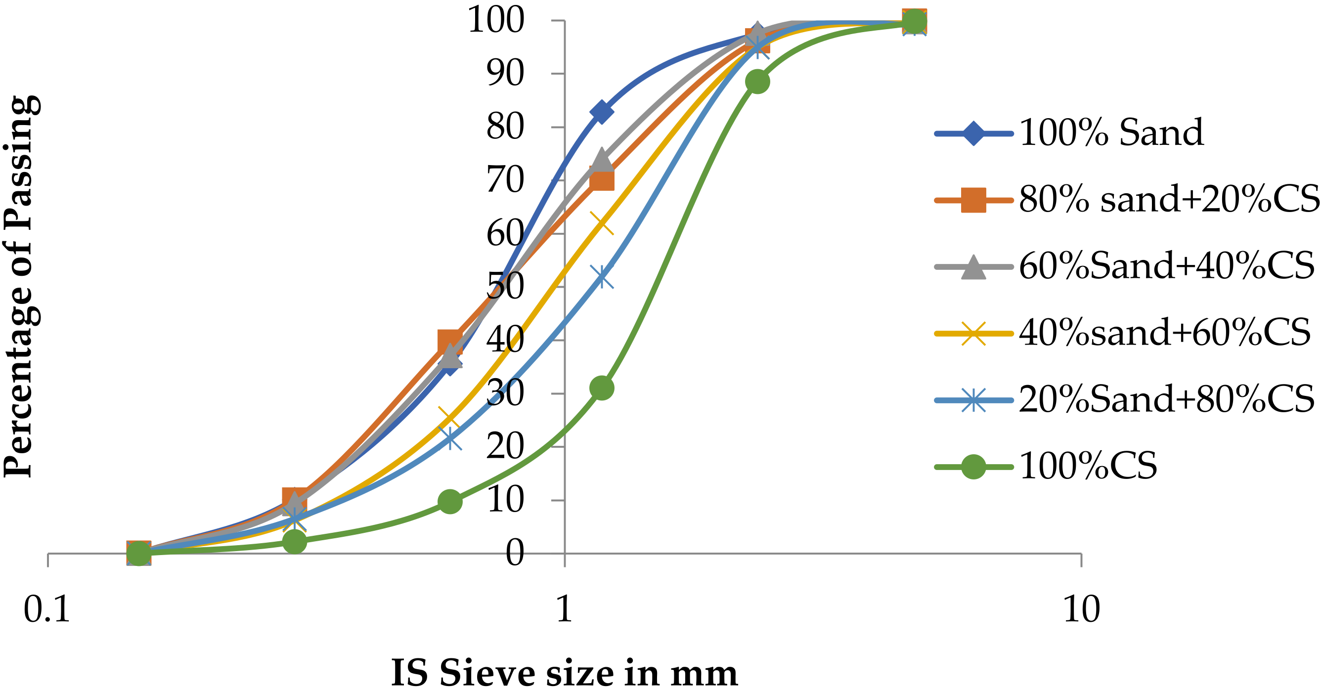
| IS Sieve Size | Cumulative Percentage Passing, % | |||||
|---|---|---|---|---|---|---|
| 100% Sand | 80% Sand and 20% CS | 60% Sand and 40% CS | 40% Sand and 60% CS | 20% Sand and 80% CS | 100% CS | |
| 4.75 | 99.9 | 99.92 | 99.76 | 99.66 | 99.29 | 99.85 |
| 2.36 | 97.4 | 96.21 | 97.60 | 94.96 | 94.94 | 88.55 |
| 1.18 | 82.8 | 70.41 | 73.98 | 61.99 | 51.95 | 31.05 |
| 0.6 | 35.6 | 39.70 | 37.15 | 25.42 | 21.60 | 9.7 |
| 0.3 | 10.1 | 10.05 | 9.38 | 6.22 | 6.47 | 2.2 |
| 0.15 | 0.03 | 0.06 | 0.05 | 0.03 | 0.03 | 0.011 |
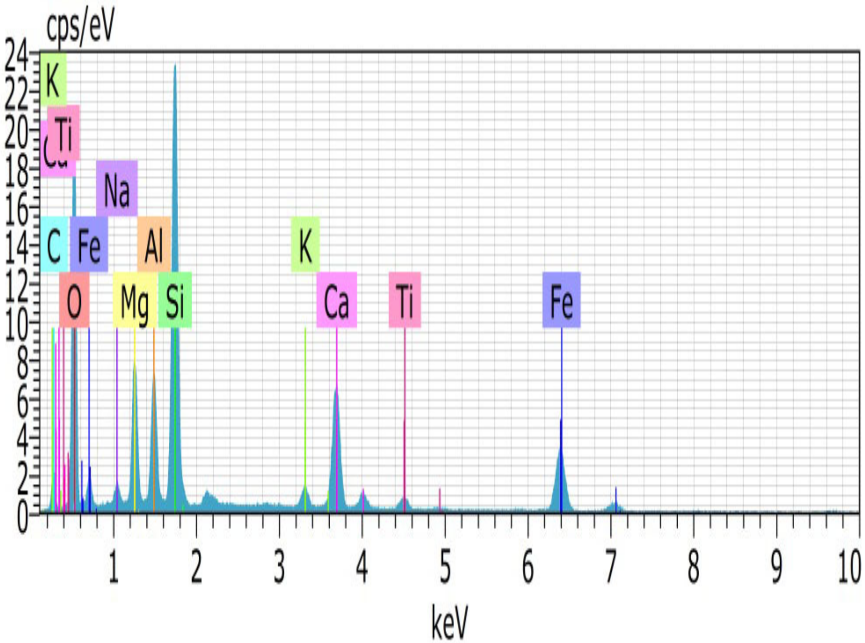
| Chemical Components | Fly Ash | CS |
|---|---|---|
| O | 50.65 | 45.96 |
| Si | 18.67 | 12.87 |
| Fe | 3.07 | 9.73 |
| Ca | 10.2 | 8.79 |
| C | 6.49 | 8.55 |
| Mg | 0.22 | 5.73 |
| Al | 19.6 | 4.59 |
| Na | - | 1.31 |
| Ti | 0.47 | 1.27 |
| K | 0.83 | 1.19 |
| Mix Identification | Cement kg/m3 | Fly Ash kg/m3 | Fine Aggregate kg/m3 | Copper Slag kg/m3 | Coarse Aggregate kg/m3 | Water kg/m3 |
|---|---|---|---|---|---|---|
| FA0CS0 | 380 | - | 596 | - | 1293 | 152 |
| FA0CS20 | 380 | 0 | 520 | 183 | 1293 | 152 |
| FA0CS40 | 380 | 0 | 390 | 366 | 1293 | 152 |
| FA0CS60 | 380 | 0 | 260 | 549 | 1293 | 152 |
| FA0CS80 | 380 | 0 | 131 | 738 | 1293 | 152 |
| FA0CS100 | 380 | 0 | 0 | 922 | 1293 | 152 |
| FA10CS0 | 342 | 38 | 596 | 0 | 1293 | 152 |
| FA10CS20 | 342 | 38 | 520 | 183 | 1293 | 152 |
| FA10CS40 | 342 | 38 | 390 | 366 | 1293 | 152 |
| FA10CS60 | 342 | 38 | 260 | 549 | 1293 | 152 |
| FA10CS80 | 342 | 38 | 131 | 738 | 1293 | 152 |
| FA10CS100 | 342 | 38 | 0 | 922 | 1293 | 152 |
| FA20CS0 | 304 | 76 | 596 | 0 | 1293 | 152 |
| FA20CS20 | 304 | 76 | 520 | 183 | 1293 | 152 |
| FA20CS40 | 304 | 76 | 390 | 366 | 1293 | 152 |
| FA20CS60 | 304 | 76 | 260 | 549 | 1293 | 152 |
| FA20CS80 | 304 | 76 | 131 | 738 | 1293 | 152 |
| FA20CS100 | 304 | 76 | 0 | 922 | 1293 | 152 |
| FA30CS0 | 266 | 114 | 596 | 0 | 1293 | 152 |
| FA30CS20 | 266 | 114 | 520 | 183 | 1293 | 152 |
| FA30CS40 | 266 | 114 | 390 | 366 | 1293 | 152 |
| FA30CS60 | 266 | 114 | 260 | 549 | 1293 | 152 |
| FA30CS80 | 266 | 114 | 131 | 738 | 1293 | 152 |
| FA30CS100 | 266 | 114 | 0 | 922 | 1293 | 152 |
| Mix Identification | Average Compressive Strength, MPa | Rate of Strength Development | |||||
|---|---|---|---|---|---|---|---|
| (σc)3 | (σc)7 | (σc)14 | (σc)28 | (σc)56 | (σc)90 | ||
| FA0CS0 | 30.22 | 38.22 | 39.77 | 43.25 | 47.7 | 50.07 | 0 |
| FA0CS20 | 30.66 | 33.41 | 35.25 | 38.22 | 47.11 | 49.78 | ↓ 0.6 |
| FA0CS40 | 31.55 | 36.7 | 39.55 | 44.74 | 48 | 53.33 | 6.5 |
| FA0CS60 | 23.85 | 27.11 | 36.44 | 38.81 | 41.04 | 44.14 | ↓ 11.8 |
| FA0CS80 | 24.15 | 27.55 | 35.11 | 39.7 | 42.59 | 45.92 | ↓ 8.3 |
| FA0CS100 | 24.15 | 25.77 | 29.04 | 33.77 | 38.52 | 44.88 | ↓ 10.4 |
| FA10CS0 | 26.66 | 29.77 | 35.73 | 37.33 | 46.52 | 48.59 | ↓ 7.7 |
| FA10CS20 | 27.55 | 37.34 | 42.22 | 44.74 | 46.11 | 48.9 | ↓ 2.7 |
| FA10CS40 | 30.66 | 44.59 | 45.77 | 48.9 | 50.52 | 57.03 | 11.3 |
| FA10CS60 | 26.22 | 40.59 | 42.66 | 44.45 | 47.8 | 55.91 | 4.8 |
| FA10CS80 | 24.44 | 32 | 39.55 | 41.9 | 48 | 51.56 | 16.9 |
| FA10CS100 | 23.55 | 37.77 | 40.25 | 45.32 | 49.03 | 51.85 | 11.0 |
| FA20CS0 | 17.77 | 28.68 | 33.77 | 34.67 | 39.11 | 46.22 | ↓ 13.0 |
| FA20CS20 | 18.66 | 35.11 | 36.88 | 37.93 | 46.23 | 48.7 | 1.3 |
| FA20CS40 | 20.88 | 36 | 37.77 | 44.7 | 52.01 | 55.73 | 3.0 |
| FA20CS60 | 20.88 | 36.91 | 37.77 | 43 | 48.01 | 52.45 | 0.3 |
| FA20CS80 | 16.44 | 34.67 | 38.22 | 51.23 | 53.92 | 58.51 | 17.8 |
| FA20CS100 | 16 | 33.18 | 36 | 45.48 | 47.27 | 55.6 | 12.7 |
| FA30CS0 | 16 | 29.33 | 35.85 | 36.56 | 40.44 | 43.55 | ↓ 7.7 |
| FA30CS20 | 16.88 | 31.55 | 34.81 | 38.22 | 47.85 | 50.7 | ↓ 2.7 |
| FA30CS40 | 24.88 | 27.55 | 33.33 | 43.26 | 50.24 | 51.57 | 11.3 |
| FA30CS60 | 25.33 | 26.52 | 36.44 | 40.44 | 41.77 | 50.2 | 4.8 |
| FA30CS80 | 25.77 | 40.45 | 40.88 | 46.5 | 55 | 58.96 | 16.9 |
| FA30CS100 | 21.77 | 39.55 | 40 | 47.7 | 55.11 | 56.44 | 11.0 |
| Mix Identification | Load at First Crack (kN) | Deflection at First Crack (mm) | No. of Cycles at First Crack | Ultimate Load kN | Ultimate Deflection in mm | No. of Cycles at Ultimate Load | No. of Cracks |
|---|---|---|---|---|---|---|---|
| FA0CS0 | 9.94 | 2.49 | 5 | 31.78 | 57.35 | 16 | 11 |
| FA0CS20 | 14.02 | 3.48 | 7 | 28.44 | 62.29 | 14 | 12 |
| FA0CS40 | 14.00 | 2.32 | 7 | 28.44 | 46.65 | 14 | 9 |
| FA0CS60 | 10.00 | 2.35 | 5 | 17.44 | 43.48 | 9 | 7 |
| FA0CS80 | 11.99 | 2.25 | 6 | 28.96 | 14.83 | 14 | 8 |
| FA0CS100 | 16.00 | 4.09 | 8 | 24.98 | 40.28 | 12 | 11 |
| FA10CS0 | 16.02 | 14.65 | 8 | 33.91 | 69.90 | 16 | 7 |
| FA10CS20 | 16.00 | 3.77 | 8 | 28.85 | 23.57 | 14 | 8 |
| FA10CS40 | 20.0 | 4.0 | 10 | 34.14 | 23.99 | 17 | 8 |
| FA10CS60 | 20.0 | 5.17 | 10 | 30.24 | 52.27 | 15 | 8 |
| FA10CS80 | 17.99 | 3.88 | 9 | 33.80 | 41.21 | 17 | 12 |
| FA10CS100 | 11.98 | 2.32 | 6 | 27.09 | 51.50 | 14 | 11 |
| FA20CS0 | 10.04 | 3.37 | 5 | 25.71 | 35.42 | 13 | 14 |
| FA20CS20 | 14.00 | 3.51 | 7 | 28.17 | 76.38 | 14 | 9 |
| FA20CS40 | 14.00 | 2.92 | 7 | 28.34 | 72.78 | 14 | 7 |
| FA20CS60 | 18.00 | 3.86 | 9 | 32.46 | 41.02 | 16 | 8 |
| FA20CS80 | 16.00 | 3.72 | 8 | 35.4 | 60.00 | 18 | 10 |
| FA20CS100 | 16.01 | 3.3 | 8 | 32.45 | 58.33 | 16 | 9 |
| FA30CS0 | 6.00 | 1.09 | 3 | 27.08 | 52.04 | 14 | 7 |
| FA30CS20 | 6.00 | 1.16 | 3 | 28.87 | 63.47 | 14 | 8 |
| FA30CS40 | 13.99 | 2.25 | 7 | 33.18 | 51.42 | 17 | 6 |
| FA30CS60 | 11.99 | 2.51 | 6 | 33.53 | 54.78 | 17 | 8 |
| FA30CS80 | 11.94 | 2.51 | 6 | 34.98 | 55.24 | 17 | 10 |
| FA30CS100 | 10.00 | 2.33 | 5 | 26.70 | 59.05 | 13 | 10 |
Publisher’s Note: MDPI stays neutral with regard to jurisdictional claims in published maps and institutional affiliations. |
© 2022 by the authors. Licensee MDPI, Basel, Switzerland. This article is an open access article distributed under the terms and conditions of the Creative Commons Attribution (CC BY) license (https://creativecommons.org/licenses/by/4.0/).
Share and Cite
Raju, S.; Rathinam, J.; Dharmar, B.; Rekha, S.; Avudaiappan, S.; Amran, M.; Usanova, K.I.; Fediuk, R.; Guindos, P.; Ramamoorthy, R.V. Cyclically Loaded Copper Slag Admixed Reinforced Concrete Beams with Cement Partially Replaced with Fly Ash. Materials 2022, 15, 3101. https://doi.org/10.3390/ma15093101
Raju S, Rathinam J, Dharmar B, Rekha S, Avudaiappan S, Amran M, Usanova KI, Fediuk R, Guindos P, Ramamoorthy RV. Cyclically Loaded Copper Slag Admixed Reinforced Concrete Beams with Cement Partially Replaced with Fly Ash. Materials. 2022; 15(9):3101. https://doi.org/10.3390/ma15093101
Chicago/Turabian StyleRaju, Sumathy, Jagadheeswari Rathinam, Brindha Dharmar, Sasi Rekha, Siva Avudaiappan, Mugahed Amran, Kseniia Iurevna Usanova, Roman Fediuk, Pablo Guindos, and Ramkumar Velayutham Ramamoorthy. 2022. "Cyclically Loaded Copper Slag Admixed Reinforced Concrete Beams with Cement Partially Replaced with Fly Ash" Materials 15, no. 9: 3101. https://doi.org/10.3390/ma15093101
APA StyleRaju, S., Rathinam, J., Dharmar, B., Rekha, S., Avudaiappan, S., Amran, M., Usanova, K. I., Fediuk, R., Guindos, P., & Ramamoorthy, R. V. (2022). Cyclically Loaded Copper Slag Admixed Reinforced Concrete Beams with Cement Partially Replaced with Fly Ash. Materials, 15(9), 3101. https://doi.org/10.3390/ma15093101