Effect of Lanthanum Oxide Addition on Microstructure and Wear Performance of Iron-Chromium Alloy Manufactured by Laser Direct Deposition Additive Manufacturing

Abstract
:1. Introduction
1.1. AM Alloy Performance Improvement
1.2. Effect of Rare Earth Oxide on AM Alloy Properties
1.3. Scope of This Research
2. Experimental Details
2.1. Materials
2.2. Experimental Processes
3. Results and Discussion
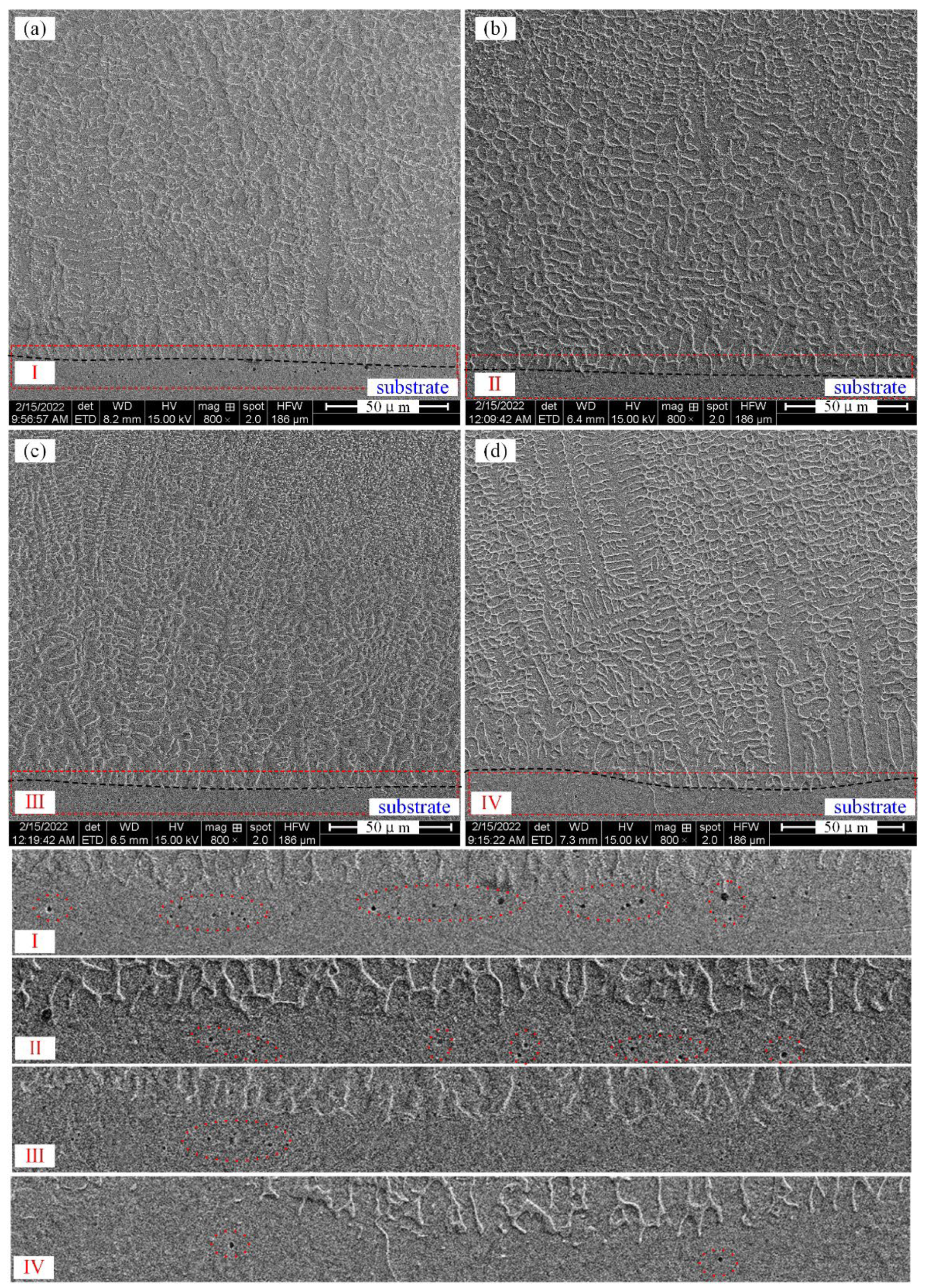
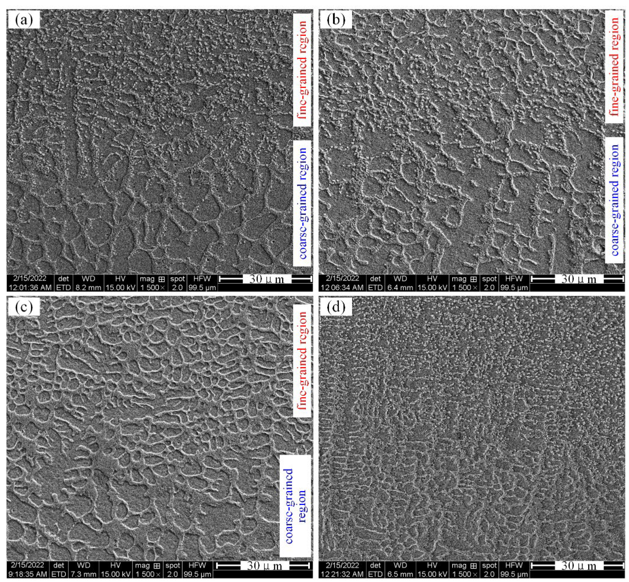
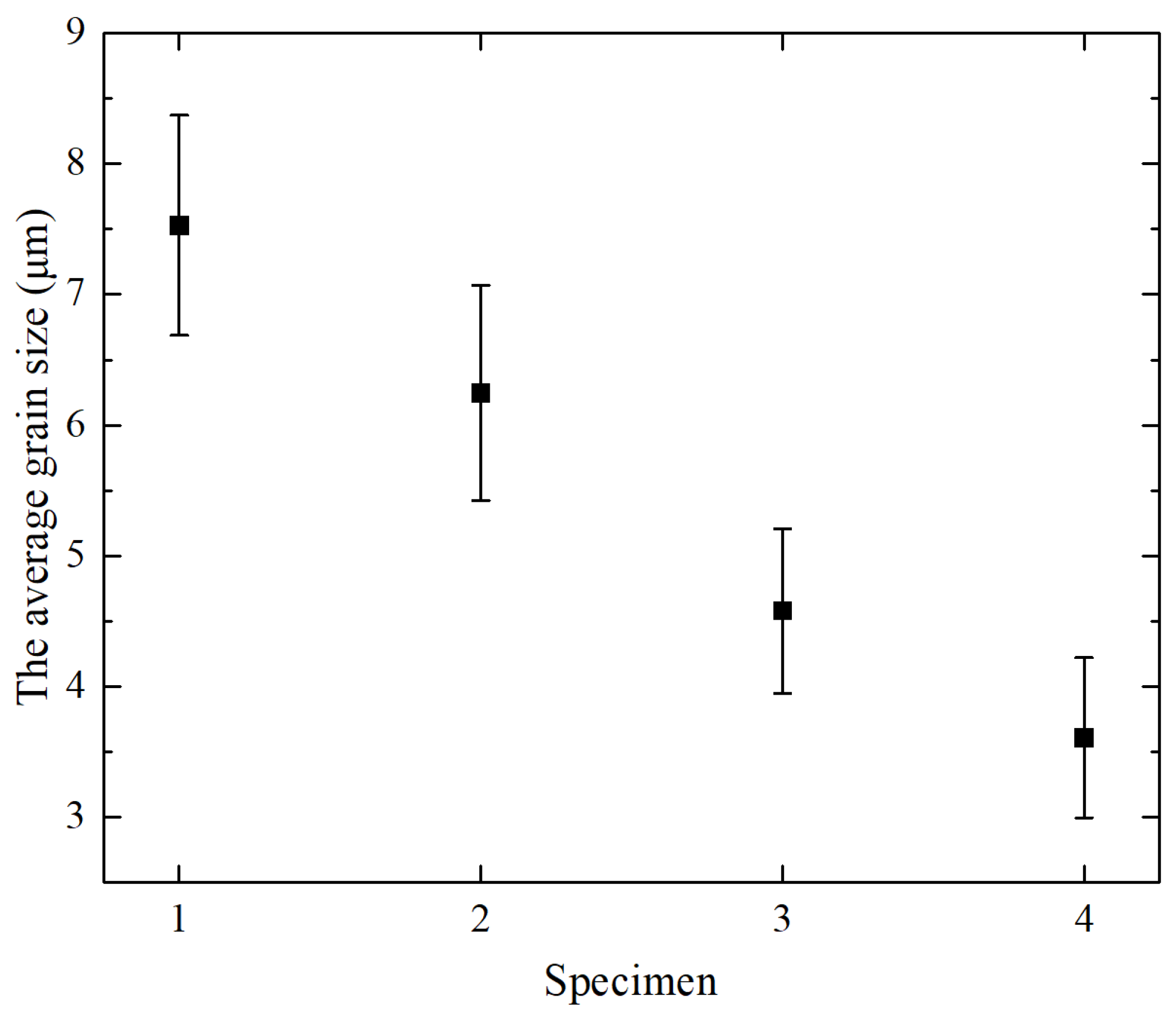
3.1. Microstructures
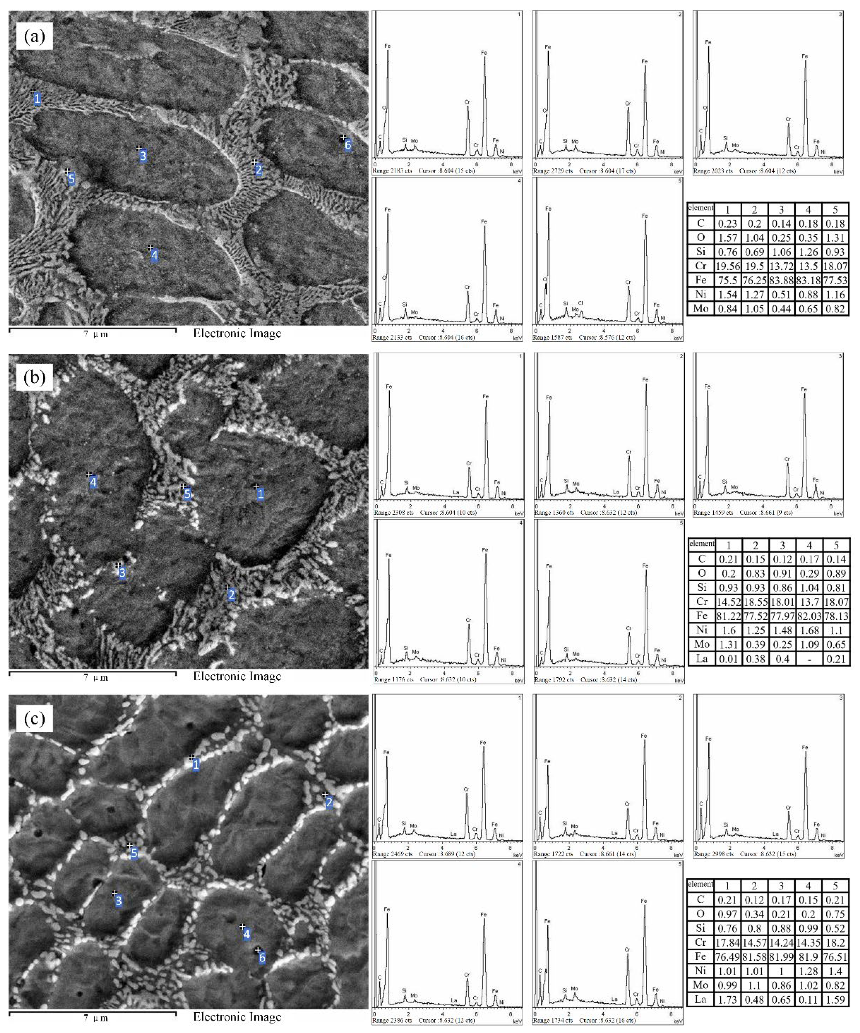
3.2. EDS Analysis
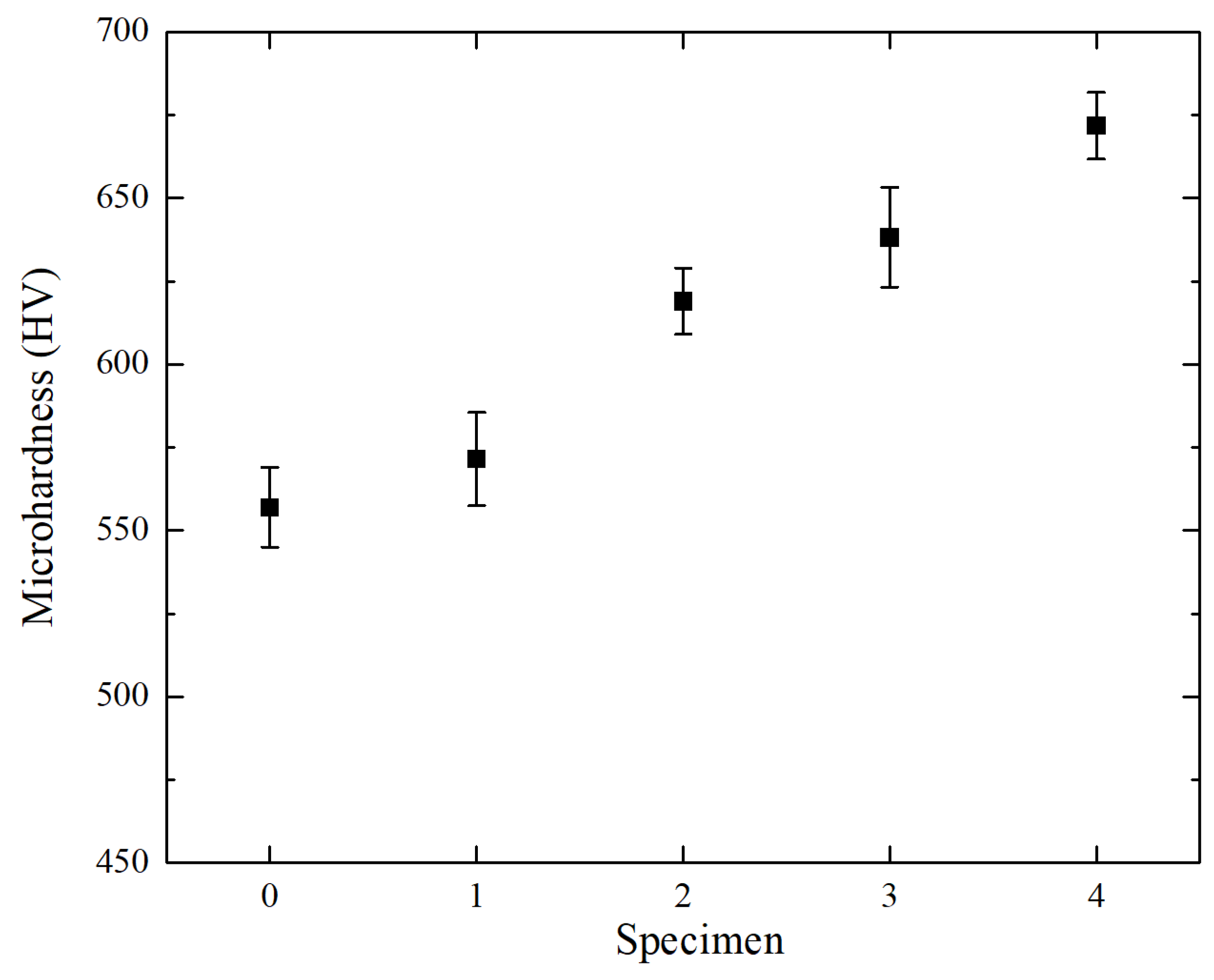
3.3. Hardness
3.4. Friction and Wear Properties Characterization
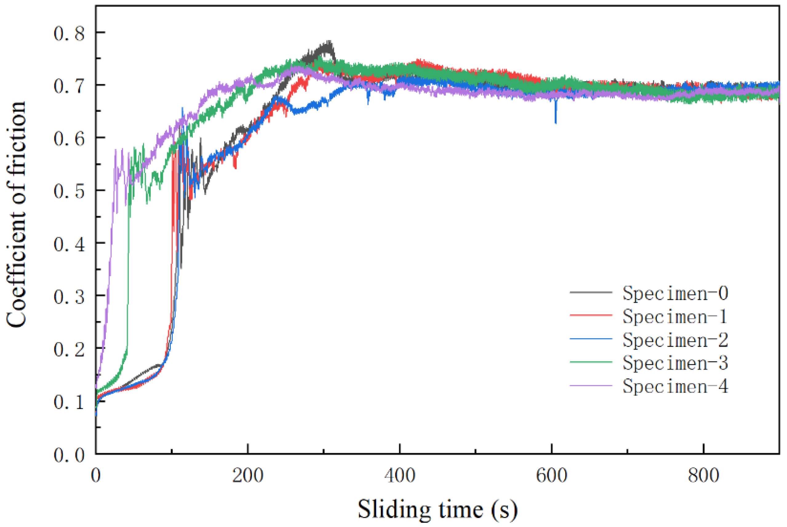
3.4.1. Coefficient of Friction
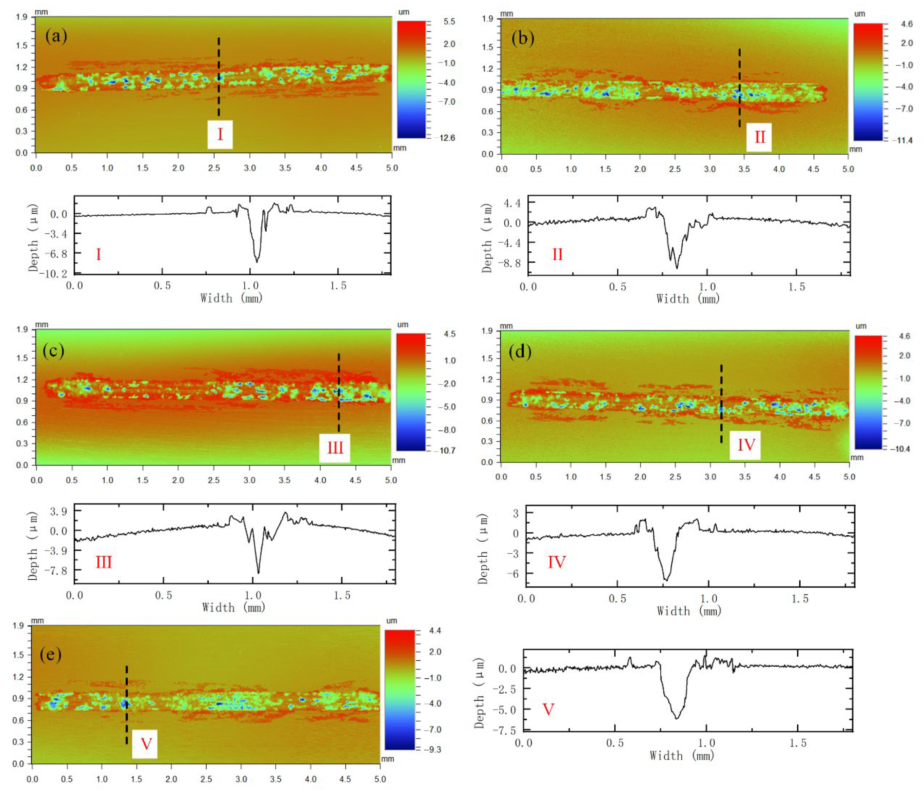
3.4.2. Wear Scar Profile and Wear Rate
3.4.3. Wear Mechanism
4. Conclusions
- (1)
- By adding La2O3, the microstructure of AM alloy becomes more uniform and the grains are significantly refined. La element is the main cause of grain refinement. La element easily reacts with other elements to form some stable compounds during the laser additive process. It can perform slag formation and reduce the content of alloy inclusions. In addition, some of the compounds formed and the La2O3 themselves can be used as nuclei for heterogeneous nucleation. Grain refinement is further promoted.
- (2)
- The running-in period is significantly shortened after adding La2O3. The coefficient of friction is reduced. The wear rate has dropped significantly. This shows that the wear reduction and wear resistance of AM alloys have been improved. The increase in the strength and toughness of the alloy caused by grain refinement after the addition of La2O3 is the main reason for the improvement of the wear resistance of the AM alloy.
- (3)
- The wear form of AM alloys after adding rare earth oxide becomes abrasive wear, accompanied by the spalling of hard particles. This is mainly due to the grain refinement strengthening effect after adding rare earth oxide.
Author Contributions
Funding
Data Availability Statement
Conflicts of Interest
References
- Karabulut, Y.; Tascioglu, E.; Kaynak, Y. Heat treatment temperature-induced microstructure, microhardness and wear resistance of Inconel 718 produced by selective laser melting additive manufacturing. Optik 2021, 227, 163907. [Google Scholar] [CrossRef]
- Bermingham, M.J.; McDonald, S.D.; Dargusch, M.S. Effect of trace lanthanum hexaboride and boron additions on microstructure, tensile properties and anisotropy of Ti-6Al-4V produced by additive manufacturing. Mater. Sci. Eng. A 2018, 719, 1–11. [Google Scholar] [CrossRef]
- Lu, B.W.; Cui, X.F.; Ma, W.Y.; Dong, M.L.; Fang, Y.C.; Wen, X.; Guo, J.; Zeng, D.C. Promoting the heterogeneous nucleation and the functional properties of directed energy deposited NiTi alloy by addition of La2O3. Addit. Manuf. 2020, 33, 101150. [Google Scholar] [CrossRef]
- Chen, F.R.; Yang, Y.H.; Chen, C.; Wang, Q.X.; Xie, R.J. Effect of La2O3 particle size on the microstructure and properties of Al Si alloys deposited via wire arc additive manufacturing. J. Manuf. Processes 2021, 68, 523–533. [Google Scholar] [CrossRef]
- Aboulkhair, N.T.; Simonelli, M.; Parry, L.; Ashcroft, I.; Tuck, C.; Hague, R. 3D printing of Aluminium alloys: Additive Manufacturing of Aluminium alloys using selective laser melting. Prog. Mater. Sci. 2019, 106, 100578. [Google Scholar] [CrossRef]
- Hassanin, H.; Zweiri, Y.; Finet, L.; Essa, K.; Qiu, C.; Attallah, M. Laser powder bed fusion of Ti-6Al-2Sn-4Zr-6Mo alloy and properties prediction using deep learning approaches. Materials 2021, 14, 2056. [Google Scholar] [CrossRef]
- Yang, N. Effect of V Element on Microstructure and Properties of TC4 Alloy Fabricated by Laser Additive. Master’s Thesis, Shenyang University of Technology, Shenyang, China, 24 May 2021. [Google Scholar]
- Qin, X.K. Study on Selective Laser Melting Forming and Property Control of Rich Zn Aluminum Alloy. Master’s Thesis, Harbin Institute of Technology, Haerbin, China, June 2021. [Google Scholar]
- Sun, N. Study on Composite Strengthening Mechanism and Properties of Inconel 625 Alloy Based on Laser Melting Deposition. Master’s Thesis, Tianjin Polytechnic University, Tianjin, China, 17 December 2020. [Google Scholar]
- Hong, C.; Gu, D.D.; Dai, D.H.; Alkhayat, M.; Urban, W.; Yuan, P.P.; Cao, S.N.; Gasser, A.; Weisheit, A.; Kelbassa, I.; et al. Laser additive manufacturing of ultrafine TiC particle reinforced Inconel 625 based composite parts: Tailored microstructures and enhanced performance. Mater. Sci. Eng. A 2015, 635, 118–128. [Google Scholar] [CrossRef]
- Shen, M.Y.; Tian, X.J.; Liu, D.; Tang, H.B.; Cheng, X. Microstructure and fracture behavior of TiC particles reinforced Inconel 625 composites prepared by laser additive manufacturing. J. Alloy. Compd. 2018, 734, 188–195. [Google Scholar] [CrossRef]
- Ge, L.C.; Zhao, Z.S.; Liu, N.X.; Liang, Y.P.; Zhang, J.T.; Wang, C.S. Regulation of aluminum content on Microstructure and properties of TC4 alloy produced by laser additive. Chin. J. Lasers 2021, 48, 1–10. [Google Scholar]
- Cooper, D.E.; Blundell, N.; Maggs, S.; Gibbons, G.J. Additive layer manufacture of Inconel 625 metal matrix composites, reinforcement material evaluation. J. Mater. Process. Technol. 2013, 213, 2191–2200. [Google Scholar] [CrossRef]
- Zhao, Y.H.; Sun, J.; Li, J.F. Study on crack sensitivity and tribological characterisation of functionally gradient material multi-layer by laser cladding with powder mixture of Ni-based alloy and tungsten carbide. Surf. Sci. Eng. 2015, 9, 371–383. [Google Scholar] [CrossRef]
- Gao, Z.N.; Bu, H.C.; Feng, Y.; Lyu, F.Y.; Zhan, X.H. Strengthening mechanism of Y2O3 nanoparticles on microstructure and mechanical properties of the laser additive manufacturing joint for large thickness TC4 titanium alloy. J. Manuf. Processes 2021, 71, 37–55. [Google Scholar] [CrossRef]
- Wang, C.L.; Gao, Y.; Zhang, Y.G. Effect of CeO2 on Microstructure and corrosion resistance of Ni60 Alloy layer made by laser cladding additive on aluminum alloy surface. Rare Met. Mater. Eng. 2017, 46, 2306–2312. [Google Scholar]
- Gu, D.D.; Zhang, H.; Liu, G.; Yang, B.Q. Control of laser additive manufacturing process of rare earth modified high strength aluminum micro truss. Acta Aeronaut. Astronaut. Sin. 2021, 42, 454–466. [Google Scholar]
- Zhang, H.; Gu, D.D.; Yang, J.K.; Dai, D.H.; Zhao, T.; Hong, C.; Gasser, A.; Poprawe, R. Selective laser melting of rare earth element Sc modified aluminum alloy: Thermodynamics of precipitation behavior and its influence on mechanical properties. Addit. Manuf. 2018, 23, 1–12. [Google Scholar] [CrossRef]
- Yang, Y.W.; Yang, M.L.; He, C.X.; Qi, F.W.; Wang, D.; Peng, S.P.; Shuai, C.J. Rare earth improves strength and creep resistance of additively manufactured Zn implants. Compos. Part B Eng. 2021, 216, 108882. [Google Scholar] [CrossRef]
- Banoth, S.; Palleda, T.N.; Shimazu, S.; Kakehi, K. Yttrium’s Effect on the Hot Cracking and Creep Properties of a Ni-Based Superalloy Built Up by Additive Manufacturing. Materials 2021, 14, 1143. [Google Scholar] [CrossRef]
- Wang, X.; Zhang, L.J.; Ning, J.; Li, S.; Na, S.J. Effect of addition of micron-sized lanthanum oxide particles on morphologies, microstructures and properties of the wire laser additively manufactured Ti–6Al–4V alloy. Mater. Sci. Eng. A 2021, 803, 140475. [Google Scholar] [CrossRef]
- Wang, Q.; Zhang, K.; Qiu, D.; Niu, W.J. Additive manufacturing of high-strength commercially pure titanium through lanthanum oxide addition. Mater. Charact. 2021, 176, 111074. [Google Scholar] [CrossRef]
- Lu, B.W.; Cui, X.F.; Jin, G.; Dong, M.L.; Fang, Y.C.; Wen, X.; Ma, W.Y. Effect of La2O3 addition on mechanical properties and wear behaviour of NiTi alloy fabricated by direct metal deposition. Opt. Laser Technol. 2020, 129, 106290. [Google Scholar] [CrossRef]
- Shi, Y.M.; Li, J.B.; Zhang, J.; Wen, B.Q.; Li, L.Q.; Wang, X.F.; Ren, S.X. Effect of La2O3 addition on wear properties of Ni60a/SiC coating using laser-cladding. Opt. Laser Technol. 2022, 148, 107640. [Google Scholar] [CrossRef]
- Zhao, N.; Tao, L.; Guo, H.; Zhang, M.Q. Microstructure and Wear Resistance of Laser Cladded Ni-based Coatings with Nanometer La2O3 Addition. Rare Met. Mater. Eng. 2017, 46, 2092–2096. [Google Scholar]
- Zhang, Z.Y.; Wang, Z.P.; Liang, B.N. Microstructure and Dry-Sliding Wear Behavior of Thermal Sprayed and Fused Ni-Based Coatings with the Addition of La2O3. Tribol. Lett. 2010, 37, 141–148. [Google Scholar] [CrossRef]
- Zhao, Y.H.; Sun, J.; Li, J.F. Study on microstructure, properties, wear resistance and corrosion resistance of laser cladding FeCr alloy repair layer of KMN steel. J. Mech. Eng. 2015, 51, 37–43. [Google Scholar] [CrossRef]
- Kainuma, R.; Takahashi, S.; Ishida, K. Thermoelastic martensite and shape memory effect in ductile Cu-Al-Mn alloys. Metall. Mater. Trans. A 1996, 27, 2187–2195. [Google Scholar] [CrossRef]
- Zhao, Y.H. Research on Laser Cladding Repaired and Subsequent Processing Characteristics of KMN Steel Compressor Blade. Ph.D. Thesis, Shandong Universtiy, Jinan, China, 6 April 2015. [Google Scholar]
- Lu, X.L.; Chen, F.; Li, W.S.; Zheng, Y.F. Effect of Ce addition on the microstructure and damping properties of Cu–Al–Mn shape memory alloys. J. Alloy. Compd. 2009, 480, 608–611. [Google Scholar] [CrossRef]
- Wang, K.L.; Zhang, Q.B.; Sun, M.L.; Wei, X.G. Microstructural characteristics of laser clad coatings with rare earth metal elements. J. Mater. Process. Technol. 2003, 139, 448–452. [Google Scholar] [CrossRef]
- Li, Q.A.; Yu, Z.H.; Wang, C.S.; Yu, H.; Liu, J.J.; Wang, Y. Effect of CeO2 on Microstructure and Wear Resistance of M2+4B Laser Alloying Layer. Chin. J. Rare Earth 1995, 13, 280–282. [Google Scholar]
- Wang, W.J.; Fu, Z.K.; Cao, X.; Guo, J.; Liu, Q.Y.; Zhu, M.H. The role of lanthanum oxide on wear and contact fatigue damage resistance of laser cladding Fe-based alloy coating under oil lubrication condition. Tribol. Int. 2016, 94, 470–478. [Google Scholar] [CrossRef]


| Element | C | Si | Mo | Cr | Ni | B | Fe |
|---|---|---|---|---|---|---|---|
| Compositions | 0.15 | 1.1 | 1.0 | 17.35 | 1.35 | ≤1.26 | balance |
| Scheme | Width (μm) | Depth (μm) | Wear Rate (10−4 mm3/Nm) |
|---|---|---|---|
| 0 | 452 ± 20.3 | 7.24 ± 0.32 | 3.599 ± 0.56 |
| 1 | 413 ± 28.2 | 6.65 ± 0.30 | 3.332 ± 0.41 |
| 2 | 399 ± 26.4 | 6.07 ± 0.59 | 3.051 ± 0.42 |
| 3 | 375 ± 30.2 | 5.40 ± 0.43 | 2.453 ± 0.31 |
| 4 | 372 ± 21.5 | 4.99 ± 0.38 | 2.217 ± 0.35 |
Publisher’s Note: MDPI stays neutral with regard to jurisdictional claims in published maps and institutional affiliations. |
© 2022 by the authors. Licensee MDPI, Basel, Switzerland. This article is an open access article distributed under the terms and conditions of the Creative Commons Attribution (CC BY) license (https://creativecommons.org/licenses/by/4.0/).
Share and Cite
Zhao, Y.; Meng, W.; Wang, P.; Du, C.; Wang, X. Effect of Lanthanum Oxide Addition on Microstructure and Wear Performance of Iron-Chromium Alloy Manufactured by Laser Direct Deposition Additive Manufacturing. Materials 2022, 15, 3234. https://doi.org/10.3390/ma15093234
Zhao Y, Meng W, Wang P, Du C, Wang X. Effect of Lanthanum Oxide Addition on Microstructure and Wear Performance of Iron-Chromium Alloy Manufactured by Laser Direct Deposition Additive Manufacturing. Materials. 2022; 15(9):3234. https://doi.org/10.3390/ma15093234
Chicago/Turabian StyleZhao, Yanhua, Wei Meng, Peifu Wang, Chuanbin Du, and Xiaowei Wang. 2022. "Effect of Lanthanum Oxide Addition on Microstructure and Wear Performance of Iron-Chromium Alloy Manufactured by Laser Direct Deposition Additive Manufacturing" Materials 15, no. 9: 3234. https://doi.org/10.3390/ma15093234