
Welding Characteristics of Laser-MIG Hybrid Welding of Arc-Welded Aluminum Profiles for High-Speed Trains


Abstract
:1. Introduction
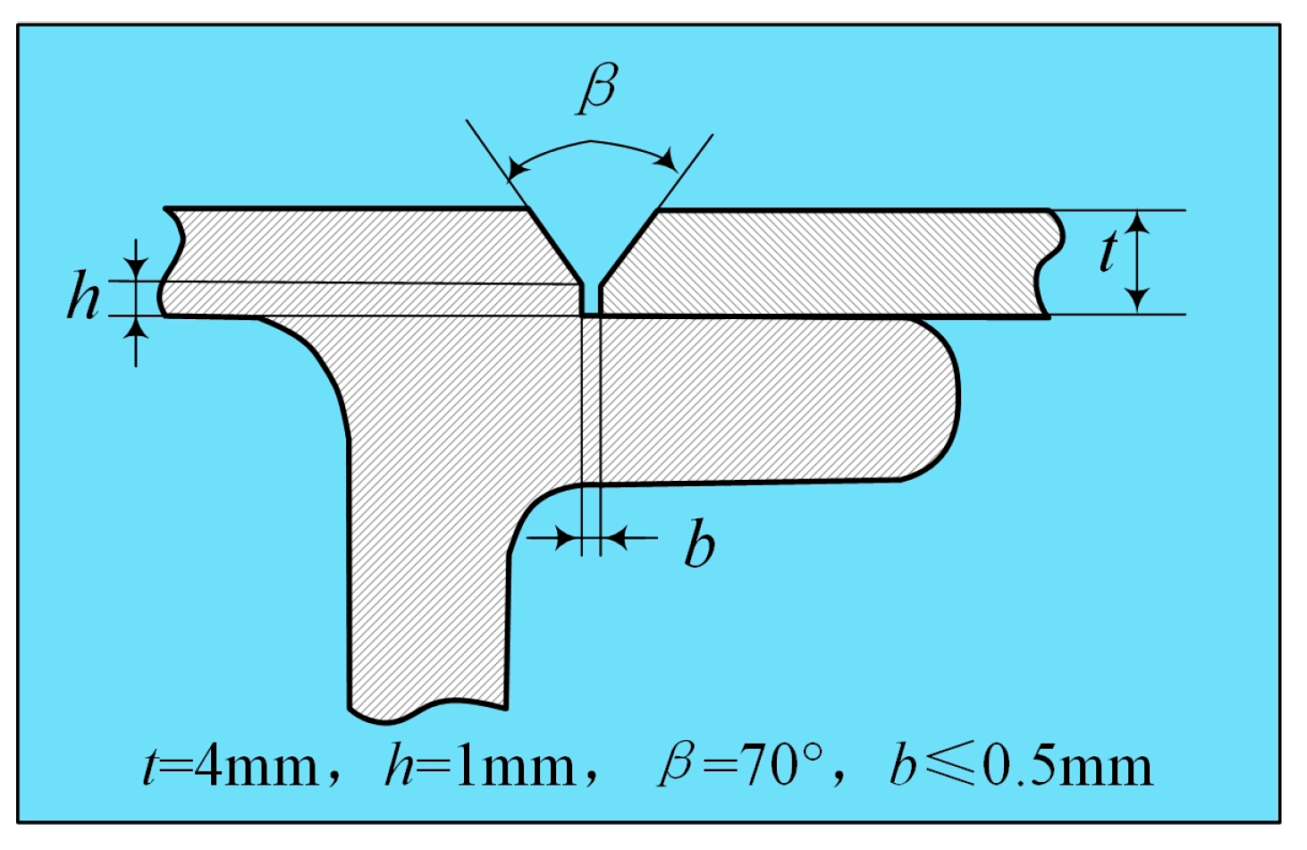
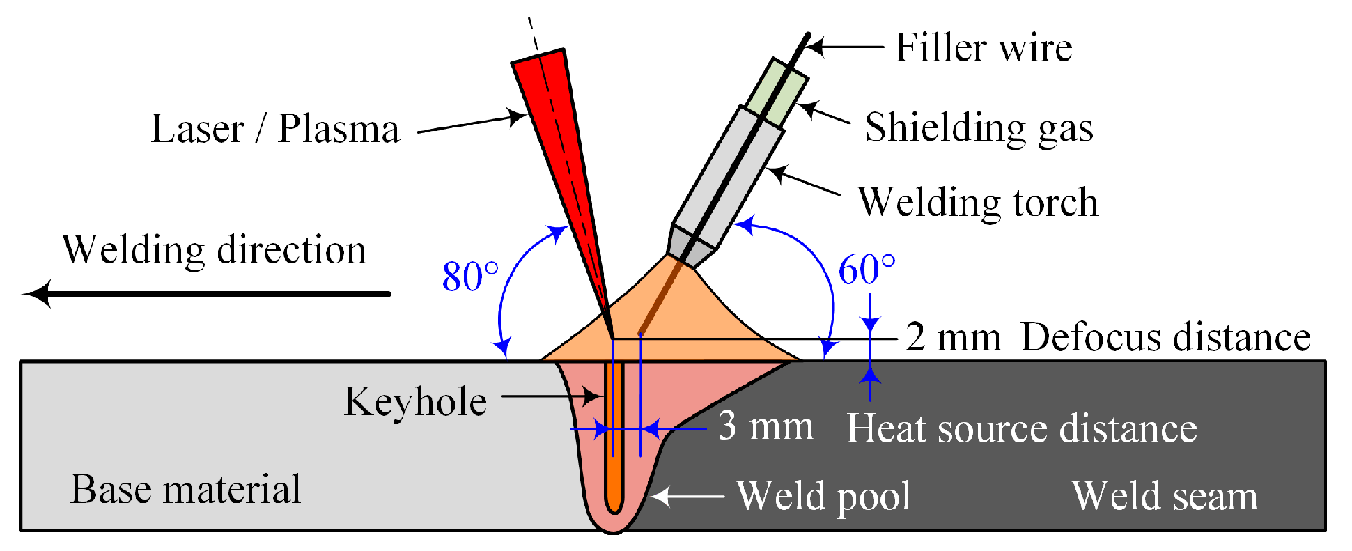
2. Materials and Methods
2.1. Materials
2.2. Methods
3. Results
3.1. Parameter Optimization
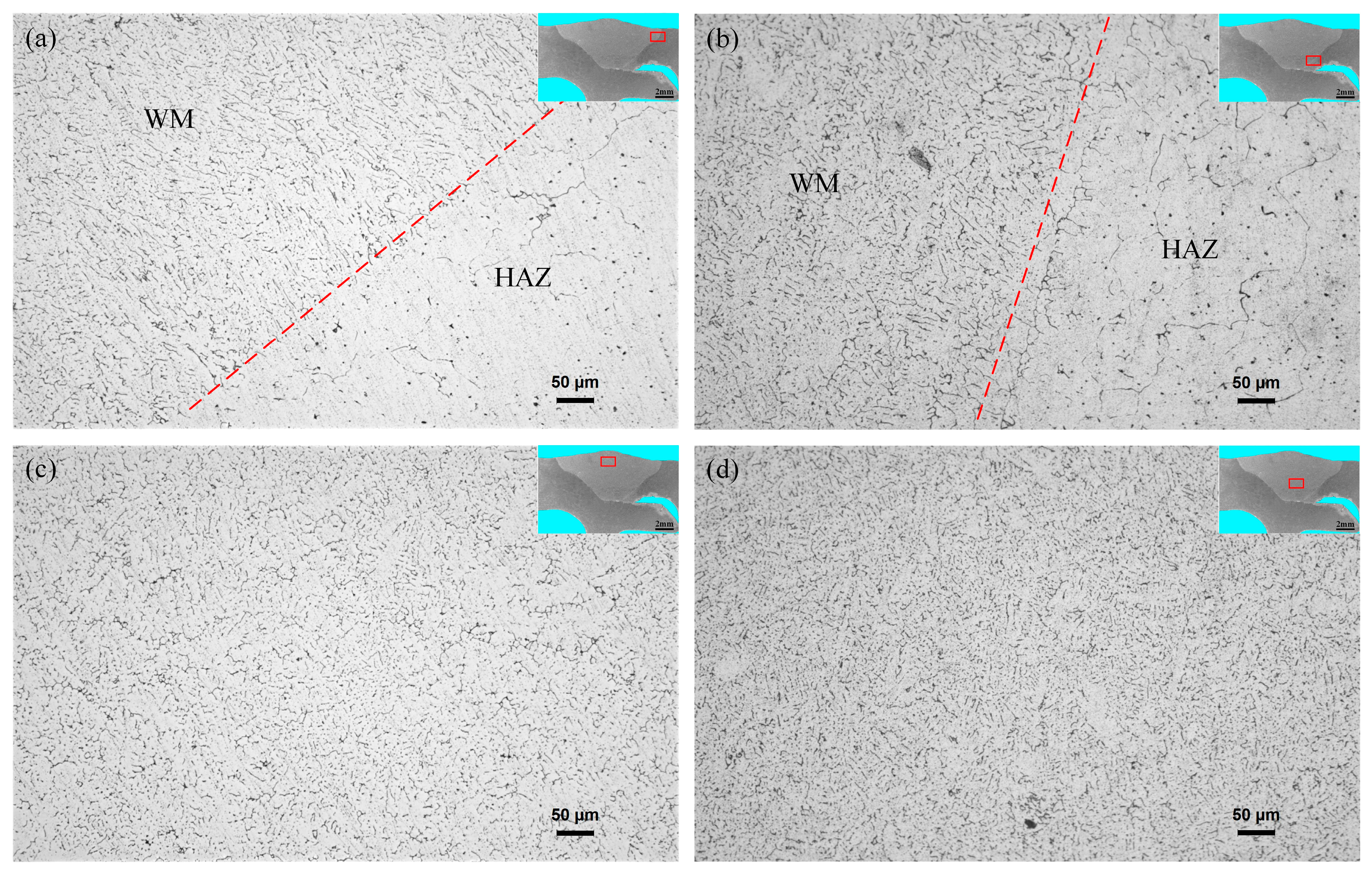
3.2. Microstructure Characteristics
3.3. Mechanical Properties
4. Conclusions
- The optimized laser-MIG hybrid welding parameters of a 4 mm thick arc-welded aluminum alloy profile were: welding speed 1.0 m/min, laser power 2.7 kW, arc current 200 A, spot diameter 0.8 mm, heat source spacing 3 mm, and defocus amount 0 mm. Based on the orthogonal test, the order of influence on the tensile strength of the joint was arc current > laser power > defocus amount.
- The microstructure of the joint weld center was a typical dendrite structure, and the grain size of the arc-affected zone was larger than that of the laser-affected zone; the columnar crystal structure was near the fusion line, and the grains in the heat-affected zone were slightly coarse. The heat-affected zone had an obvious softening phenomenon, which was the lowest hardness area of the joint.
- The average tensile strength of the joint reached up to 212 MPa, which was about 86% of the base metal. The sample fractured in the softening zone of the heat-affected zone, and the fracture showed typical plastic fracture characteristics. Bending specimens by 180° root bend and face bend results in a stretching, smooth, crack-free surface.
- The test results show that laser-MIG hybrid welding had good applicability and feasibility in high-speed train arc-welded aluminum alloy profile manufacturing.
Author Contributions
Funding
Institutional Review Board Statement
Informed Consent Statement
Data Availability Statement
Conflicts of Interest
References
- Zhang, L.; He, H.; Li, S.; Wu, X.; Li, L. Dynamic compression behavior of 6005 aluminum alloy aged at elevated temperatures. Vacuum 2018, 155, 604–611. [Google Scholar] [CrossRef]
- Zhang, M.X.; Wang, C.; Zhang, S.Y.; Liu, X.; Wang, X.; Ren, M.W.; Wang, H.Y. Enhanced aging precipitation behavior and mechanical properties of 6022 Al-Mg-Si alloy with Zr addition. Mater. Sci. Eng. A 2022, 840, 142957. [Google Scholar] [CrossRef]
- Liu, S.; Li, J.; Mi, G.; Wang, C.; Hu, X. Study on laser-MIG hybrid welding characteristics of A7N01-T6 aluminum alloy. Int. J. Adv. Manuf. Technol. 2016, 87, 1135–1144. [Google Scholar] [CrossRef]
- Jing, H.; Ye, X.; Hou, X.; Qian, X.; Zhang, P.; Yu, Z.; Wu, D.; Fu, K. Effect of weld pool flow and keyhole formation on weld penetration in laser-MIG hybrid welding within a sensitive laser power range. Appl. Sci. 2022, 12, 4100. [Google Scholar] [CrossRef]
- Leo, P.; Renna, G.; Casalino, G.; Olabi, A.G. Effect of power distribution on the weld quality during hybrid laser welding of an Al-Mg alloy. Opt. Laser Technol. 2015, 73, 118–126. [Google Scholar] [CrossRef]
- Miao, H.; Yu, G.; He, X.; Li, S.; Chen, X. Comparative study of hybrid laser-MIG leading configuration on porosity in aluminum alloy bead-on-plate welding. Int. J. Adv. Manuf. Technol. 2017, 91, 2681–2688. [Google Scholar] [CrossRef] [Green Version]
- Yürük, A.; Çevik, B.; Kahraman, N. Analysis of mechanical and microstructural properties of gas metal arc welded dissimilar aluminum alloys (AA5754/AA6013). Mater. Chem. Phys. 2021, 273, 125117. [Google Scholar]
- Sakthivel, P.; Manobbala, V.; Manikandan, T.; Mohammed Arman Salik, Z.; Rajkamal, G. Investigation on mechanical properties of dissimilar metals using MIG welding. Mater. Today Proc. 2021, 37, 531–536. [Google Scholar] [CrossRef]
- Baskutis, S.; Baskutiene, J.; Bendikiene, R.; Ciuplys, A.; Dutkus, K. Comparative research of microstructure and mechanical properties of stainless and structural steel dissimilar welds. Materials 2021, 14, 6180. [Google Scholar] [CrossRef]
- Li, Y.; Yang, S.; Peng, Z.; Wang, Z.; Gao, Z. Microstructure, fatigue properties and stress concentration analysis of 6005 aluminum alloy MIG welded lap joint. Materials 2022, 15, 7729. [Google Scholar] [CrossRef]
- Oliveira, J.P.; Crispim, B.; Zeng, Z.; Omori, T.; Braz Fernandes, F.M.; Miranda, R.M. Microstructure and mechanical properties of gas tungsten arc welded Cu-Al-Mn shape memory alloy rods. J. Mater. Process. Technol. 2019, 271, 93–100. [Google Scholar] [CrossRef]
- Xin, Z.; Yang, Z.; Zhao, H.; Chen, Y. Comparative study on welding characteristics of laser-CMT and plasma-CMT hybrid welded AA6082-T6 aluminum alloy butt joints. Materials 2019, 12, 3300. [Google Scholar] [CrossRef] [Green Version]
- Kim, Y.P.; Alam, N.; Bang, H.S.; Bang, H.S. Observation of hybrid (cw Nd: YAG laser plus MIG) welding phenomenon in AA 5083 butt joints with different gap condition. Sci. Technol. Weld. Join. 2006, 11, 295–307. [Google Scholar] [CrossRef]
- Lee, C.-M.; Woo, W.-S.; Baek, J.-T.; Kim, E.-J. Laser and arc manufacturing processes: A review. Int. J. Precis. Eng. Manuf. 2016, 17, 973–985. [Google Scholar] [CrossRef]
- Wang, J.; Nishimura, P.; Fujii, K.; Katayama, S.; Mizutani, M. Study of improvement of gap tolerance in laser-MIG arc hybrid welding of aluminum alloy. Weld. Int. 2008, 23, 723–733. [Google Scholar] [CrossRef]
- Li, D.; Ji, H.; Liu, Y.; Gou, G.Q.; Chen, H.; Liu, J.B.; Meng, L.C. Simulation on temperature and residual stress field of laser-MIG hybrid welding of A6N01-T5 alloy. Adv. Mater. Res. 2011, 399–401, 2040–2043. [Google Scholar] [CrossRef]
- Bunaziv, I.; Akselsen, O.M.; Salminen, A.; Unt, A. Fiber laser-MIG hybrid welding of 5 mm 5083 aluminum alloy. J. Mater. Process. Technol. 2016, 233, 107–114. [Google Scholar] [CrossRef]
- Li, X.; Wang, X.; Lei, Z.; Yang, H. Investigation on softening of welded joint of side walls of high speed train of 6N01 aluminum alloy. Trans. China Weld. Inst. 2015, 36, 95–98 + 118. (In Chinese) [Google Scholar]
- Jiang, Z.; Hua, X.; Huang, L.; Wu, D.; Li, F.; Zhang, Y. Double-sided hybrid laser-MIG welding plus MIG welding of 30-Mm-thick aluminium alloy. Int. J. Adv. Manuf. Technol. 2018, 97, 903–913. [Google Scholar] [CrossRef]
- Cornacchia, G.; Cecchel, S.; Panvini, A. A comparative study of mechanical properties of metal inert gas (MIG)-cold metal transfer (CMT) and fiber laser-MIG hybrid welds for 6005A T6 extruded sheet. Int. J. Adv. Manuf. Technol. 2018, 94, 2017–2030. [Google Scholar] [CrossRef]
- Huang, L.; Wu, D.; Hua, X.; Liu, S.; Jiang, Z.; Li, F.; Wang, H.; Shi, S. Effect of the welding direction on the microstructural characterization in fiber laser-GMAW hybrid welding of 5083 aluminum alloy. J. Manuf. Process. 2018, 31, 514–522. [Google Scholar] [CrossRef]
- Wang, X.; Li, B.; Li, M.; Huang, C.; Chen, H. Study of local-zone microstructure, strength and fracture toughness of hybrid laser-metal-inert-gas-welded A7N01 aluminum alloy joint. Mater. Sci. Eng. A 2017, 688, 114–122. [Google Scholar] [CrossRef]
- Zhan, X.; Zhao, Y.; Liu, Z.; Gao, Q.; Bu, H. Microstructure and porosity characteristics of 5A06 aluminum alloy joints using laser-MIG hybrid welding. J. Manuf. Process. 2018, 35, 437–445. [Google Scholar] [CrossRef]
- Wang, Q.; Chen, H.; Zhu, Z.; Qiu, P.; Cui, Y. A characterization of microstructure and mechanical properties of A6N01S-T5 aluminum alloy hybrid fiber laser-MIG welded joint. Int. J. Adv. Manuf. Technol. 2016, 86, 1375–1384. [Google Scholar] [CrossRef]
- Li, F.; Feng, S.; Li, M.; Zhu, Y. Softening phenomenon of heat-affected zone in laser welding of 6082 Al alloys with filler wire. Chin. J. Lasers 2018, 45, 1102007. [Google Scholar]
- Han, X.H.; Yang, Z.B.; Ma, Y.; Shi, C.Y.; Xin, Z.B. Comparative study of laser-arc hybrid welding for AA6082-T6 aluminum alloy with two different arc modes. Metals 2020, 10, 407. [Google Scholar] [CrossRef]


| Material | Si | Fe | Cu | Mn | Mg | Cr | Zn | Ti | Al |
|---|---|---|---|---|---|---|---|---|---|
| A6N01S-T5 | 0.4~0.9 | ≤0.35 | ≤0.35 | ≤0.3 | 0.4~0.8 | ≤0.3 | ≤0.25 | ≤0.35 | Bal. |
| ER5356 | 0.13 | 0.12 | 0.01 | 0.06 | 4.90 | 0.07 | 0.12 | 0.11 | Bal. |
| Level | Factor | ||
|---|---|---|---|
| A/kW | B/A | C/mm | |
| 1 | 2.5 | 200 | 0 |
| 2 | 2.3 | 190 | −2 |
| 3 | 2.7 | 210 | +2 |
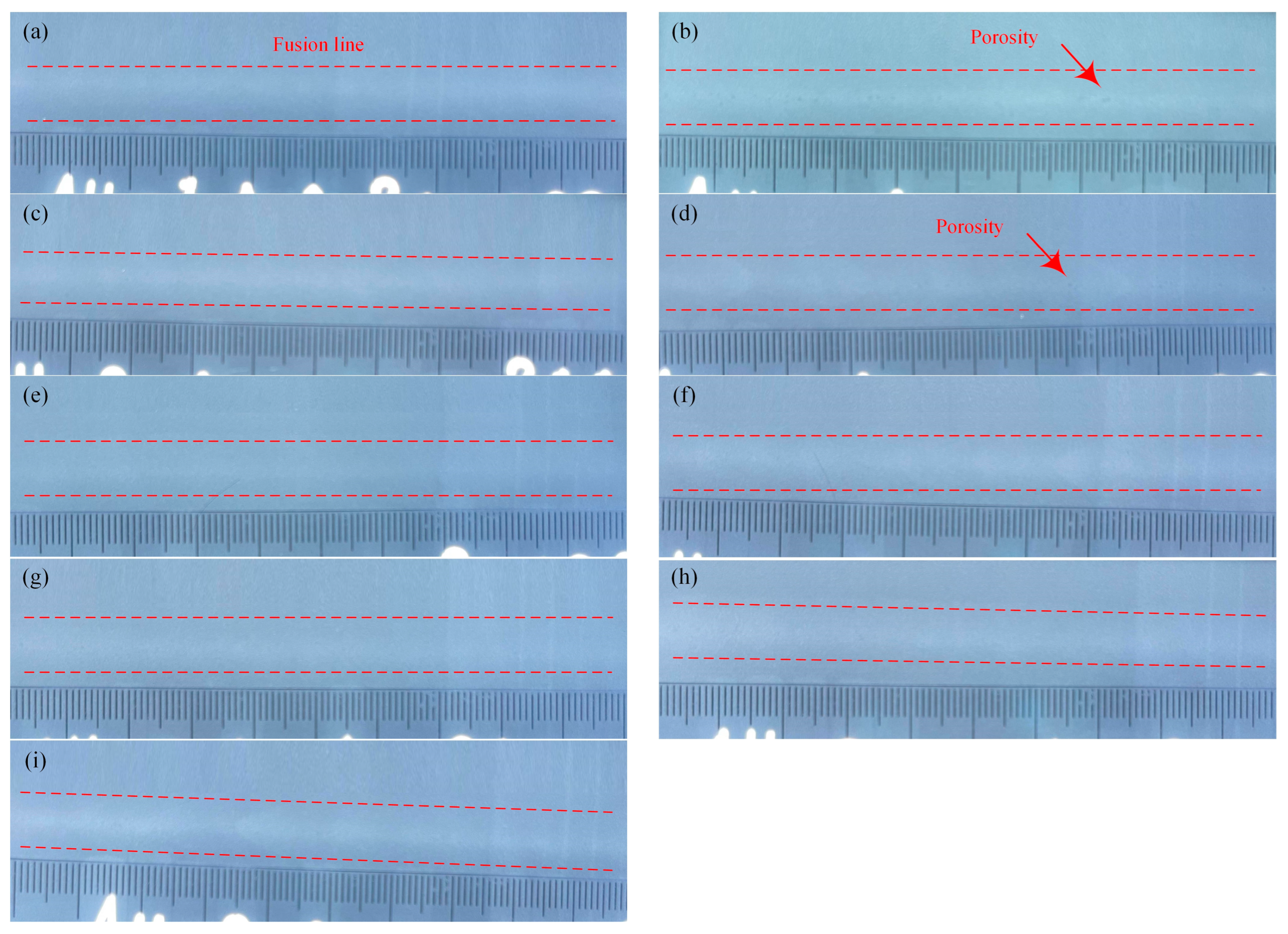
| No. | Laser Power /kW | Arc Current /A | Defocusing Amount /mm | Surface | Cross-Section | Tensile Strength /MPa |
|---|---|---|---|---|---|---|
| 1# | 2.5 | 200 | 0 |  |  | 196 |
| 2# | 2.5 | 190 | −2 |  | 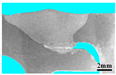 | 165 |
| 3# | 2.5 | 210 | 2 | 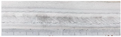 | 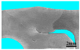 | 173 |
| 4# | 2.3 | 200 | −2 | 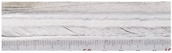 | 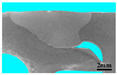 | 195 |
| 5# | 2.3 | 190 | 2 | 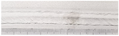 | 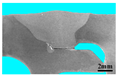 | 172 |
| 6# | 2.3 | 210 | 0 | 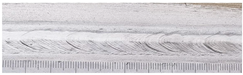 | 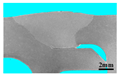 | 182 |
| 7# | 2.7 | 200 | 2 | 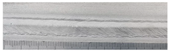 | 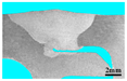 | 199 |
| 8# | 2.7 | 190 | 0 |  | 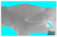 | 182 |
| 9# | 2.7 | 210 | −2 | 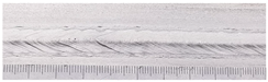 |  | 193 |
| K1 | 177.7 | 196.7 | 186.3 | |||
| K2 | 182.8 | 172.8 | 184.2 | |||
| K3 | 191.4 | 182.4 | 181.4 | |||
| R | 13.6 | 23.8 | 4.8 | |||
| Priorities | B > A > C | |||||
| Optimization | A3 | B1 | C1 | |||
| No. | Tensile Strength/MPa | Joint Efficiency/% | Fracture Location | ||
|---|---|---|---|---|---|
| Sample | Average | ||||
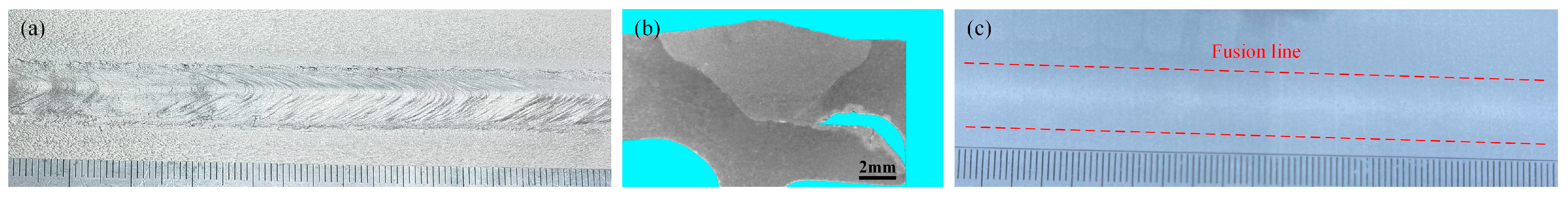
| LS-1# | 217 | 212 | 86 | HAZ | 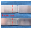 |
| LS-2# | 207 | ||||
| No. | Sample Size/mm | Bending Angle 180°, Indenter Diameter 20 mm | Note | |
|---|---|---|---|---|
| WQ-1# | 300 × 25 × 3 | no crack | Face bend |  |
| WQ-2# | 300 × 25 × 3 | no crack | ||
| WQ-3# | 300 × 25 × 3 | no crack | Root bend |  |
| WQ-4# | 300 × 25 × 3 | no crack | ||
Disclaimer/Publisher’s Note: The statements, opinions and data contained in all publications are solely those of the individual author(s) and contributor(s) and not of MDPI and/or the editor(s). MDPI and/or the editor(s) disclaim responsibility for any injury to people or property resulting from any ideas, methods, instructions or products referred to in the content. |
© 2023 by the authors. Licensee MDPI, Basel, Switzerland. This article is an open access article distributed under the terms and conditions of the Creative Commons Attribution (CC BY) license (https://creativecommons.org/licenses/by/4.0/).
Share and Cite
Du, L.; Yang, Z.; Wang, X. Welding Characteristics of Laser-MIG Hybrid Welding of Arc-Welded Aluminum Profiles for High-Speed Trains. Materials 2023, 16, 404. https://doi.org/10.3390/ma16010404
Du L, Yang Z, Wang X. Welding Characteristics of Laser-MIG Hybrid Welding of Arc-Welded Aluminum Profiles for High-Speed Trains. Materials. 2023; 16(1):404. https://doi.org/10.3390/ma16010404
Chicago/Turabian StyleDu, Lingzhi, Zhibin Yang, and Xing Wang. 2023. "Welding Characteristics of Laser-MIG Hybrid Welding of Arc-Welded Aluminum Profiles for High-Speed Trains" Materials 16, no. 1: 404. https://doi.org/10.3390/ma16010404
APA StyleDu, L., Yang, Z., & Wang, X. (2023). Welding Characteristics of Laser-MIG Hybrid Welding of Arc-Welded Aluminum Profiles for High-Speed Trains. Materials, 16(1), 404. https://doi.org/10.3390/ma16010404