
Formation Mechanism of Thicker Intermetallic Compounds in Friction Stir Weld Joints of Dissimilar AA2024/AZ31B Alloys

Abstract
:1. Introduction
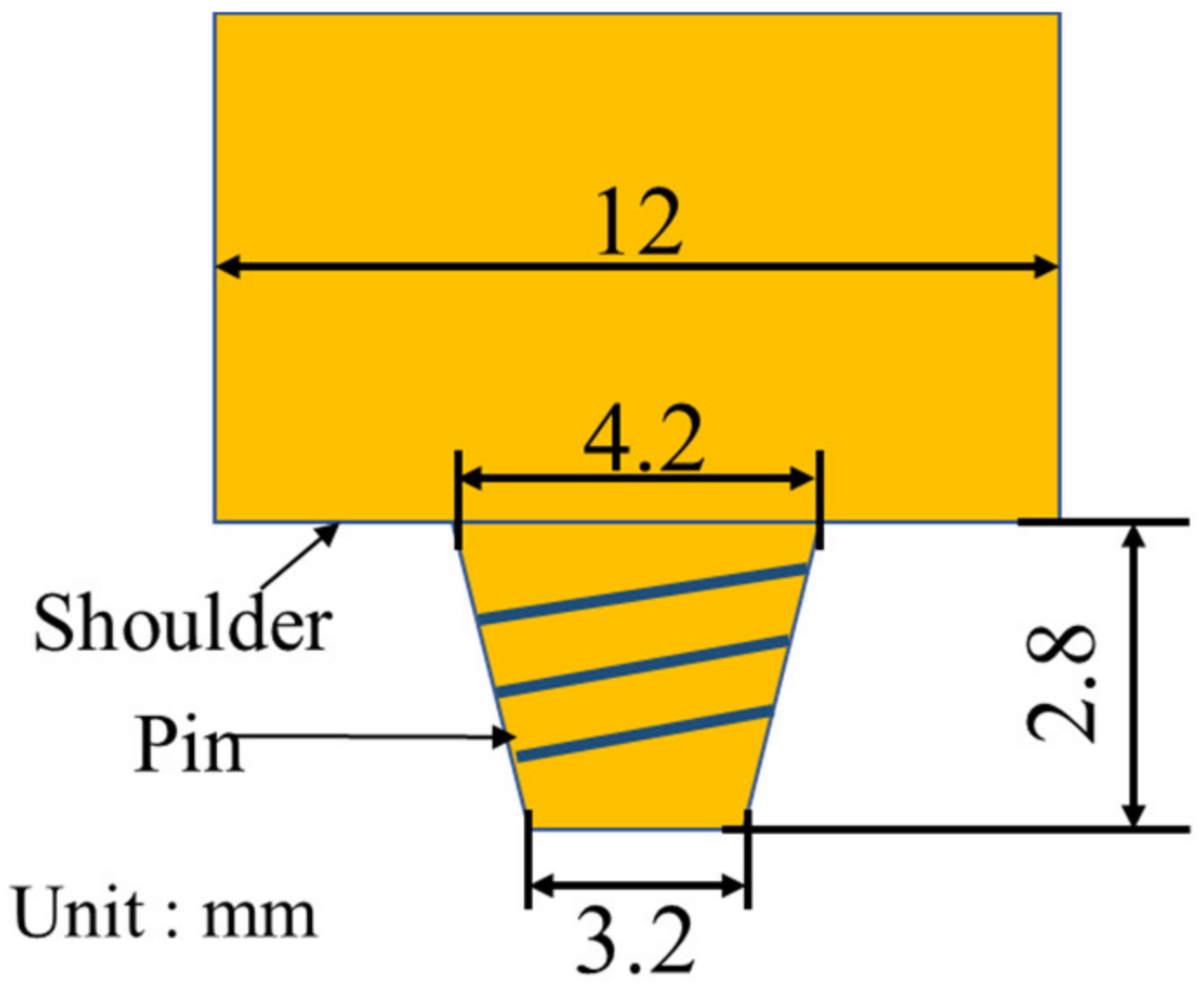
2. Experimental
3. Results and Discussion
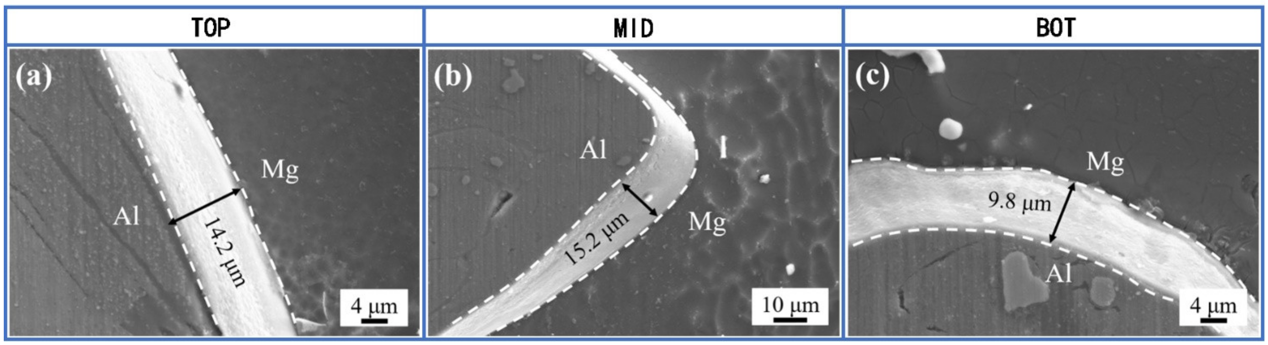
3.1. SEM Images of IMCs
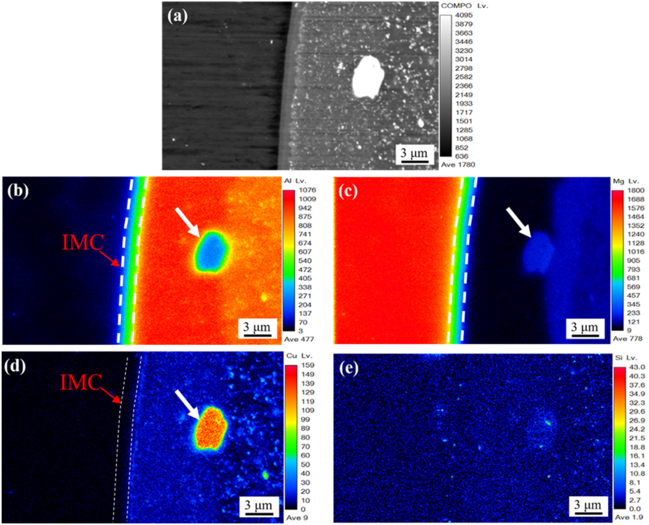
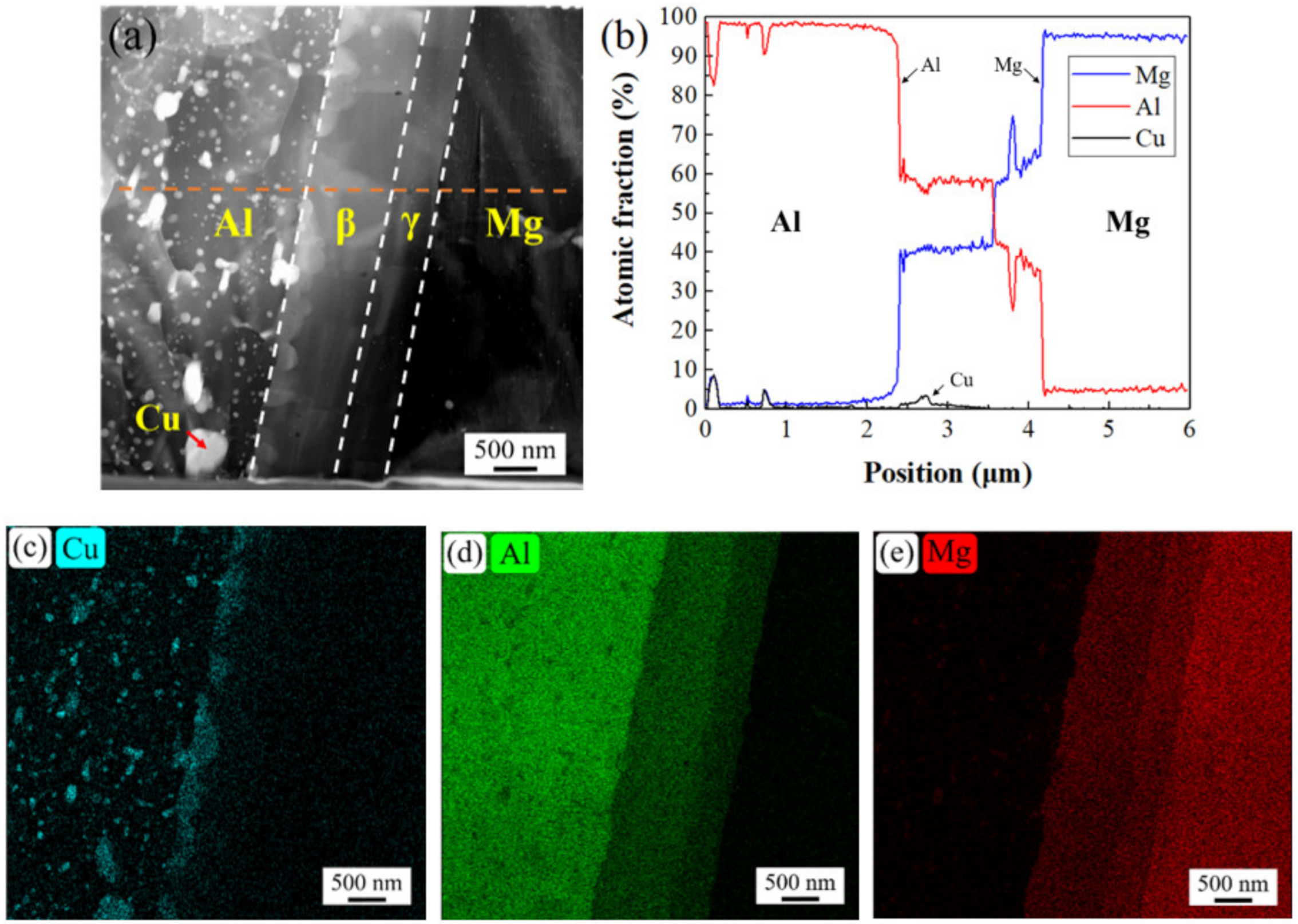
3.2. Bonding Interface
3.3. Formation Mechanism of Thicker IMCs
4. Conclusions
- (1)
- The SEM images of intermetallic compounds at the interface show that the thickness of IMCs is larger in dissimilar FSW of AA2024/AZ31B than that in dissimilar FSW of AA6061/AZ31B. Because the welding temperature in AA2024/AZ31B FSW is very close to that in AA6061/AZ31B FSW under the same conditions, it is clear that the larger IMCs thickness in AA2024/AZ31B weld is caused by the copper content in AA2024.
- (2)
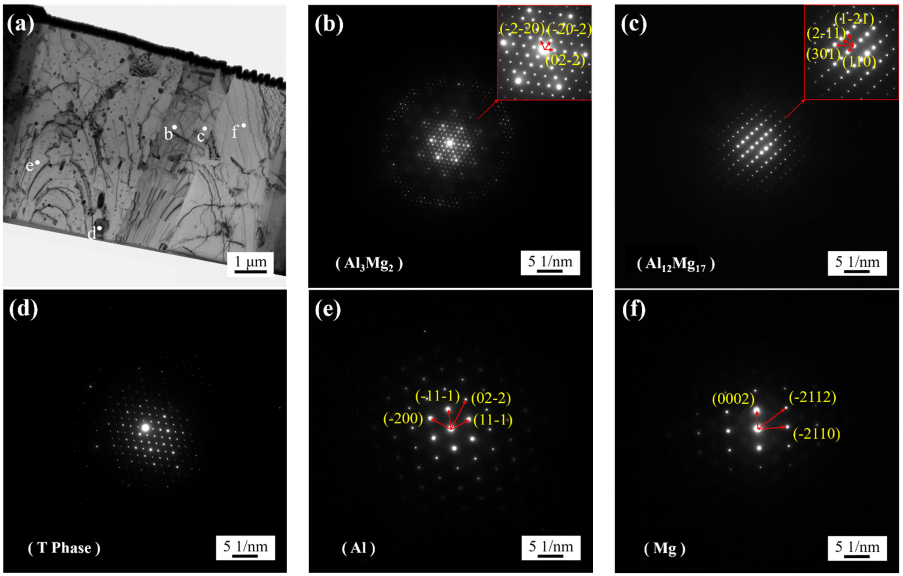
- The EPMA and STEM images show that there is an obvious gradient transition of aluminum and magnesium in intermetallic compounds, which proves that intermetallic compounds have a double-layer structure of β phase (Al3Mg2) and γ phase (Al12Mg17). Copper was aggregated between the intermetallic compound and aluminum matrix, and segregated between β phase and aluminum matrix in the form of a strengthening phase.
- (3)
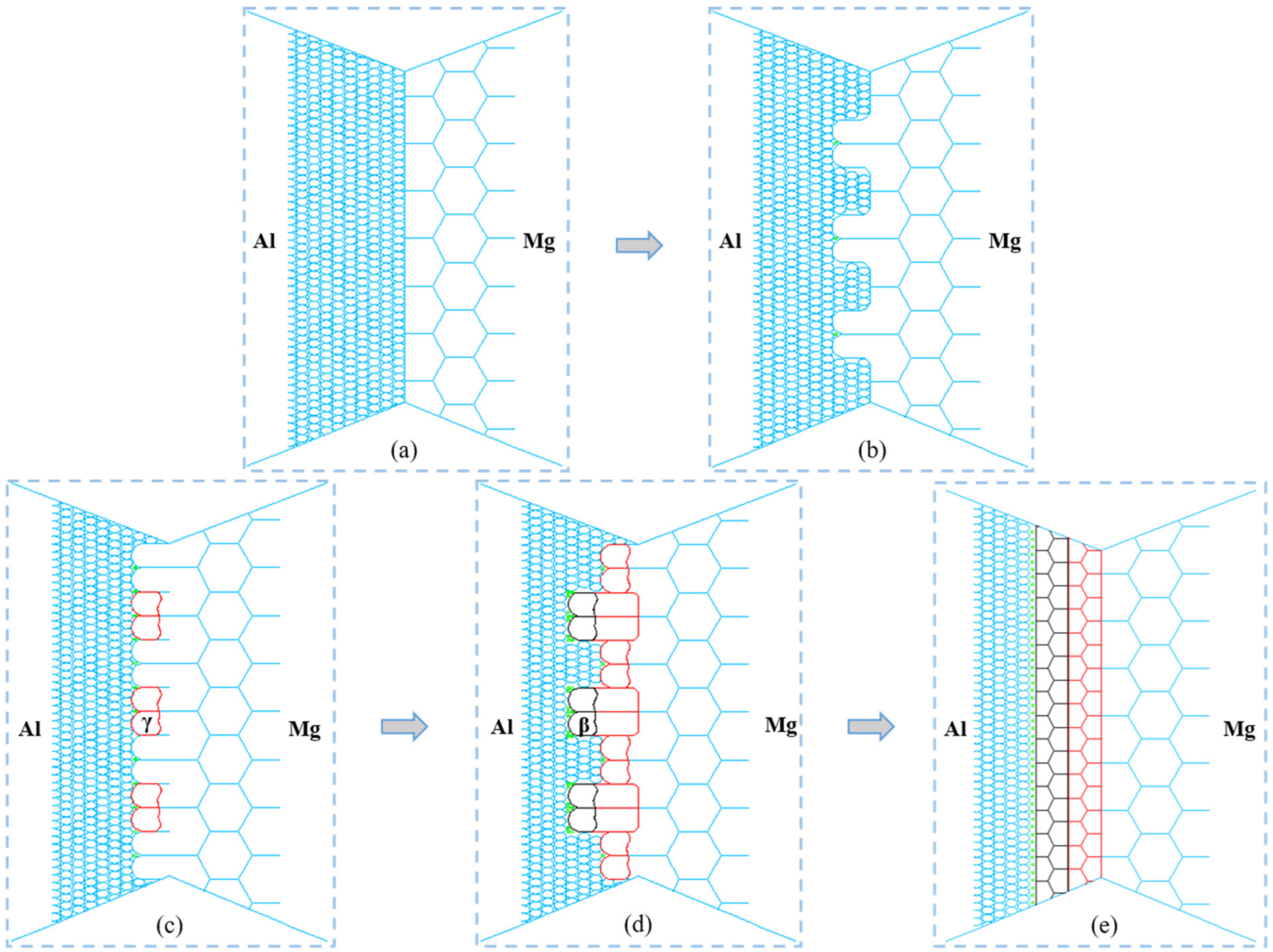
- In the dynamic recrystallization process during AA2024/AZ31B FSW, after the grain boundaries of Mg grains bulge and nucleate, the Al atoms quickly diffuse into Mg grains. The γ phase nucleates at the grain boundary and its growth rate into the original Mg grain is higher than that into the Al grain. The grain boundary bulge nucleation and phase transformation nucleation of Mg grain occur at the same time. The grain boundary of γ-phase bulges and nucleates. Then, the β-phase precipitates at the grain boundary of the γ-phase and preferentially grow into the original γ-phase grain. The continuous grain growth to the Al side makes the strengthening phase Cu bias to the side of the β phase. The recrystallization grain growth process of γ phase and β phase makes some changes in grain boundary position and angle and finally tends to be stable.
Author Contributions
Funding
Institutional Review Board Statement
Informed Consent Statement
Data Availability Statement
Conflicts of Interest
References
- Wu, C.S.; Lv, X.Q.; Su, H.; Shi, L. Research progress in dissimilar friction stir welding of Aluminium/Magnesium alloys. J. Mech. Eng. 2022, 56, 1–16. [Google Scholar]
- Shah, L.H.; Othman, N.H.; Gerlich, A. Review of research progress on aluminium–magnesium dissimilar friction stir welding. Sci. Technol. Weld. Join. 2018, 23, 256–270. [Google Scholar] [CrossRef]
- Wang, J.G.; Wang, Z.T. Progress in deformation aluminium alloys for aeronautic & astronautics industry. Light Alloy. Fabr. Technol. 2013, 41, 1–6. [Google Scholar]
- Zhong, H.; Liu, P.Y.; Zhou, T.H. Application and prospects of Magnesium and its alloys in aerospace. Aviat. Maint. Eng. 2002, 47, 41–42. [Google Scholar]
- Ma, Z.Y.; Shang, Q.; Ni, D.R.; Xiao, B.L. Friction stir welding of Magnisum alloys: A Review. Acta Metall. Sin. 2018, 54, 1597–1617. [Google Scholar]
- Sachin, K.; Wu, C.S. Review: Mg and Its Alloy—Scope, future perspectives and recent advancements in welding and processing. J. Harbin Inst. Technol. 2017, 24, 1–37. [Google Scholar]
- Liang, Z.; Chen, K.; Wang, X.; Yao, J.; Yang, Q.; Zhang, L.; Shan, A. Effect of Tool Offset and Tool Rotational Speed on Enhancing Mechanical Property of Al/Mg Dissimilar FSW Joints. Met. Mater. Trans. A 2013, 44, 3721–3731. [Google Scholar] [CrossRef]
- Fu, B.; Qin, G.; Li, F.; Meng, X.; Zhang, J.; Wu, C. Friction stir welding process of dissimilar metals of 6061-T6 aluminum alloy to AZ31B magnesium alloy. J. Mater. Process. Technol. 2014, 218, 38–47. [Google Scholar] [CrossRef]
- Yamamoto, N.; Liao, J.; Watanabe, S.; Nakata, K. Effect of Intermetallic Compound Layer on Tensile Strength of Dissimilar Friction-Stir Weld of a High Strength Mg Alloy and Al Alloy. Mater. Trans. 2009, 50, 2833–2838. [Google Scholar] [CrossRef] [Green Version]
- Rao, H.M.; Ghaffari, B.; Yuan, W.; Jordon, J.; Badarinarayan, H. Effect of process parameters on microstructure and mechanical behaviors of friction stir linear welded aluminum to magnesium. Mater. Sci. Eng. A 2016, 651, 27–36. [Google Scholar] [CrossRef] [Green Version]
- Verma, J.; Taiwade, R.V.; Sapate, S.G.; Patil, A.P.; Dhoble, A.S. Evaluation of Microstructure, Mechanical Properties and Corrosion Resistance of Friction Stir-Welded Aluminum and Magnesium Dissimilar Alloys. J. Mater. Eng. Perform. 2017, 26, 4738–4747. [Google Scholar] [CrossRef]
- Firouzdor, V.; Kou, S. Formation of Liquid and Intermetallics in Al-to-Mg Friction Stir Welding. Met. Mater. Trans. A 2010, 41, 3238–3251. [Google Scholar] [CrossRef]
- Liu, F.; Dong, P.; Zhang, J.; Lu, W.; Taub, A.; Sun, K. Alloy amorphization through nanoscale shear localization at Al-Fe interface. Mater. Today Phys. 2020, 15, 100252. [Google Scholar] [CrossRef]
- Zhao, Y.; Lu, Z.; Yan, K.; Huang, L. Microstructural characterizations and mechanical properties in underwater friction stir welding of aluminum and magnesium dissimilar alloys. Mater. Des. 2015, 65, 675–681. [Google Scholar] [CrossRef]
- Sato, Y.S.; Park, S.H.C.; Michiuchi, M.; Kokawa, H. Constitutional liquation during dissimilar friction stir welding of Al and Mg alloys. Scr. Mater. 2004, 50, 1233–1236. [Google Scholar] [CrossRef]
- Mofid, M.A.; Abdollah-Zadeh, A.; Ghaini, F.M. The effect of water cooling during dissimilar friction stir welding of Al alloy to Mg alloy. Mater. Des. 2012, 36, 161–167. [Google Scholar] [CrossRef]
- Chang, W.-S.; Rajesh, S.; Chun, C.-K.; Kim, H.-J. Microstructure and Mechanical Properties of Hybrid Laser-Friction Stir Welding between AA6061-T6 Al Alloy and AZ31 Mg Alloy. J. Mater. Sci. Technol. 2011, 27, 199–204. [Google Scholar] [CrossRef]
- Ji, S.; Huang, R.; Meng, X.; Zhang, L.; Huang, Y. Enhancing Friction Stir Weldability of 6061-T6 Al and AZ31B Mg Alloys Assisted by External Non-rotational Shoulder. J. Mater. Eng. Perform. 2017, 26, 2359–2367. [Google Scholar] [CrossRef]
- Kumar, S.; Wu, C. Suppression of intermetallic reaction layer by ultrasonic assistance during friction stir welding of Al and Mg based alloys. J. Alloy. Compd. 2020, 827, 154343. [Google Scholar] [CrossRef]
- Kwon, Y.J.; Shigematsu, I.; Saito, N. Dissimilar friction stir welding between magnesium and aluminum alloys. Mater. Lett. 2008, 62, 3827–3829. [Google Scholar] [CrossRef]
- Kang, J.; Fu, R.D.; Luan, G.H.; He, M. Effect of the offseting on microstructures and mechanical properties of FSW joints of 7075 Al alloys-AZ31B Mg alloys. Rare Met. Technol. 2011, 40, 294–299. [Google Scholar]
- Khodir, S.A.; Shibayanagi, T. Dissimilar Friction Stir Welded Joints between 2024-T3 Aluminum Alloy and AZ31 Magnesium Alloy. Mater. Trans. 2007, 48, 2501–2505. [Google Scholar] [CrossRef] [Green Version]
- Song, B. Study on Material Flow and Joint Property of the Dissimialr Friction Stir Joining for Mg and Al Alloys; Najing University of Aeronautics and Astronautics: Nanjing, China, 2017. [Google Scholar]
- Lv, X.; Wu, C.; Yang, C.; Padhy, G. Weld microstructure and mechanical properties in ultrasonic enhanced friction stir welding of Al alloy to Mg alloy. J. Mater. Process. Technol. 2018, 254, 145–157. [Google Scholar] [CrossRef]
- Zhao, J.; Wu, C.S.; Su, H. Ultrasonic effect on thickness variations of intermetallic compound layers in friction stir welding of aluminium/magnesium alloys. J. Manuf. Process. 2020, 62, 388–402. [Google Scholar] [CrossRef]
- Lv, X.Q.; Wu, C.S.; Sun, Z. Effects of ultrasonic vibration on material flow and thermal cycles in friction stir welding of dissimilar Al/Mg alloys. Metall. Mater. Trans. A 2022, 54, 1572–1584. [Google Scholar] [CrossRef]
- Zhao, J.; Wu, C.; Su, H. Ultrasonic vibration-induced thinning of intermetallic compound layers in friction stir welding of dissimilar Al/Mg alloys. Sci. Technol. Weld. Join. 2022, 27, 621–628. [Google Scholar] [CrossRef]
- Tan, M.J.; Wu, C.S.; Su, H. Ultrasonic effects on microstructures and mechanical properties of friction stir weld joints of dissimilar AA2024 /AZ31B alloys. Weld. World 2022. Online. [Google Scholar] [CrossRef]
- Yu, P.; Wu, C.; Shi, L. Analysis and characterization of dynamic recrystallization and grain structure evolution in friction stir welding of aluminum plates. Acta Mater. 2021, 207, 116692. [Google Scholar] [CrossRef]
- Huang, K.; Logé, R.E. A review of dynamR.E. ic recrystallization phenomena in metallic materials. Mater. Des. 2016, 111, 548–574. [Google Scholar] [CrossRef]


| Alloy | Nominal Chemical Composition (wt.%) | Mechanical Properties | |||||||||
|---|---|---|---|---|---|---|---|---|---|---|---|
| Si | Fe | Cu | Mn | Mg | Cr | Ti | Zn | Al | UTS(MPa) | EL (%) | |
| 2024-T4 | 0.252 | 0.158 | 4.44 | 0.651 | 1.37 | 0.13 | - | 0.094 | Bal. | 462 | 15 |
| AZ31B | 0.034 | 0.005 | 0.004 | 0.322 | Bal. | - | - | 0.936 | 3.91 | 251 | 11 |
Disclaimer/Publisher’s Note: The statements, opinions and data contained in all publications are solely those of the individual author(s) and contributor(s) and not of MDPI and/or the editor(s). MDPI and/or the editor(s) disclaim responsibility for any injury to people or property resulting from any ideas, methods, instructions or products referred to in the content. |
© 2022 by the authors. Licensee MDPI, Basel, Switzerland. This article is an open access article distributed under the terms and conditions of the Creative Commons Attribution (CC BY) license (https://creativecommons.org/licenses/by/4.0/).
Share and Cite
Tan, M.; Wu, C.; Shi, L. Formation Mechanism of Thicker Intermetallic Compounds in Friction Stir Weld Joints of Dissimilar AA2024/AZ31B Alloys. Materials 2023, 16, 51. https://doi.org/10.3390/ma16010051
Tan M, Wu C, Shi L. Formation Mechanism of Thicker Intermetallic Compounds in Friction Stir Weld Joints of Dissimilar AA2024/AZ31B Alloys. Materials. 2023; 16(1):51. https://doi.org/10.3390/ma16010051
Chicago/Turabian StyleTan, Maoju, ChuanSong Wu, and Lei Shi. 2023. "Formation Mechanism of Thicker Intermetallic Compounds in Friction Stir Weld Joints of Dissimilar AA2024/AZ31B Alloys" Materials 16, no. 1: 51. https://doi.org/10.3390/ma16010051