
Improving the Wear-Resistance of BT22 Titanium Alloy by Forming Nano-Cellular Topography via Laser-Thermochemical Processing
 , , , and
Abstract
:1. Introduction
2. Materials and Methods
3. Results and Discussion
4. Conclusions
Author Contributions
Funding
Data Availability Statement
Conflicts of Interest
References
- Wu, Z.; Kou, H.; Chen, N.; Xi, Z.; Fan, J.; Tang, B.; Li, J. Recent developments in cold dwell fatigue of titanium alloys for aero-engine applications: A review. J. Mater. Res. Technol. 2022, 20, 469–484. [Google Scholar] [CrossRef]
- Tardelli, J.D.C.; Bolfarini, C.; Cândido dos Reis, A. Comparative analysis of corrosion resistance between beta titanium and Ti-6Al-4V alloys: A systematic review. J. Trace Elem. Med. Biol. 2020, 62, 126618. [Google Scholar] [CrossRef]
- Pesode, P.; Barve, S.; Wankhede, S.V.; Jadhav, D.R.; Pawar, S.K. Titanium alloy selection for biomedical application using weighted sum model methodology. Mater. Today Proc. 2023, 72, 724–728. [Google Scholar] [CrossRef]
- Cai, Z.; Chen, J.; Zhang, Z.; Yang, K.; Li, X.; Xie, G. Microstructure regulation of titanium-oxygen alloy with high strength and excellent ductility for biomedical applications. Intermetallics 2022, 148, 107648. [Google Scholar] [CrossRef]
- Tkachuk, O.; Pohrelyuk, I.; Proskurnyak, R. Surface modification of titanium implants. KEM 2019, 813, 215–220. [Google Scholar] [CrossRef]
- Krasaesin, A.; Udonsom, S.; Baipaywad, P.; Sriwattanapong, K.; Nasongkla, N.; Porntaveetus, T.; Osathanon, T.; Watanabe, S.; Jongwannasiri, C.; Manaspon, C. Effect of plasma-nitrided titanium on mechanical properties and initial cell adhesion. Mater. Today Proc. 2023, in press. [Google Scholar] [CrossRef]
- Sandomierski, M.; Buchwald, T.; Patalas, A.; Voelkel, A. Improving the abrasion resistance of Ti6Al4V alloy by modifying its surface with a diazonium salt and attaching of polyurethane. Sci. Rep. 2020, 10, 19289. [Google Scholar] [CrossRef]
- Li, C.; Li, H.; van der Zwaag, S. Unravelling the abrasion resistance of two novel meta-stable titanium alloys on the basis of multi-pass-dual-indenter tests. Wear 2019, 440–441, 203094. [Google Scholar] [CrossRef]
- Łępicka, M.; Grądzka-Dahlke, M.; Pienia, D.; Pasierbiewicz, K.; Kryńska, K.; Niewczas, A. Tribological performance of titanium nitride coatings: A comparative study on TiN-coated stainless steel and titanium alloy. Wear 2019, 442–423, 68–80. [Google Scholar] [CrossRef]
- Fedirko, V.M.; Pohrelyuk, I.M.; Yas’kiv, O.I. Formation of functional coatings based on interstitial compounds on titanium under the conditions of thermodiffusion saturation. Mater. Sci. 2006, 42, 299–308. [Google Scholar] [CrossRef]
- Pang, X.; Yao, C.; Xiong, Z.; Gong, Q.; Sun, J.; Misra, R.D.K.; Li, Z. Comparative study of coatings with different molybdenum equivalent on titanium alloy forged plate for laser cladding: Microstructure and mechanical properties. Surf. Coat. Technol. 2022, 446, 128760. [Google Scholar] [CrossRef]
- Bai, H.; Zhong, L.; Kang, L.; Liu, J.; Zhuang, W.; Lv, Z.; Xu, Y. A review on wear-resistant coating with high hardness and high toughness on the surface of titanium alloy. J. Alloys Compd. 2021, 882, 160645. [Google Scholar] [CrossRef]
- Qin, D.; Lu, Y.; Guo, D.; Zheng, L.; Liu, Q.; Zhou, L. Tensile deformation and fracture of Ti-5Al-5V-5Mo-3Cr-1.5Zr-0.5Fe alloy at room temperature. Mater. Sci. Eng. A 2013, 587, 100–109. [Google Scholar] [CrossRef]
- Parida, A.K.; Maity, K. Analysis of some critical aspects in hot machining of Ti-5553 superalloy: Experimental and FE analysis. Def. Technol. 2019, 15, 344–352. [Google Scholar] [CrossRef]
- Ivasishin, O.M.; Markovsky, P.E.; Semiatin, S.L.; Ward, C.H. Aging response of coarse- and fine-grained β titanium alloys. Mater. Sci. Eng. A. 2005, 405, 296–305. [Google Scholar] [CrossRef]
- Anoshkin, N.F. Titanium Alloys. In Metallography of Titanium Alloys; Metallurgy: Moscow, Russia, 1980; 464p. [Google Scholar]
- Pohrelyuk, I.M.; Lavrys, S.M. Thermal stability of the deformed surface layer of VT22 titanium alloy in a nitrogen-containing medium. Mater. Sci. 2021, 57, 43–47. [Google Scholar] [CrossRef]
- Fedirko, V.M.; Pohrelyuk, I.M.; Luk’yanenko, O.H.; Lavrys’, S.M.; Kindrachuk, M.V.; Dukhota, O.I.; Tisov, O.V.; Zahrebel’nyi, V.V. Thermodiffusion saturation of the surface of VT22 titanium alloy from a controlled oxygen-nitrogen-containing atmosphere in the stage of aging. Mater. Sci. 2018, 53, 691–701. [Google Scholar] [CrossRef]
- Liu, J.; Wang, X.; Hu, Y.; Luo, L.; Jiang, C.; Liu, F.; Jin, W.; Zhu, K.; Long, Z.; Liu, K. Effect of hydrogen on microstructure and mechanical properties of plasma-nitrided pure titanium by cathodic cage plasma nitriding. Surf. Coat. Technol. 2023, 456, 129231. [Google Scholar] [CrossRef]
- Tarnowski, M.; Borowski, T.; Skrzypek, S.; Kulikowski, K.; Wierzchoń, T. Shaping the structure and properties of titanium and Ti6Al7Nb titanium alloy in low-temperature plasma nitriding processes. J. Alloys Comp. 2021, 864, 158896. [Google Scholar] [CrossRef]
- Wen, K.; Zhang, C.; Gao, Y. Influence of gas pressure on the low-temperature plasma nitriding of surface-nanocrystallined TC4 titanium alloy. Surf. Coat. Technol. 2022, 436, 128327. [Google Scholar] [CrossRef]
- Zong, X.; Wang, H.; Li, J.; Cheng, X.; Li, Z.; Tang, H. Microstructure characterization and evolution mechanism of titanium during laser surface nitriding. Mater. Charact. 2022, 190, 112029. [Google Scholar] [CrossRef]
- Abboud, J.H. Effect of processing parameters on titanium nitrided surface layers produced by laser gas nitriding. Surf. Coat. Technol. 2013, 214, 19–29. [Google Scholar] [CrossRef]
- Escalona, M.; Bhuyan, H.; Ibacache, S.; Retamal, M.J.; Saikia, P.; Borgohain, C.; Valenzuela, J.; Veloso, F.; Favre, M.; Wyndham, E. Study of titanium nitride film growth by plasma enhanced pulsed laser deposition at different experimental conditions. Surf. Coat. Technol. 2021, 405, 126492. [Google Scholar] [CrossRef]
- Katahira, K.; Tanida, Y.; Takesue, S.; Komotori, J. Rapid surface nitriding of titanium alloy by a nanosecond fiber laser under atmospheric conditions. CIRP Ann. 2018, 76, 563–566. [Google Scholar] [CrossRef]
- Kindrachuk, M.; Shevchenko, A.; Kryzhanovskyi, A. Improvement of the quality of TiC-Co system plasma coating by laser treatment. Aviation 2016, 20, 155–159. [Google Scholar] [CrossRef]
- Xin, Z.; Ren, N.; Ren, Y.; Yue, X.; Han, Q.; Zhou, W.; Tao, Y.; Ye, Y. In-situ nitriding on the textured titanium alloy using femtosecond laser. J. Mat. Res. Technol. 2022, 9, 466–471. [Google Scholar] [CrossRef]
- Senthilselvan, J.; Monisha, K.; Gunaseelan, M.; Yamini, S.; Arun Kumar, S.; Kanimozhi, K.; Manonmani, J.; Shariff, S.M.; Padmanabham, G. High power diode laser nitriding of titanium in nitrogen gas filled simple acrylic box container: Microstructure, phase formation, hardness, dendrite and martensite solidification analyses. Mater. Charact. 2020, 160, 110118. [Google Scholar] [CrossRef]
- Zong, X.; Wang, H.; Tang, H.; Cheng, X.; Tian, X.; Ran, X. Microstructure evolution and mass transfer behavior during multi-pass laser surface nitriding process on titanium alloy. Surf. Coat. Technol. 2023, 2023, 129565. [Google Scholar] [CrossRef]
- Ajikumar, P.K.; Kamruddin, M.; Shankar, P.; Gouda, R.; Balamurugan, A.K.; Nithya, R.; Tyagi, A.K.; Jayaram, V.; Biswas, S.K.; Raj, B. Internal nitride formation during gas-phase thermal nitridation of titanium. Scripta Mater. 2009, 61, 403–406. [Google Scholar] [CrossRef]
- Xu, S.; Cao, Y.; Duan, B.; Liu, H.; Wang, J.; Si, C. Enhanced strength and sliding wear properties of gas nitrided Ti-6Al-4V alloy by ultrasonic shot peening pretreatment. Surf. Coat. Technol. 2023, 458, 29325. [Google Scholar] [CrossRef]
- Toboła, D.; Morgiel, J.; Maj, Ł.; Pomorska, M.; Wytrwal-Sarna, M. Effect of tribo-layer developed during turning of Ti–6Al–4V ELI alloy on its low-temperature gas nitriding. Appl. Surf. Sci. 2022, 602, 154327. [Google Scholar] [CrossRef]
- Tisov, O.; Łępicka, M.; Tsybrii, Y.; Yurchuk, A.; Kindrachuk, M.; Dukhota, O. Duplex aging and gas nitriding process as a method of surface modification of titanium alloys for aircraft applications. Metals 2022, 12, 100. [Google Scholar] [CrossRef]
- Yu, Z.; Zhang, J.; Hu, J. Study on surface properties of nanosecond laser textured plasma nitrided titanium alloy. Mater. Today Commun. 2022, 31, 103746. [Google Scholar] [CrossRef]
- Liu, Q.; Liu, Y.; Li, X.; Dong, G. Pulse laser-induced cell-like texture on surface of titanium alloy for tribological properties improvement. Wear 2021, 477, 203784. [Google Scholar] [CrossRef]
- Mohammadi, M.; Akbari, A.; Warchomicka, F.; Pichon, L. Depth profiling characterization of the nitride layers on gas nitrided commercially pure titanium. Mater. Charact. 2021, 181, 111453. [Google Scholar] [CrossRef]
- Łępicka, M.; Grądzka-Dahlke, M. The initial evaluation of performance of hard anti-wear coatings deposited on metallic substrates: Thickness, mechanical properties and adhesion measurements—A brief review. Rev. Adv. Mater. 2019, 58, 50–65. [Google Scholar] [CrossRef]
- Kang, L.M.; Yang, C.; Zhao, Y.J.; Li, X.X.; Qu, S.G.; Zhang, W.W.; Long, Y.; Xiao, Z.Y. Bimodal eutectic titanium alloys: Microstructure evolution, mechanical behavior and strengthening mechanism. Mater. Sci. Eng. A 2017, 700, 10–18. [Google Scholar] [CrossRef]
- Chen, N.; Kou, H.; Wu, Z.; Qiang, F.; Hua, K.; Fan, J.; Tang, B.; Li, J.; Molina-Aldareguia, J.M. Microstructural sensitivity and deformation micro-mechanisms of a bimodal metastable β titanium Ti–7Mo–3Nb–3Cr–3Al alloy. Mater. Sci. Eng. A. 2021, 824, 141821. [Google Scholar] [CrossRef]
- Lee, H.J.; Kim, J.H.; Park, C.H.; Hong, J.K.; Yeom, J.T.; Lee, T.; Lee, S.W. Twinning-induced Plasticity Mechanism of α″-martensitic Titanium Alloy. Acta Mater. 2023, 248, 118763. [Google Scholar] [CrossRef]
- Rastogi, A.; Neelakantan, S. Enhanced thermo-mechanical processing through stress-induced martensitic transformation and its effect on grain refinement in metastable β titanium alloys. Scripta Mater. 2023, 226, 115222. [Google Scholar] [CrossRef]
- Lee, S.W.; Lee, H.J.; Kim, J.H.; Park, C.H.; Hong, J.K.; Yeom, J.-T. Effect of prior β grain size on the martensitic transformation of titanium alloys. Mater. Charact. 2021, 182, 111525. [Google Scholar] [CrossRef]
- Borisyuk, Y.V.; Oreshnikova, N.M.; Berdnikova, M.A.; Tumarkin, A.; Khodachenko, G.V.; Pisarev, A.A. Plasma nitriding of titanium alloy Ti5Al4V2Mo. Phys. Procedia 2015, 71, 105–109. [Google Scholar] [CrossRef]
- Pohrelyuk, I.M.; Kindrachuk, M.V.; Lavrys’, S.M. Wear resistance of VT22 titanium alloy after nitriding combined with heat treatment. Mater. Sci. 2016, 52, 56–61. [Google Scholar] [CrossRef]
- Zherebtsov, S.V.; Murzinova, M.A.; Klimova, M.V.; Salishchev, G.A.; Popov, A.A.; Semiatin, S.L. Microstructure evolution during warm working of Ti–5Al–5Mo–5V–1Cr–1Fe at 600 and 800 °C. Mater. Sci. Eng. A 2013, 563, 168–176. [Google Scholar] [CrossRef]
- Wang, H.; Xin, S.W.; Zhao, Y.Q.; Zhou, W.; Zeng, W.-D. Forging-microstructure-tensile properties correlation in a new near β high-strength titanium alloy. Rare Met. 2020, 40, 2109–2117. [Google Scholar] [CrossRef]
- Shen, H.; Wang, L. Formation, tribological and corrosion properties of thicker Ti-N layer produced by plasma nitriding of titanium in a N2-NH3 mixture gas. Surf. Coat. Technol. 2020, 393, 125846. [Google Scholar] [CrossRef]
- Zhecheva, A.; Malinov, S.; Sha, W. Titanium alloys after surface gas nitriding. Surf. Coat. Technol. 2006, 201, 2467–2474. [Google Scholar] [CrossRef]
- Tyunkov, A.V.; Golosov, D.A.; Zolotukhin, D.B.; Nikonenko, A.V.; Oks, E.M.; Yushkov, Y.G.; Yakovlev, E.V. Nitriding of titanium in electron beam excited plasma in medium vacuum. Surf. Coat. Technol. 2020, 383, 125241. [Google Scholar] [CrossRef]
- Dong, H. Surface engineering of light alloys. In Aluminium, Magnesium and Titanium Alloys, 1st ed.; Woodhead Publishing: Cambridge, UK, 2010; p. 680. [Google Scholar]


| Alloy | Al | V | Mo | Cr | Fe | Zr | General Properties |
|---|---|---|---|---|---|---|---|
| BT22 | 5.2 | 4.8 | 4.8 | 1.2 | 1 | <0.3 | UTS 1100–1400 MPa, good machinability, and weldability, elongation 10%. α-β transition point ~830 °C. the α-β ratio in annealed condition: ~50/50 [14]. |
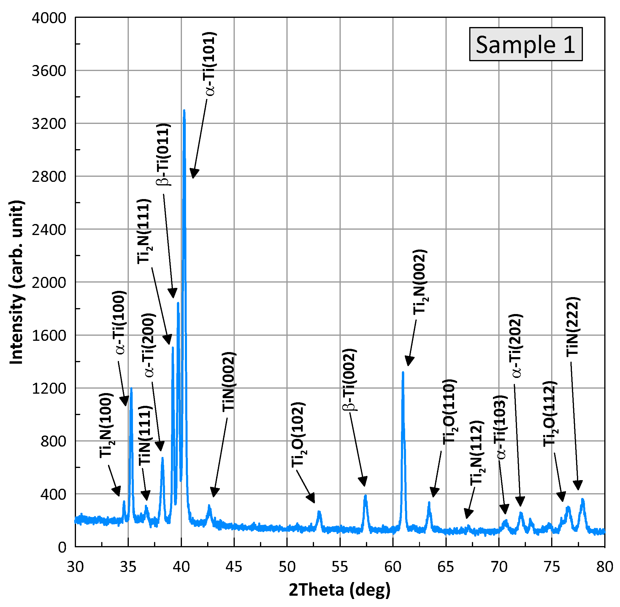
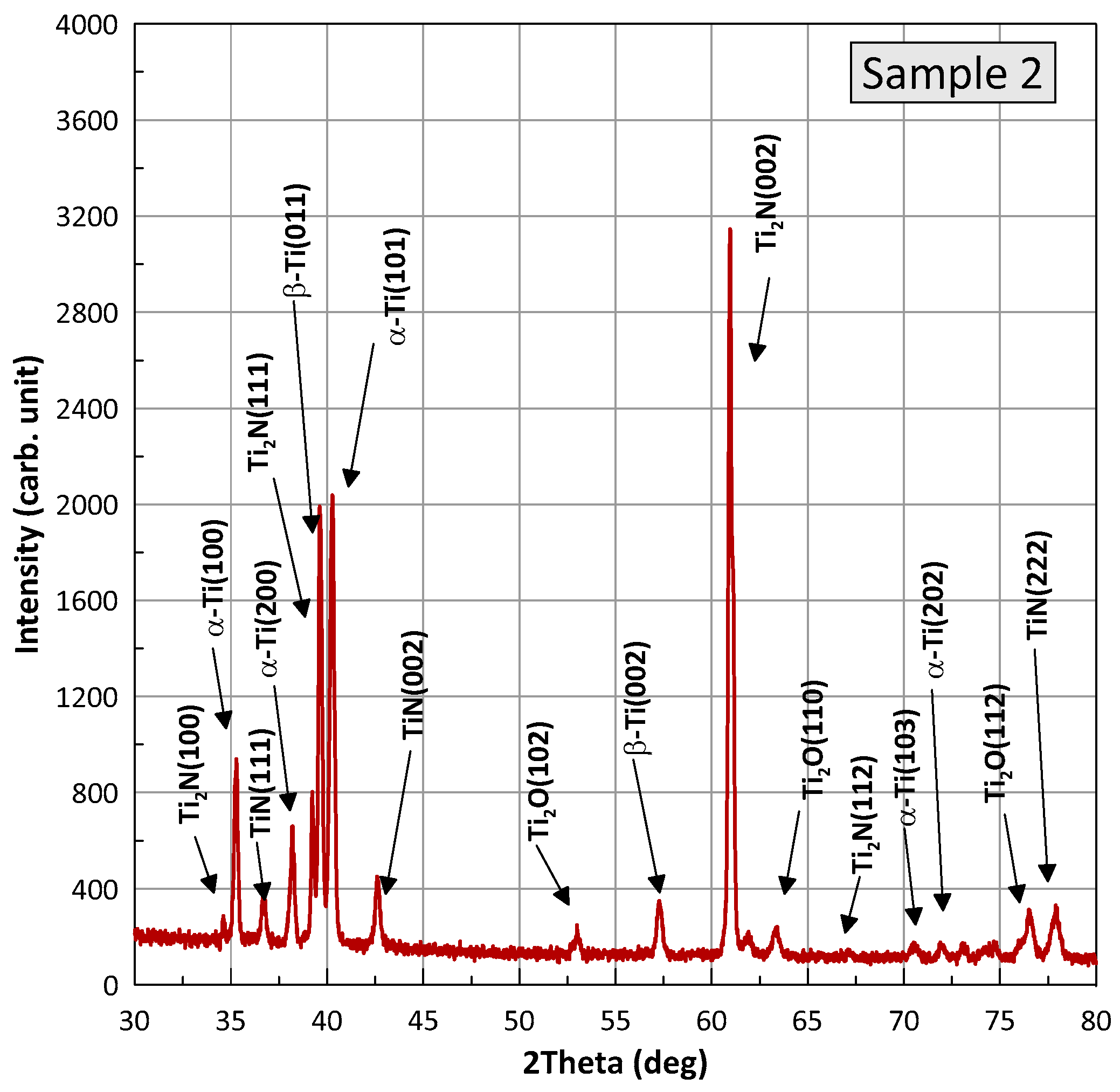
| Sample No. | α-Ti (%) | Ti2N (%) | TiN (%) | Ti2O (%) | β-Ti (%) |
|---|---|---|---|---|---|
| 1 | 53.9 | 17.7 | 6.9 | 17.6 | 3.9 |
| 2 | 43.0 | 16.0 | 9.0 | 24.0 | 8.0 |
| Sample | Location | Parameter | |
|---|---|---|---|
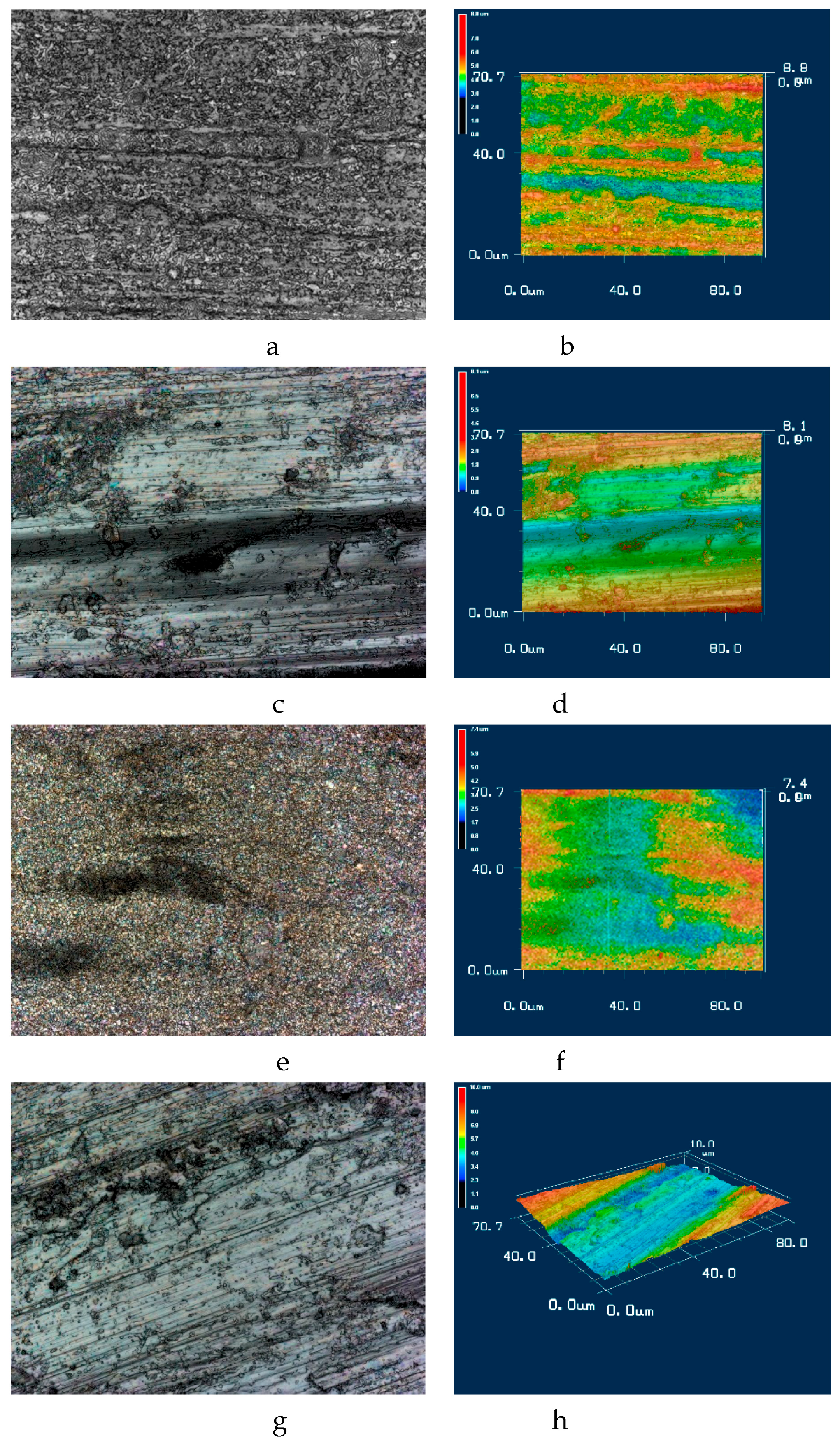
| Rz, μm | Ra, μm | ||
| 1 | Nitrided Surface | 2.81 | 0.36 |
| Wear track | 4.13 | 0.44 | |
| 2 | Nitrided Surface | 4.32 | 0.53 |
| Laser point | 2.23 | 0.19 | |
| Wear track | 4.56 | 1.08 | |
Disclaimer/Publisher’s Note: The statements, opinions and data contained in all publications are solely those of the individual author(s) and contributor(s) and not of MDPI and/or the editor(s). MDPI and/or the editor(s) disclaim responsibility for any injury to people or property resulting from any ideas, methods, instructions or products referred to in the content. |
© 2023 by the authors. Licensee MDPI, Basel, Switzerland. This article is an open access article distributed under the terms and conditions of the Creative Commons Attribution (CC BY) license (https://creativecommons.org/licenses/by/4.0/).
Share and Cite
Tisov, O.; Yurchuk, A.; Pashechko, M.; Pohreliuk, I.; Chocyk, D.; Kindrachuk, M. Improving the Wear-Resistance of BT22 Titanium Alloy by Forming Nano-Cellular Topography via Laser-Thermochemical Processing. Materials 2023, 16, 3900. https://doi.org/10.3390/ma16113900
Tisov O, Yurchuk A, Pashechko M, Pohreliuk I, Chocyk D, Kindrachuk M. Improving the Wear-Resistance of BT22 Titanium Alloy by Forming Nano-Cellular Topography via Laser-Thermochemical Processing. Materials. 2023; 16(11):3900. https://doi.org/10.3390/ma16113900
Chicago/Turabian StyleTisov, Oleksandr, Alina Yurchuk, Mykhaylo Pashechko, Iryna Pohreliuk, Dariusz Chocyk, and Myroslav Kindrachuk. 2023. "Improving the Wear-Resistance of BT22 Titanium Alloy by Forming Nano-Cellular Topography via Laser-Thermochemical Processing" Materials 16, no. 11: 3900. https://doi.org/10.3390/ma16113900