
Study on Corrosion Resistance of Stainless-Steel Welded Joints with SnSb8Cu4 and SnZn9

 ,
,
Abstract
:1. Introduction
2. Materials and Methods
2.1. Sample Preparation
2.2. Testing and Characterization
2.2.1. Melting Temperature
2.2.2. Shear Performance
2.2.3. Microstructure Analysis and Corrosion Morphology Observation
2.2.4. Analysis of Immersion Test
2.2.5. Analysis of Salt Spray Test
2.2.6. Electrochemical Analysis
3. Results and Discussion
3.1. Brazing Performance of Solders
3.2. Microstructural Studies of Compounds
3.3. Corrosion Weight Loss Analysis
3.4. Analysis of Salt Spray Tests
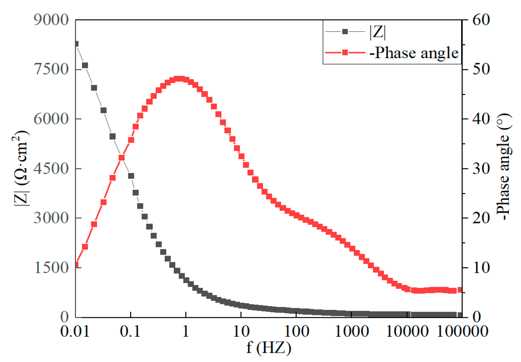
3.5. Electrochemical Analysis
4. Conclusions
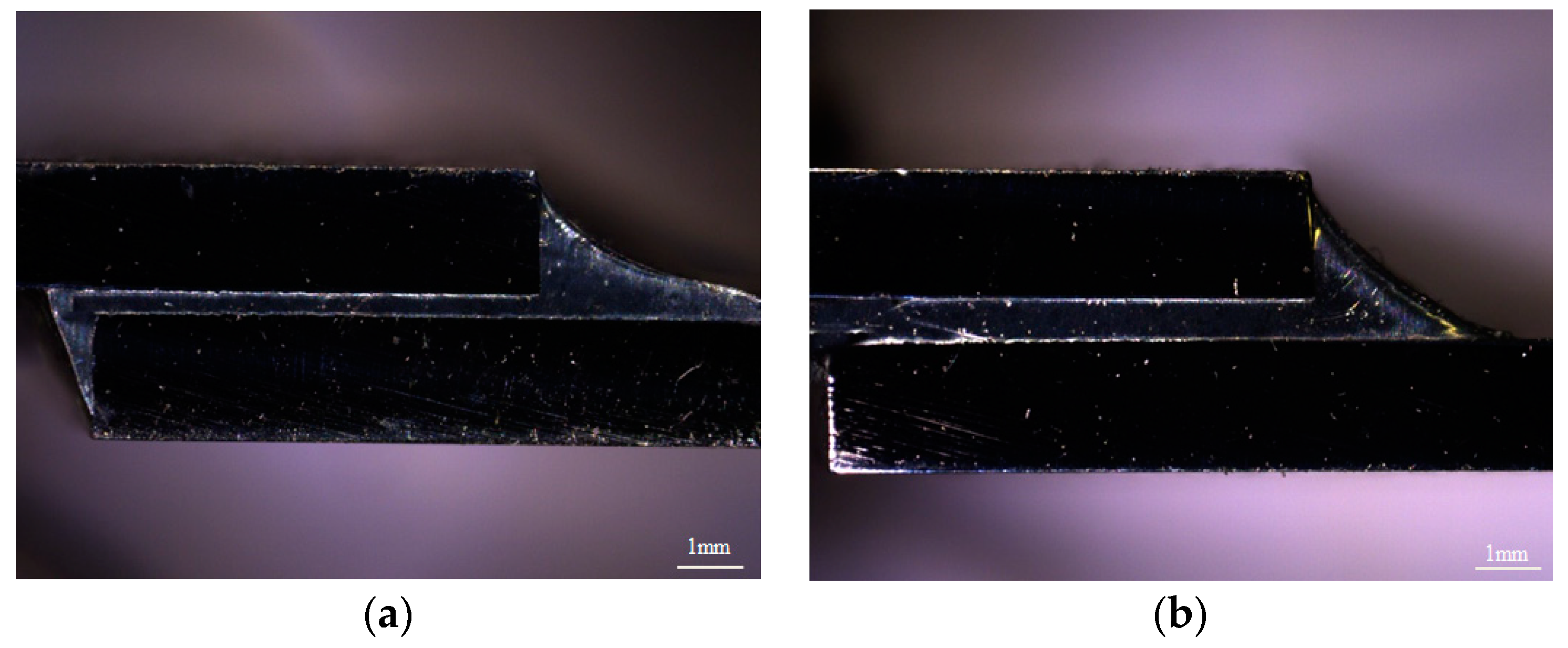
- The Sn-Zn9 and Sn-Sb8-Cu4 solders are capable of replacing the sealants used to seal the stainless-steel car body. After sealing, the surface of the brazing seam may be well formed, smooth, and continuous, with almost no deformation after welding; the surface does not change color.
- The Sn-Zn9 and Sn-Sb8-Cu4 solders have exhibited excellent wetting properties, spreading properties, and sealing strength in this experiment on stainless-steel sealing soldering.
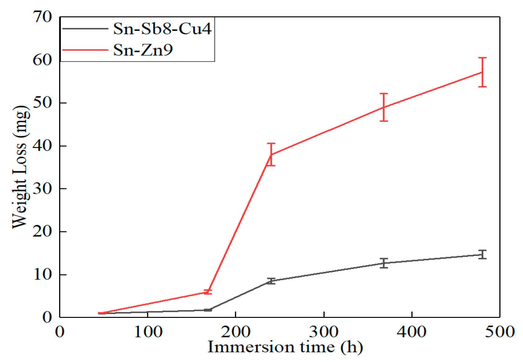
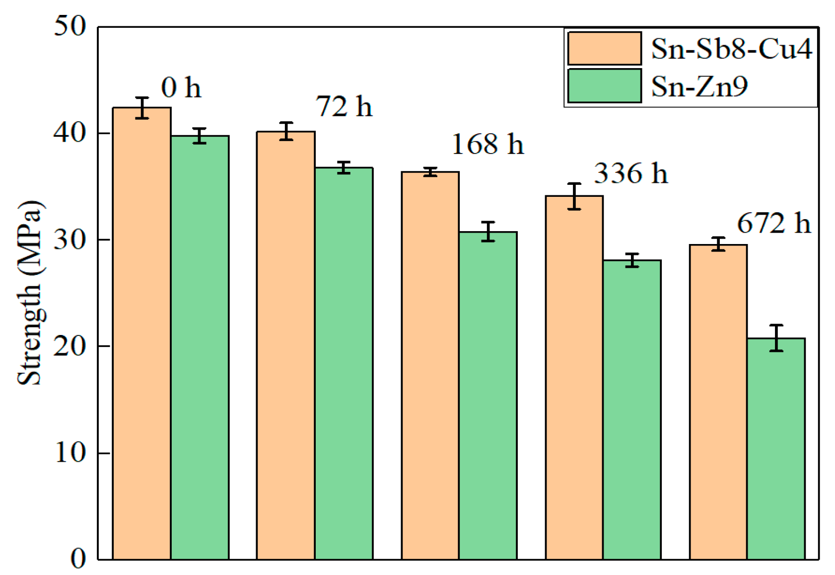
- In comparison with the Sn-Zn9 solder, the Sn-Sb8-Cu4 solder exhibits better corrosion resistance in immersion, salt spray, and electrochemical experiments.
Author Contributions
Funding
Institutional Review Board Statement
Informed Consent Statement
Data Availability Statement
Conflicts of Interest
References
- Cheng, G.; Cheng, P.; Chao, M.A. Application of Spot Welding in the Manufacture of Stainless Steel Rail Transit Vehicle. Urban Mass Transit 2019, 2, 4–6. [Google Scholar] [CrossRef]
- Guo, T.; Zhang, Q.; Sun, X.; Han, X.; Li, Y. Influence of Adhesive Sealant on Resistance Spot Welding of Stainless Steel Sheets with Different Thickness. China Mech. Eng. 2018, 29, 3009–3013. [Google Scholar] [CrossRef]
- Sun, X.; Zhang, Q.; Wang, S.; Han, X.; David, S.A. Effect of adhesive sealant on resistance spot welding of 301L stainless steel. J. Manuf. Process. 2020, 51, 62–72. [Google Scholar] [CrossRef]
- Huang, Y.H.; Li, X.; Michelon, M.; Bruna, C.L.; Frostad, J.M. Effects of aging on the shelf life and viscoelasticity of gellan gum microcapsules. Food Hydrocoll. 2021, 121, 982–987. [Google Scholar] [CrossRef]
- Zhang, Z.; Shan, J.; Wu, A.; Ren, J. Study on high speed laser-MIG hybrid welding for large gap joint of stainless steel sheet. Trans. China Weld. Inst. 2015, 10, 109–112. [Google Scholar]
- Moinuddin, S.Q.; Sharma, A. Arc behavior study using welding current module and its impact on residual stress and weld bead in anti-phase synchronized twin-wire gas metal arc welding. Indian Weld. J. 2019, 51, 73–79. [Google Scholar] [CrossRef]
- Qin, G.; Lei, Z.; Su, Y.; Fu, B.; Lin, S. Large spot laser assisted GMA brazing–fusion welding of aluminum alloy to galvanized steel. J. Mater. Process. Technol. 2014, 214, 2684–2692. [Google Scholar] [CrossRef]
- Zhang, Y.; Chen, Y.K.; Zhou, J.P.; Zhou, J.P.; Li, H.M. Laser welding-brazing of alumina to 304 stainless steel with an Ag-based filler material. Metall. Res. Technol. 2021, 118, 104. [Google Scholar] [CrossRef]
- Sun, H.; Yu, G.; Chen, S.; Huang, J.; Yang, J. Effect of Zn Al filler metals on the characteristics of the joint made by the high-frequency induction brazing of 304 stainless steel and 6A02 aluminum. J. Manuf. Process. 2021, 68, 961–972. [Google Scholar] [CrossRef]
- Pea, N.R.; Vazquez, L.; Arruti, E.; Alvarez, P.; Tabernero, I. Wire and arc additive manufacturing: A comparison between CMT and TopTIG processes applied to stainless steel. Weld. World 2018, 62, 1083–1096. [Google Scholar] [CrossRef]
- Liu, H.; Cheng, Z.; Huang, J.; Ye, Z.; Yang, J.; Chen, S.; Zhao, X. Feasibility study of different filler metals on MIG-TIG double-sided arc brazing of titanium alloy-stainless steel. J. Manuf. Process. 2019, 47, 183–191. [Google Scholar] [CrossRef]
- Salcianu, C.L.; Bordeau, I.; Srbu, N.A.; Bdru, R.; Hluscu, M.; Prvulescu, L.D.; Ostoia, D.; Oanc, O.V. Assessment of the Cavitation Resistance of Stainless Steel X5crni18-10, Subjected to Thermal Sensitization Based on Average Durability. Adv. Mater. Res. 2020, 1157, 52–57. [Google Scholar] [CrossRef]
- Van Niekerk, C.J.; Du Toit, M. Sensitization behaviour of 11-12% Cr AISI 409 stainless steel during low heat input welding. J. South. Afr. Inst. Min. Metall. 2011, 111, 243–255. [Google Scholar] [CrossRef]
- Chung, T.; Kim, J.; Bang, J.; Rhee, B.; Nam, D. Microstructures of brazing zone between titanium alloy and stainless steel using various filler metals. Trans. Nonferrous Met. Soc. China. 2012, S3, 639–644. [Google Scholar] [CrossRef]
- Shen, Z.; Arioka, K.; Lozano-Perez, S. A study on the diffusion-induced grain boundary migration ahead of stress corrosion cracking crack tips through advanced characterization. Corros. Sci. J. Environ. Degrad. Mater. Its Control. 2021, 183, 109328. [Google Scholar] [CrossRef]
- Dharmendra, C.; Rao, K.P.; Wilden, J.; Reich, S. Study on laser welding–brazing of zinc coated steel to aluminum alloy with a zinc based filler. Mater. Sci. Eng. A 2011, 528, 1497–1503. [Google Scholar] [CrossRef]
- Diaz, A.J.; Ma, D.; Zinn, A.; Quintero, P.O. Tin Nanoparticle-Based Solder Paste for Low Temperature Processing. J. Microelectron. Electron. Packag. 2013, 10, 129–137. [Google Scholar] [CrossRef]
- Yu, J.; Welford, R.; Hills, P. Industry responses to EU WEEE and ROHS directives: Perspectives from China. Corp. Soc. Responsib. Environ. Manag. 2012, 13, 286–299. [Google Scholar] [CrossRef]
- Mahajan, P.; Datt, R.; Tsoi, W.C.; Gupta, V.; Tomar, A.; Arya, S. Recent progress, fabrication challenges and stability issues of lead-free tin-based perovskite thin films in the field of photovoltaics. Coord. Chem. Rev. 2020, 429, 213633. [Google Scholar] [CrossRef]
- Zhou, X.; Long, W.; Pei, K. Study on solders and flux for stainless steel soldering. Welding 2014, 58, 26–29. [Google Scholar] [CrossRef]
- Wai, L.C.; Yamamoto, K.; Boon, S.; Tang, G.Y. Power Module on Copper Lead Frame with Novel Sintering Paste and SnSb solder. In Proceedings of the 2020 IEEE 22nd Electronics Packaging Technology Conference (EPTC), New York, NY, USA, 2 December 2020. [Google Scholar]
- Hirai, Y.; Oomori, K.; Morofushi, H.; Shohji, I. Microstructure and Tensile Properties of Sn-Ag-Cu-In-Sb Solder. Mater. Sci. Forum 2021, 1016, 553–560. [Google Scholar] [CrossRef]
- Zhang, P.; Xue, S.; Wang, J. New challenges of miniaturization of electronic devices: Electromigration and thermomigration in lead-free solder joints. Mater. Des. 2020, 192, 106–108. [Google Scholar] [CrossRef]
- Zhang, L.; Han, J.G.; Guo, Y.H.; Cheng, W.H. Microstructures and Properties of SnZn Lead-Free Solder Joints Bearing La for Electronic Packaging. IEEE Trans. Electron Devices 2012, 59, 3269–3272. [Google Scholar] [CrossRef]
- Liu, J.C.; Wang, Z.H.; Xie, J.Y.; Ma, J.S.; Suganuma, K. Effects of intermetallic-forming element additions on microstructure and corrosion behavior of SnZn solder alloys. Corros. Sci. 2016, 112, 150–159. [Google Scholar] [CrossRef]
- Abioye, T.E.; Zuhailawati, H.; Azlan MA, I.; Anasyida, A.S. Effects of SiC additions on the microstructure, compressive strength and wear resistance of Sn-Sb-Cu bearing alloy formed via powder metallurgy. J. Mater. Res. Technol. 2020, 9, 13196–13205. [Google Scholar] [CrossRef]
- Xu, H.; He, T.; Zhong, N.; Zhao, B.; Liu, Z. Transient thermomechanical analysis of micro cylindrical asperity sliding contact of SnSbCu alloy. Tribol. Int. 2022, 167, 107362. [Google Scholar] [CrossRef]
- Liu, Y.; Li, G.Q.; Wang, S.X.; Han, X.H.; Wang, B.; Ye, J.H.; Wang, J.T. Study on microstructure and properties of stainless steel thin plate lap laser sealing brazing. J. Weld. 2022. accected. [Google Scholar]
- GB/T 1771-2007; Determination of Neutral Salt Spray Resistance of Paints and Varnishes. National Standard: Singapore, 2007.
- Qi, Y.; Shen, C.; Xu, H. Corrosion resistance of friction stir welded joints of aluminum alloy 6005A. J. Dalian Jiaotong Univ. 2019, 40, 5. [Google Scholar]
- GB/T 17359-2012; Microbeam Analysis-Quantitative Analysis Using Energy Dispersive Spectrometry. National Standard: Singapore, 2012.


| C | P | Si | Mn | Ni | Cr | Fe |
|---|---|---|---|---|---|---|
| 0.07 | ≤0.045 | ≤0.030 | 2.00 | 8–11 | 18–20 | residual amount |
| Sb | Cu | Fe | As | Al | Sn |
|---|---|---|---|---|---|
| 7.72 | 3.81 | ≤0.005 | ≤0.004 | 0.013 | residual amount |
| Zn | Cu | Fe | As | Al | Sn |
|---|---|---|---|---|---|
| 8.82 | 0.01 | ≤0.005 | ≤0.004 | 0.013 | residual amount |
| Number | Temperature/°C | Time/min | Area/mm2 |
|---|---|---|---|
| 1 | 280 | 3.5 | 44.61 |
| 2 | 280 | 3.5 | 46.31 |
| 3 | 280 | 3.5 | 48.14 |
| Number | Temperature/°C | Time/min | Area/mm2 |
|---|---|---|---|
| 1 | 280 | 3.5 | 48.53 |
| 2 | 280 | 3.5 | 44.80 |
| 3 | 280 | 3.5 | 42.66 |
| Number | Temperature/°C | Time/min | Area/mm2 |
|---|---|---|---|
| 1 | 280 | 3.5 | 51.13 |
| 2 | 280 | 3.5 | 49.89 |
| 3 | 280 | 3.5 | 51.68 |
Disclaimer/Publisher’s Note: The statements, opinions and data contained in all publications are solely those of the individual author(s) and contributor(s) and not of MDPI and/or the editor(s). MDPI and/or the editor(s) disclaim responsibility for any injury to people or property resulting from any ideas, methods, instructions or products referred to in the content. |
© 2023 by the authors. Licensee MDPI, Basel, Switzerland. This article is an open access article distributed under the terms and conditions of the Creative Commons Attribution (CC BY) license (https://creativecommons.org/licenses/by/4.0/).
Share and Cite
Wang, J.; Wang, S.; Wang, B.; Han, X.; Liu, Y.; Ye, J.; Cheng, Z. Study on Corrosion Resistance of Stainless-Steel Welded Joints with SnSb8Cu4 and SnZn9. Materials 2023, 16, 3908. https://doi.org/10.3390/ma16113908
Wang J, Wang S, Wang B, Han X, Liu Y, Ye J, Cheng Z. Study on Corrosion Resistance of Stainless-Steel Welded Joints with SnSb8Cu4 and SnZn9. Materials. 2023; 16(11):3908. https://doi.org/10.3390/ma16113908
Chicago/Turabian StyleWang, Jintao, Shengxi Wang, Bo Wang, Xiaohui Han, Yong Liu, Jiehe Ye, and Zhan Cheng. 2023. "Study on Corrosion Resistance of Stainless-Steel Welded Joints with SnSb8Cu4 and SnZn9" Materials 16, no. 11: 3908. https://doi.org/10.3390/ma16113908
APA StyleWang, J., Wang, S., Wang, B., Han, X., Liu, Y., Ye, J., & Cheng, Z. (2023). Study on Corrosion Resistance of Stainless-Steel Welded Joints with SnSb8Cu4 and SnZn9. Materials, 16(11), 3908. https://doi.org/10.3390/ma16113908