2.1. Materials
The raw material for the experiments was ground granulated blast furnace slag (GGBFS), which was provided by ISD DUNAFERR Zrt. (Dunaújváros, Hungary). For the purpose of comparison with other aluminosilicate sources, test specimens were prepared using Metaver R type metakaolin (MK) (Newchem GmbH, Baden, Austria) and fly ash (FA) (MVM Mátra Energia Zrt., Visonta, Hungary). The chemical composition of the starting materials (
Table 1) was determined by X-ray fluorescence spectrometry (XRFS), the mineral composition (
Table 2) by X-ray diffraction (XRD), and the amount of each phase by Rietveld Analysis.
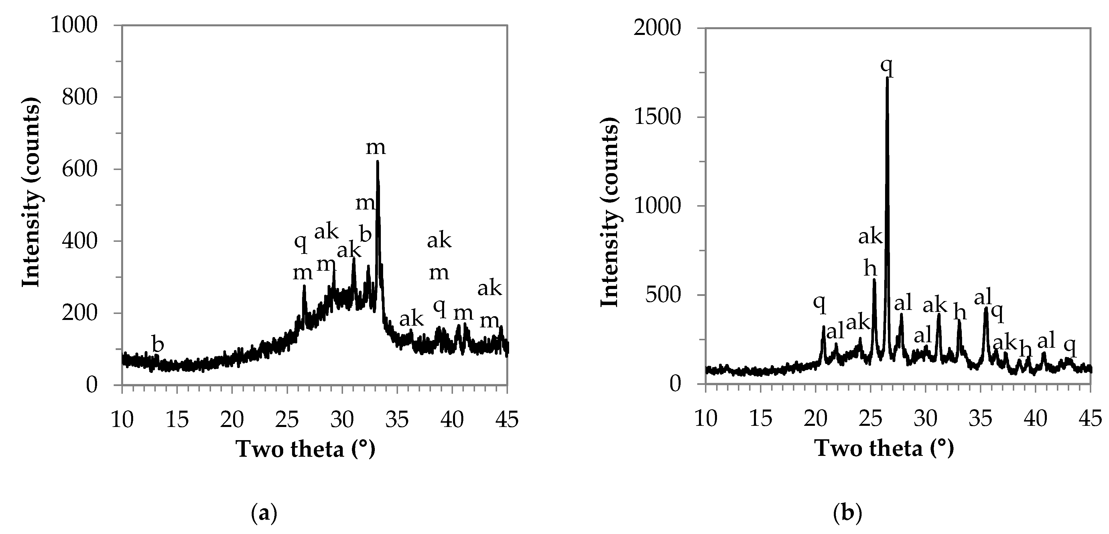
Based on the XRD analysis of the raw materials (see
Figure A1 in
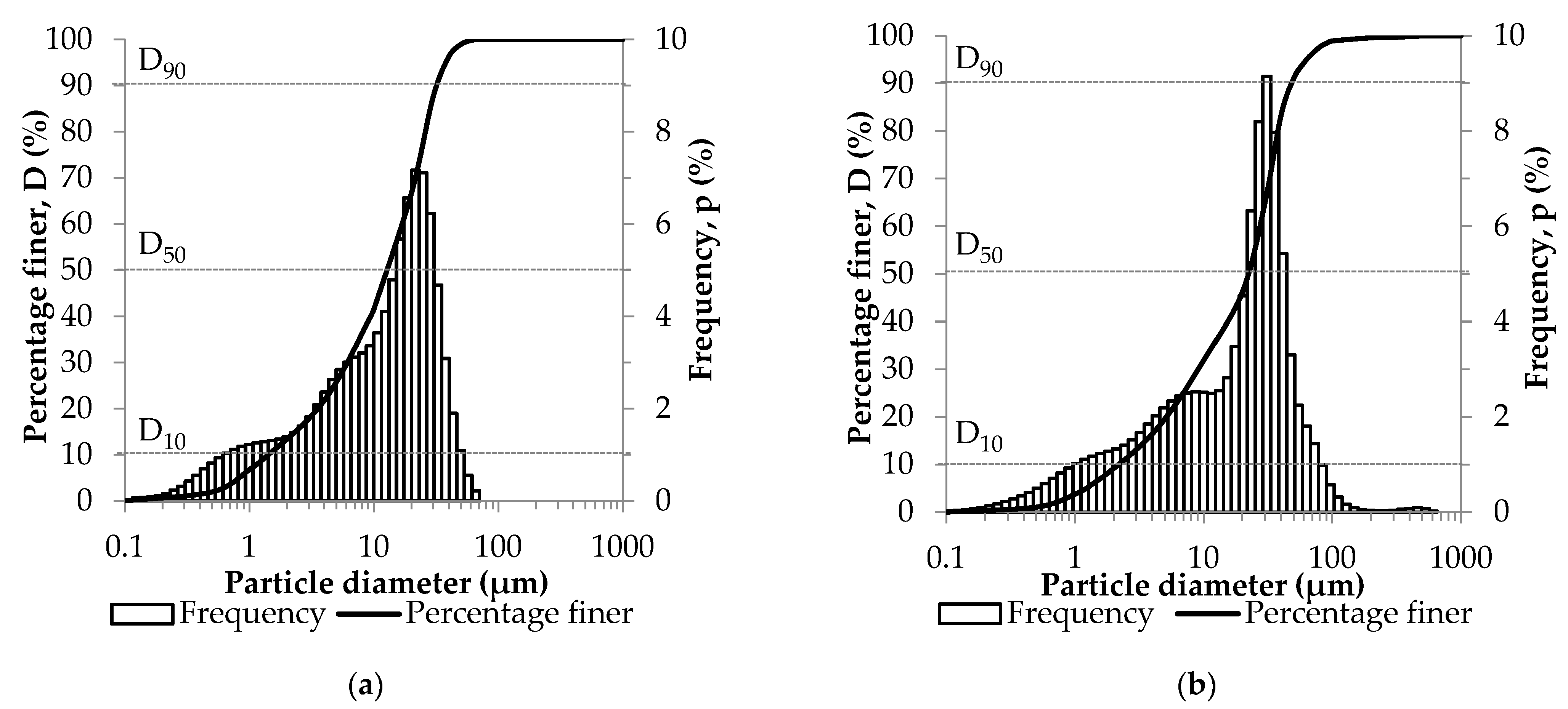
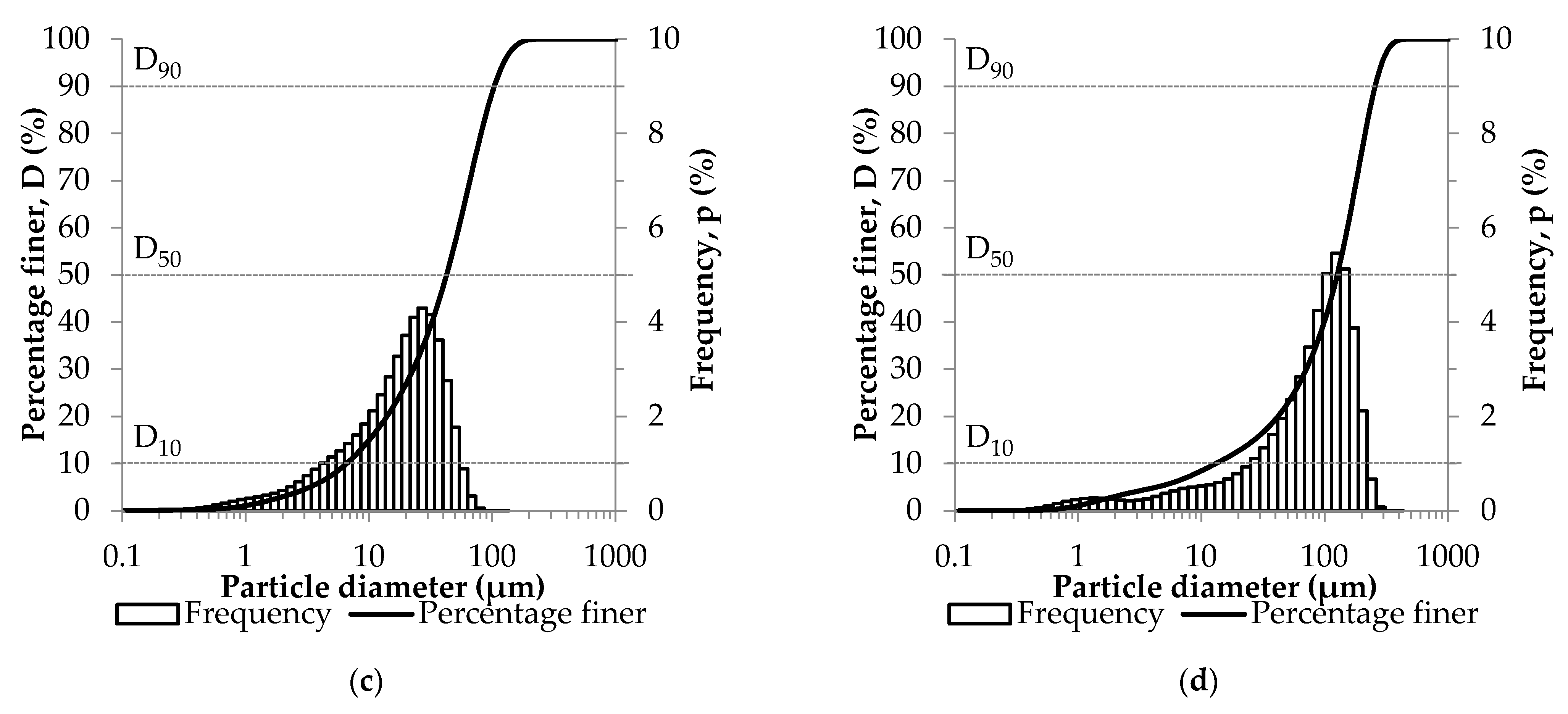
Appendix A), it can be said that all three materials contain a large amount of amorphous phase. In the case of GGBFS, the crystalline phases are merwinite, akermanite, bronwmillerite, and quartz, in the case of MK quartz, calcite, and hematite, and in the case of FA akermanite, quartz, hematite, and albite. The particle size distribution of aluminosilicate sources and their median (D50) were determined with the help of a laser granulometer, GGBFS: 25.8% < 5 μm, D50 = 13.84 μm; MK: 19.6% < 5 μm, D50 = 22.45 μm; FA: 7.9% < 5 μm, D50 = 42.62 μm (see
Figure A2 in
Appendix A).
For the preparation of AAC mortars, in the case of control samples, standard quartz sand (CEN Standard Sand according to DIN EN 196-1 [
46], Normensand GmbH, Beckum, Germany) was used as a filler, while in the case of alternative aggregate mixtures, waste concrete (WC) powder from construction and demolition activities (Beton Technológia Centrum Kft., Budapest, Hungary) was used; the chemical composition of the latter is shown in
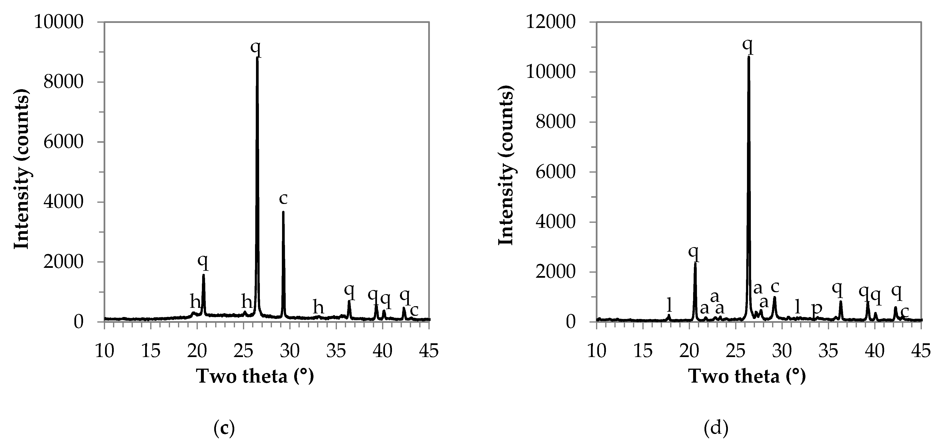
Table 3. Based on the X-ray recording (see
Figure A1 in
Appendix A), the WC contains a small amount of amorphous phase, the main crystalline phase is quartz, and in addition, calcite, anorthite, larnite, and portlandite are also present as minor components (
Table 4).
The maximum particle size of standard quartz sand is 2 mm, while that of waste concrete is 0.5 mm. The aggregates were divided into fractions with the help of sieve analysis, and the particle size distribution is shown in
Table 5. The exact particle size distribution of waste concrete and the median (D50) were determined with the help of a laser granulometer: 5.5% < 5 μm, and D50 = 125.66 μm (see
Figure A2 in
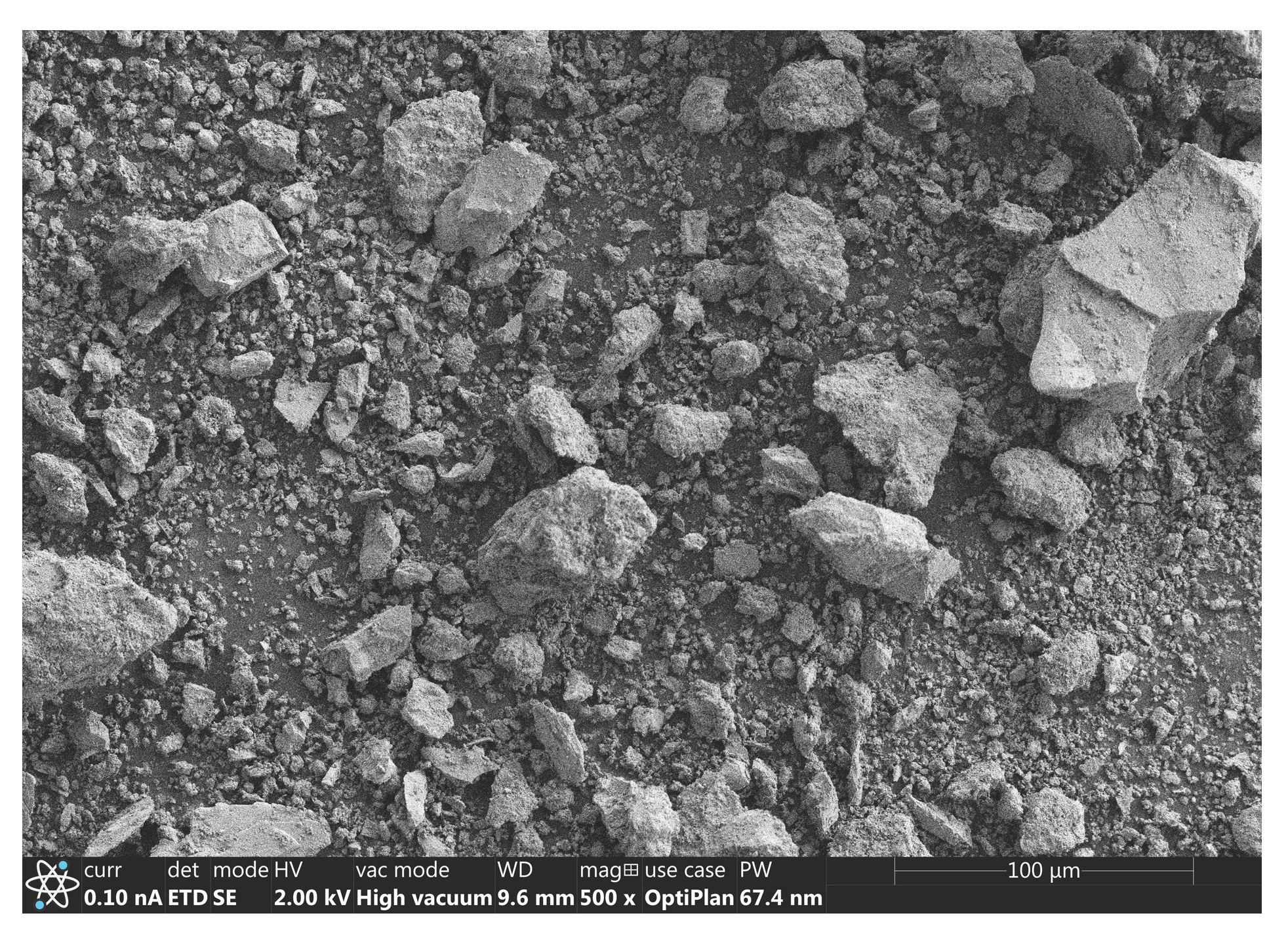
Appendix A). The morphology of WC is shown in
Figure A3 in
Appendix A.
The alkaline medium (activating solution) required for the preparation of AACs was provided by a mixture of analytical grade NaOH pellets (Reanal Laborvegyszer Kereskedelmi Kft., Budapest, Hungary) and a commercially available sodium silicate solution (ANDA Kft., Barcs, Hungary). The chemical composition of the latter was as follows: 6.8 wt% Na2O, 28.6 wt% SiO2, and 64.6 wt% H2O.
During the foaming process, sodium oleate (Sigma-Aldrich Chemie GmbH, Steinheim, Germany) was used as a stabilizing agent, and a solution of 30 wt% of H
2O
2 (Reanal Laborvegyszer Kereskedelmi Kft., Budapest, Hungary) diluted to 4.5 wt% as a foaming agent (based on research settings by Boros et al. [
35]).
2.2. Sample Preparation
In experimental work, “dense” and foamed AACs were prepared. In both cases, the activating solution was prepared in the same way: solid NaOH was dissolved directly in Na2SiO3 solution (and in distilled water). For the reason of reproducibility, all mixtures were prepared using an activating solution cooled to room temperature.
For the production of the AAC mortars (“dense”), the required amount of raw material (GGBFS, MK, or FA) was first measured, then the appropriately cooled activating solution was added. Identical conditions were ensured during the mixing, i.e., the slurry of raw material–alkaline solution was homogenized for 1 min at 900 rpm, then the aggregate (standard quartz sand or waste concrete) was added (with a 1:2 raw material: aggregate mass ratio). The resulting mortar was further mixed for 1 min at 900 rpm.
The steps for the preparation of AAC foams up to the addition of the foaming components were the same as for “dense” specimens (the slurry of the starting material–alkaline solution for 1 min at 900 rpm, +waste concrete for 1 min at 900 rpm). After homogenization of the waste concrete in the AAC slurry, sodium oleate was added. The resulting mixture was further stirred for 1 min at 1200 rpm, and finally, the H2O2 solution was added and homogenized for 1 min at 600 rpm.
The prepared fresh mixture was cast into ø30 mm × 30 mm cylindrical PVC molds for both “dense” and foamed AACs and was stored under ambient conditions (21–23 °C and RH = 50 ± 10%). Samples were demolded at 1 day of age, and the qualification tests were performed at 7 and 28 days of age. In this study, the 28-day average test results were reported.
In the first stage, GGBFS-based AAC mortar specimens were prepared using the following molar ratios: SiO
2/Al
2O
3 = 6.6, Na
2O/Al
2O
3 = 1.1, the mass ratio of Na
2SiO
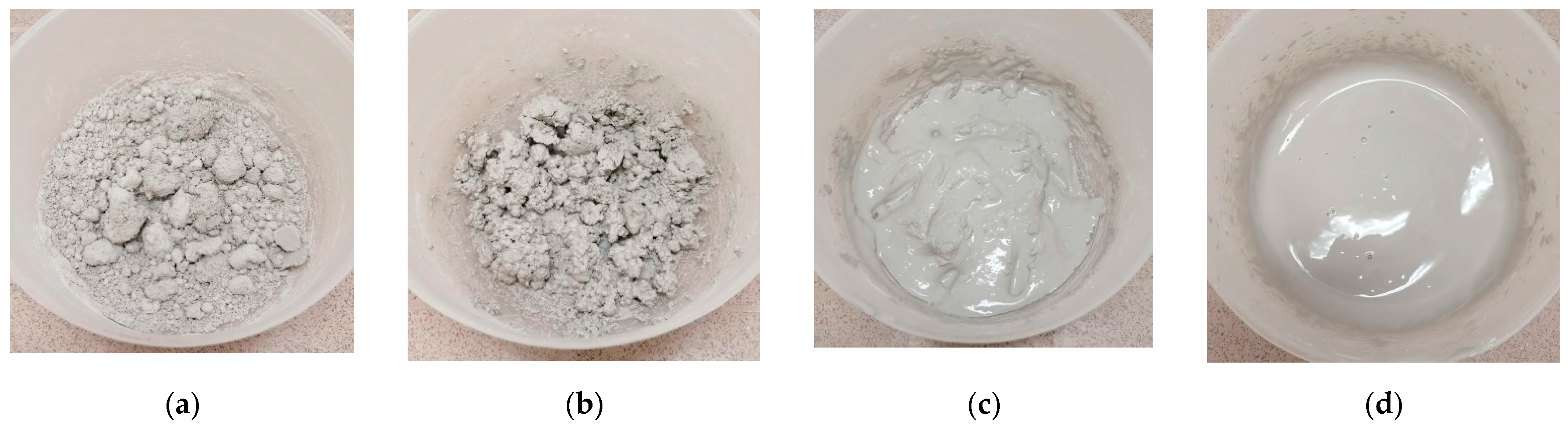
3 to NaOH in the activating solution was 6.6, and that of the activating solution and blast furnace slag powder was 0.6. First, control samples containing standard quartz sand were prepared, then the total amount of the aggregate was replaced with waste concrete. Different liquid/solid (L/S) ratios (0.21, 0.315, 0.368, and 0.42) were used to determine the appropriate mixing consistency (
Figure 1). The increase in liquid content of the mixtures was obtained by increasing the amount of activating solution, which modified the applied molar ratios as shown in
Table 6.
The experimental work was continued by dividing the aggregates into various fractions, and then using the standard quartz sand and the waste concrete with the same particle size to prepare test specimens. The L/S ratio was varied between 0.315 and 0.42, as in the previous experimental phase.
To determine the reactivity of the construction and demolition waste used, AAC specimens were prepared using only waste concrete (without the addition of slag) by varying the L/S ratio (0.315–0.42). The molar ratios used were as follows: SiO2/Al2O3 = 3.4, 3.8, and 4.1, respectively, Na2O/Al2O3 = 1.4, 1.6, and 1.9, respectively. The composition of the alkaline medium was the same as the alkaline solution used in the previous sections, and the mass ratio of the activating solution to the concrete powder was 0.28, 0.32, and 0.37, respectively.
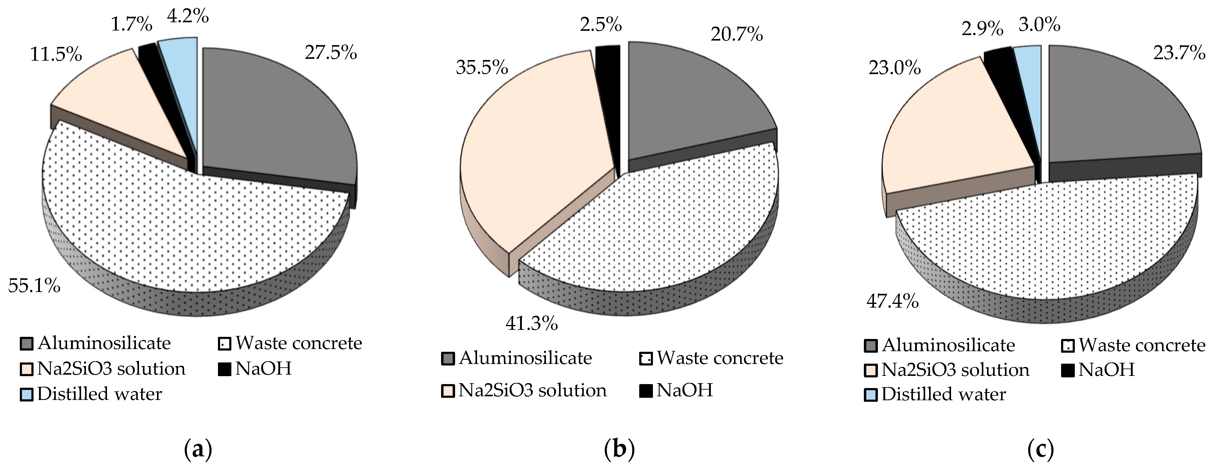
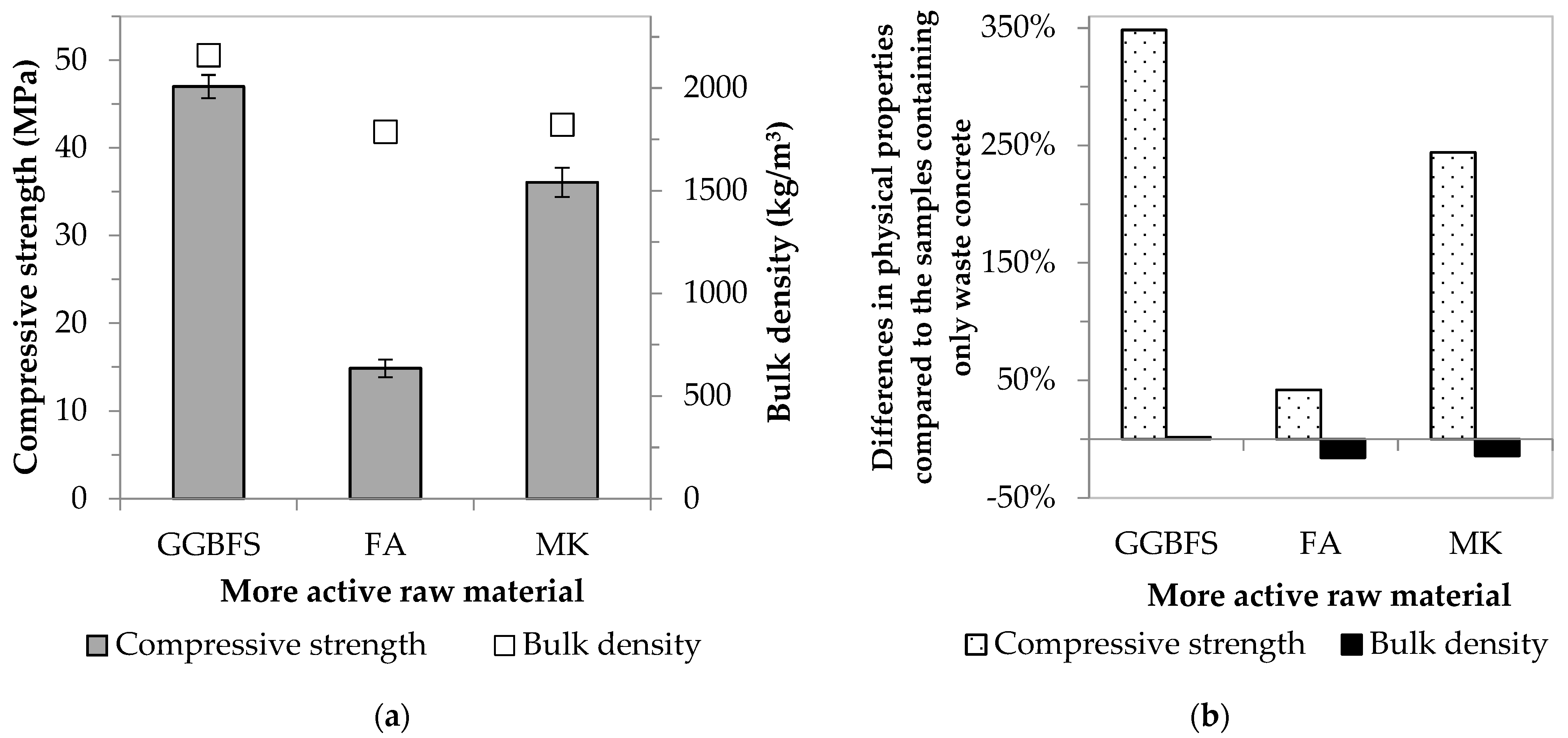
In the final phase of the mortar specimens test, AACs were produced by combining waste concrete with a particle size equal to the standard quartz sand and other more active raw materials (blast furnace slag, fly ash, and metakaolin). The SiO
2/Al
2O
3 molar ratio in the fly ash-based mixture was 8.8, the Na
2O/Al
2O
3 molar ratio was 1.9, the mass ratio of sodium silicate and sodium hydroxide in the activating solution was 14.3, and that of the activating solution and fly ash powder was 1.8. The following molar ratios were used in the metakaolin-based mixture: SiO
2/Al
2O
3 = 7.6, Na
2O/Al
2O
3 = 1.25, the mass ratio of Na
2SiO
3 to NaOH in the activating solution was 8.0, while the mass ratio of the activating solution to metakaolin powder was 1.2. The relative proportions of the components of the AAC samples prepared by combining the three different aluminosilicate sources and waste concrete are shown in
Figure 2. The experimental parameters for each series of “dense” AACs are shown in
Table 7.
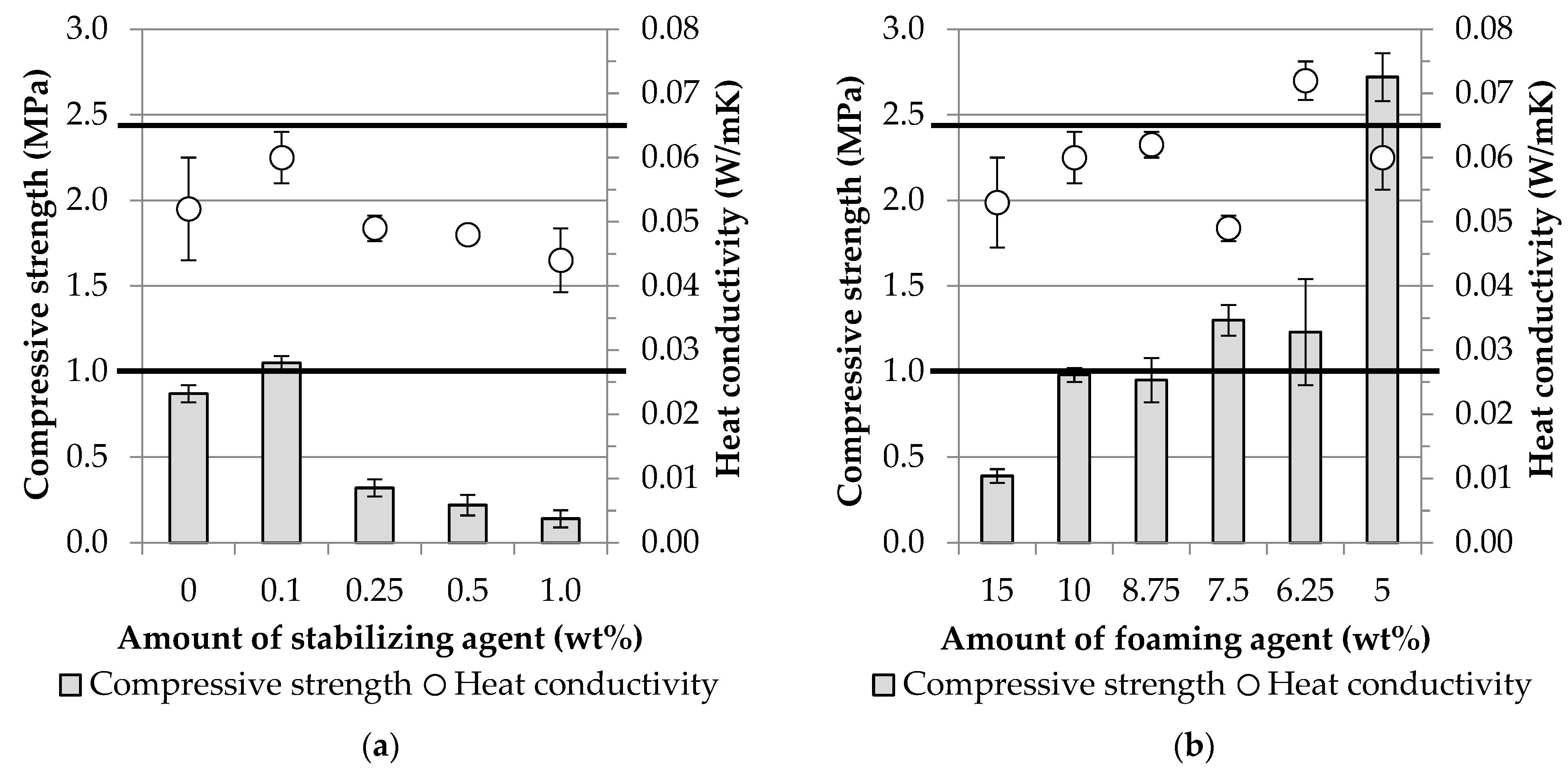
In the second phase of the experimental work, foamed AAC specimens were prepared from the optimal mixtures of “dense” samples. The required amount of the foaming components (stabilizing agent and foaming agent) was determined in the case of GGBFS-waste concrete-based AAC. First, the amount of H2O2 solution (10 wt%) was fixed, and the stabilizer content (0, 0.1, 0.25, 0.5, and 1 wt% based on the weight of the AAC slurry (slag + concrete + activating solution)) was varied. The second time, taking into account the relevant physical properties, the sodium oleate content was fixed (0.1 wt%) and the amount of foaming agent was varied (15, 10, 8.75, 7.5, 6.75, and 5 wt%).
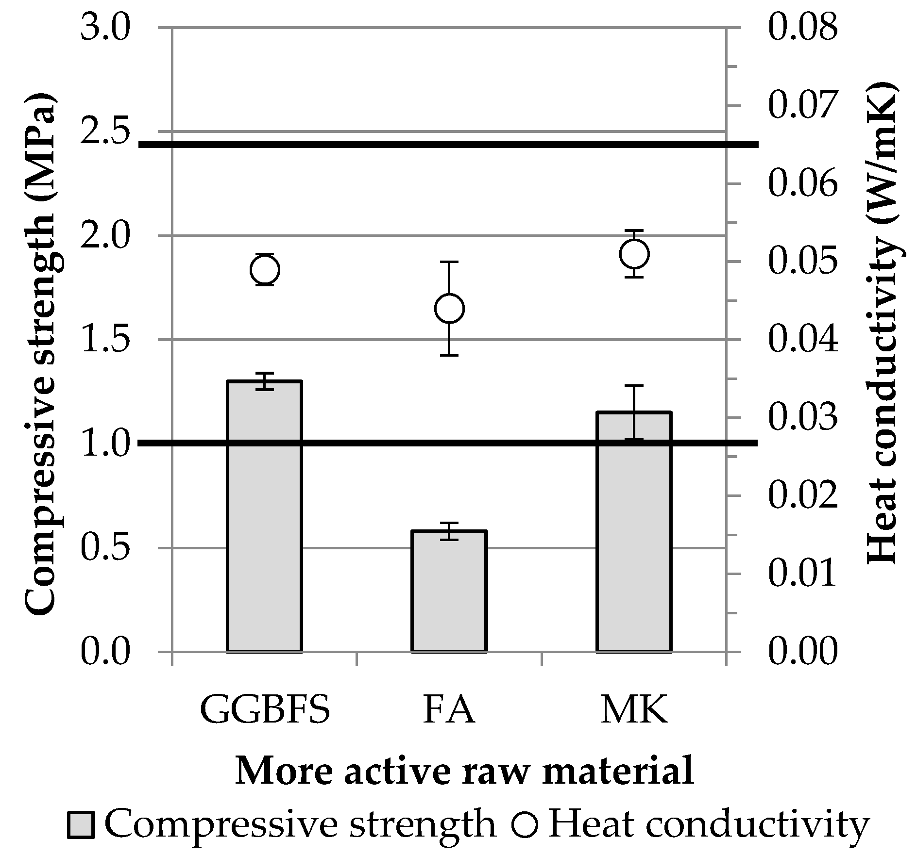
In the case of the foamed products, as with the “dense” specimens, the effect of the combination of more active raw materials and waste concrete on the physical properties was investigated. Accordingly, in parallel to the slag-based mixtures, fly ash and metakaolin-based foamed AAC specimens were produced using 0.1 wt% sodium-oleate and 7.5 wt% H2O2 solution.
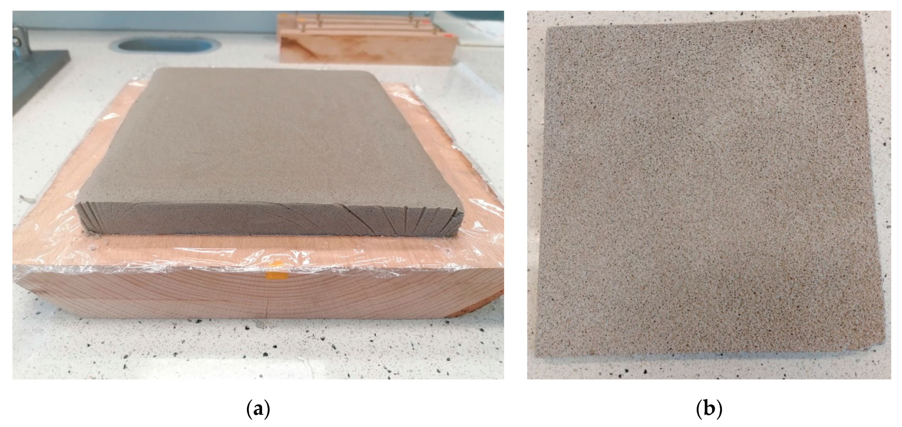
Finally, the potential to create GGBFS—waste concrete-based foamed products on a larger size was investigated, with the green economy and zero-waste approach in mind. On the one hand, samples of dimensions 200 mm × 200 mm × 15 mm were prepared (for thermal conductivity measurement using the longitudinal heat flow meter method), and on the other hand, test specimens of dimensions 40 mm × 40 mm × 160 mm were prepared in accordance with the standard specifications used for cements (EN 196-1). The experiments for the foamed AACs, as in the case of the “dense” samples, consisted of several series, the details of which are shown in
Table 8.
2.3. Methods
Qualitative and quantitative phase analyses of the aluminosilicate sources and waste concrete powder were carried out using a Philips PW 3710 type X-ray diffractometer with CuKα radiation (50 kV, 40 mA), graphite monochromator, and 0.02° 2Θ/s speed (in the 2Θ range, 10–70°). The X’Pert Data Collector software (version 2.2) was used to control the device and collect data. An internal standard method was used to determine the amounts of crystalline phases and the amorphous fraction. In the process, 0.1000 g of ZnO was added to 0.9000 g of powdered sample (maximum particle size < 63 μm). In order to avoid orientation, back-loaded samples were used in the tests. The evaluation of X-ray diffractograms and the implementation of Rietveld analysis were carried out with the help of X’Pert Highscore Plus and the ICDD PDF-2 reference database.
The chemical composition of the starting materials (GGBFS, FA, MK, and WC) was determined using a Philips Axios PW 4400/24 type wavelength-dispersive X-ray fluorescence analyzer with melt sample preparation (sample/solvent mass ratio = 1.8, solvent: Li2B4O7 + LiBO2) according to the EN 196-2:2013 standard.
The particle size distribution of GGBFS, FA, and MK and their median (D50) were determined using a Fritsch Laser Particle Sizer “Analysette 22”-type laser granulometer. The measuring range of the device is 0.1–1160 μm, the total measurement time is two minutes, and the red He-Ne laser beam used has a wavelength of 632.8 nm and a power of <3 mW. The required sample amount (0.5–1.0 g) was loaded manually, taking into account the appropriate feedback from the instrument (the optimum sample amount was indicated by the change of the scale color from red to green). In order to achieve appropriate dispersion and prevent intergranular aggregation prior to the start of the measurements, the samples were treated in a water bath equipped with an ultrasonic stirrer and pump for 60 s.
The compressive strength of all AAC samples and the flexural strength of the standard-size foamed specimens were determined with the help of a CONTROLS Automax5 automatic double chamber device with an upper measuring limit of 15/300 kN in terms of load. The measurements were performed according to the relevant cement standard (EN196-1), using a loading rate of 2400 N/s for compressive strength and 50 N/s for flexural strength tests. In the case of compressive strength tests, however, the sample sizes differed from the standard (ø30 mm × 30 mm cylindrical samples were also tested in addition to standard-size specimens). Prior to the start of the test, the surfaces of cylindrical specimens were filed down perpendicular to the side. With respect to each mixture, three parallel measurements were performed, and the average strength values were reported.
The bulk density and open porosity of the foamed AAC samples were determined using the Archimedes method. The specimens were placed in distilled water and boiled for 2 h. After boiling, the test specimens were cooled, and then their water-saturated weight was measured with the help of a hydrostatic balance in air and through immersion in distilled water. The density of the liquid medium was 1000 kg/m3. With respect to each mixture, three parallel measurements were performed, and the average bulk density and open porosity values with standard deviation were reported.
The thermal conductivity of the AAC foams was determined using a non-equilibrium method, namely, the modified transient plane source method (MTPS), according to the requirements of the ASTM D7984 standard. To carry out the measurements, C-Therm TCi equipment was used, with a measurement range of 0.002–220 W/mK. Prior to the start of the test, the surfaces of the specimens were filed down flat, and the dust in the exposed pores was removed. The thermal conductivity of the larger (200 mm × 200 mm × 15 mm) samples made from the optimal mixture was determined using an equilibrium method, namely, the longitudinal heat flow meter method (ASTM C518), with the help of a NETZSCH HFM 436/3/1 Lambda device (measurement range: 0.002–1 W/mK, 0–100 °C). Before starting the measurements, the samples’ surfaces were filed down perpendicular to the side.
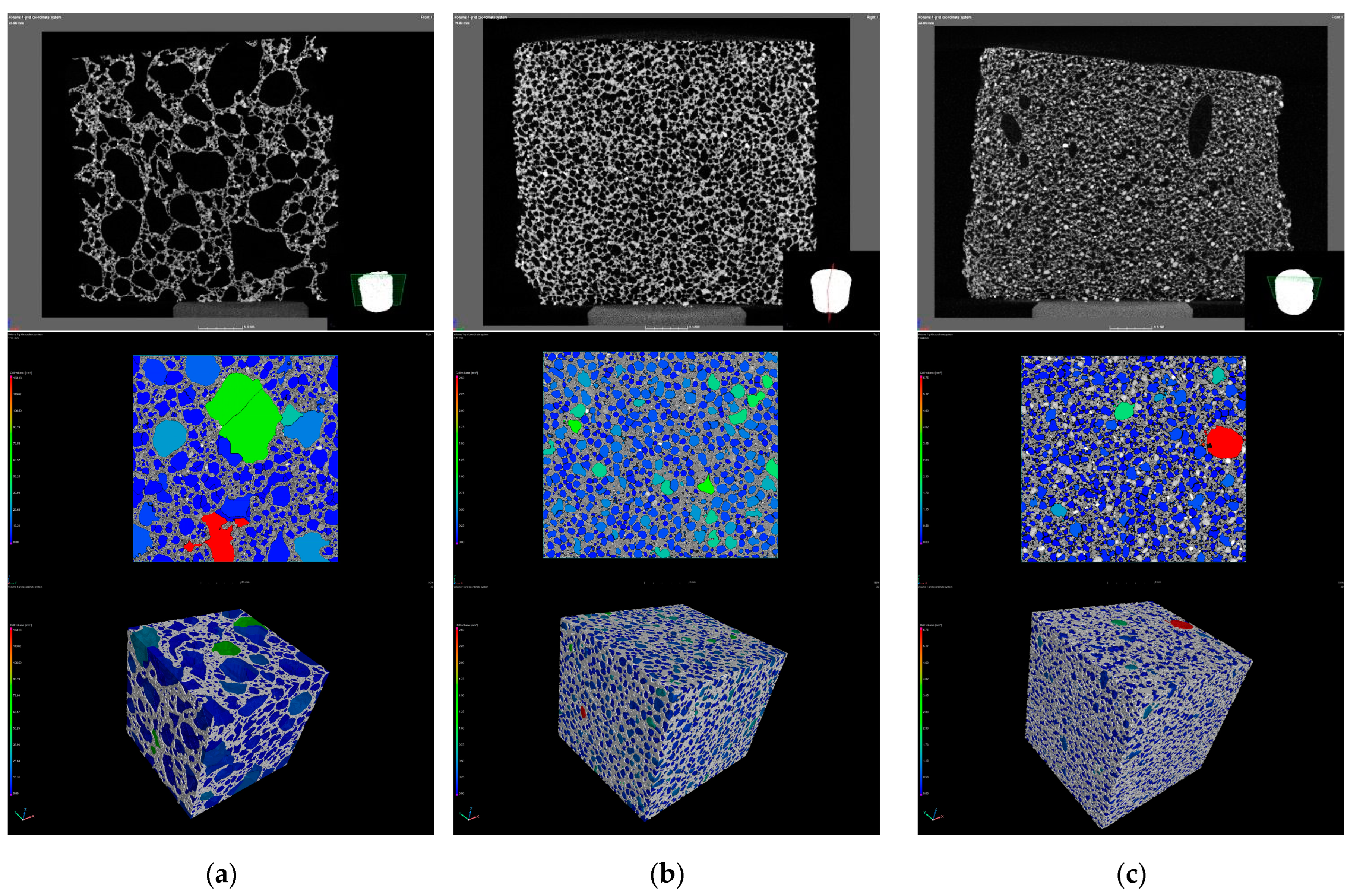
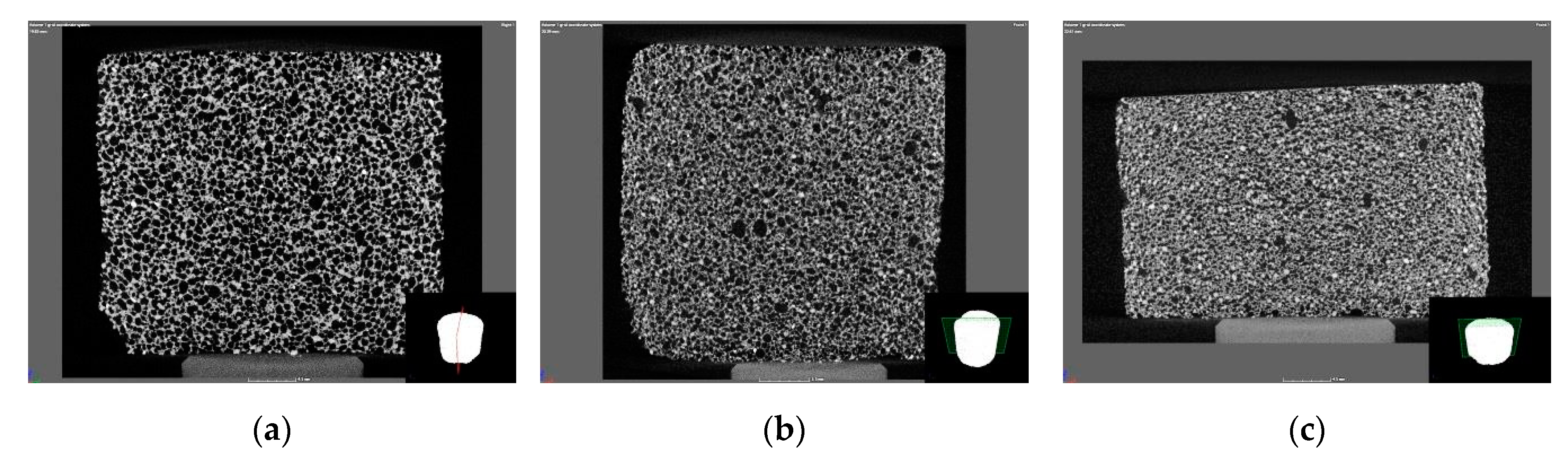
Computed tomography (CT) images of the foamed specimens were made with the help of a Nikon XT H 225 ST type X-ray tomography and the associated VG Studio 3.4 software. During the measurements, a cathode current of 85 μA and an accelerating voltage of 160 kV were used (1250 projections per recording, 2 recordings/projection, and 500 ms data collection time).


