Article

Morphological Analyses of W/Cu Functional Graded Materials Obtained by Conventional and Spark Plasma Sintering

by
Claudiu Nicolicescu
1,*,
Victor Horia Nicoară
1,
Cristina Ileana Pascu
1,*,
Ștefan Gheorghe
1,
Cristian Oliviu Burada
1,
Traian Florin Marinca
2 and
Florin Popa
2
1
Faculty of Mechanics, University of Craiova, 200512 Craiova, Romania
2
Faculty of Materials Engineering and Environment, Technical University of Cluj-Napoca, 400641 Cluj-Napoca, Romania
*
Authors to whom correspondence should be addressed.
Materials 2023, 16(11), 4126; https://doi.org/10.3390/ma16114126
Submission received: 29 April 2023 / Revised: 25 May 2023 / Accepted: 30 May 2023 / Published: 1 June 2023

Abstract

:
The paper presents the analysis of two compaction methods for obtaining W/Cu Functional Graded Materials (FGMs) consisting of three layers with the following compositions (% weight): first layer 80 W/20 Cu, second layer 75 W/25 Cu, and third layer 65 W/35 Cu. Each layer composition was obtained using powders obtained through mechanical milling. The two compaction methods were Spark Plasma Sintering (SPS) and Conventional Sintering (CS). The samples obtained after the SPS and CS were investigated from morphological (scanning electron microscopy-SEM) and compositional (energy dispersive X-ray spectroscopy-EDX) points of views. Additionally, the porosities and the densities of each layer in both cases were studied. It was found that the densities of the sample’s layers obtained through SPS are superior to those obtained through CS. The research emphasizes that, from a morphological point of view, the SPS process is recommended for W/Cu-FGMs, having raw materials as fine-graded powders against the CS process.

1. Introduction

Materials, energy, and modern sciences are the three great pillars of modern technology. In recent years, materials science has developed rapidly due to interdisciplinarity and due to new theories and technologies. The development of materials that respond to practical applications is of great interest, especially if their manufacturing technologies ensure low energy consumption and environmental protection [1].
Materials based on W/Cu are widely used for electrical contacts, heat sink materials for high-power microelectronic devices, welding electrodes, and thermal management devices [2,3]. Due to the lack of solubility between tungsten (W) and copper (Cu), these kinds of materials are difficult to produce.
There are several methods to produce W/Cu materials: by infiltrating the liquid copper into open pores of W skeleton and by liquid or solid phase sintering. The infiltration method requires higher consumption of energy, especially for complex shape parts, so it is very expensive [1,4]. An alternative for mixing W with Cu is mechanical milling. This approach was investigated in research [5] that showed the potential of the method.
Additionally, in ref. [6], research about obtaining W-Cu pseudo-alloys produced via powder injection molding (PIM) with powders prepared thermochemically is presented. By applying this treatment, the increase of the values of physical-mechanical properties of the final pieces was observed. In ref. [7], a novel approach to electric explosion of intertwined wires based on W-Cu powders and extrusion 3D printing was applied.
Besides a simple W/Cu mix, an improvement of this material class is obtaining functional graded materials. FGMs represent a class of materials composed of one or more different materials whose properties and structure vary throughout their volume. The component materials can vary chemically from metallic, ceramic, and polymeric materials to inorganic/organic materials, such as cells and tissues. A concrete example of biological materials with a structural and functional gradient is bones, teeth, and bamboo wood [8].
From a geometric point of view, the materials that make up an FGM can be in the form of lamella, granules, fibers, etc. [9].
Due to their high performance and many of their functionalities, FGMs have been successfully used in the construction of new generations of spacecraft. The most familiar FGMs are those composed of refractory ceramic materials and metals because they combine properties very well, such as resistance to high temperatures and wear and oxidation offered by ceramic materials with properties such as mechanical strength, machining, and toughness offered by metallic materials [10]. Due to their graded transition, another very important field of application of FGMs is that of ceramic coatings, where there is a need to reduce the stress concentrations and to increase the fracture strength [11,12,13,14].
W/Cu FGMs represent a class of materials which combine the properties of W such as high melting point, low coefficient of thermal expansion, and high mechanical resistance with those of copper, namely high electrical and thermal conductivity. Due to these properties, W/Cu FGMs are suitable for plasma-facing materials (PFM) for fusion reactors [15,16,17].
In the literature, there are some processes presented that are used for fabricating W/Cu FGMs, as follows: one-step resistance sintering method [17], laser sintering, vacuum plasma spraying (VPS) [14], chemical vapor deposition (CVD) [18,19], microwave sintering [20], and spark plasma sintering [21,22,23].
Within the methods used by the PM technique, plasma sintering (SPS) is one of the modern processes, which allows for the compaction and sintering of powders at the same time. It is a modern process with great potential [23,24], yet is rarely used in the manufacturing of W/Cu FGMs.
In ref. [25], experimental investigations on the Synthesis of W–Cu Nanocomposite through Spark Plasma Sintering were studied.
In ref. [26], elaboration and thermomechanical characterization of W/Cu Functionally Graded Materials produced by Spark Plasma Sintering for plasma-facing components are presented.
This study is focused on the W/Cu FGMs synthetized by SPS and CS, which were used as starting materials and mechanically milled powders, respectively.

2. Materials and Experimental Methods

2.1. Material Selections

In order to prepare W/Cu FGM, tungsten nanopowders (44 nm) and copper micron powders (type SE Pometon) were used. The particle size distribution of W nanopowders was determined by Dynamic Laser scattering (DLS), using a 90 Plus particle size analyzer, Brookhaven Instruments Corporation, Holtsville, NY, USA, equipped with 35 mW solid state laser, having 660 nm wavelength. The powder was in suspension with distilled water and the suspension was subjected to an ultrasound process for 5 min. Compared to SEM analysis, DLS measures the hydrodynamic diameter, which can be different because it depends on several factors such as the concentration of the dispersion medium, the type of ions in the dispersion medium, the size of the particles core, and the surface structure of the particles [27,28].
In Figure 1 and Table 1, particle size distributions of W nanopowders are shown.
As it can be seen in Figure 1a, on the volume distribution there are observed more bars which are not visible on the number distribution, Figure 1b. This means that there are particles which are agglomerate, but in a smaller volume. To avoid this phenomenon, it is better to increase the ultrasound time. From Table 1 it was observed that the particle size is equal to 43.7 nm.
In Figure 2, SEM images of the initial materials are presented. Tungsten nanopowders were obtained by mechanical milling for 35 h and, as it is observed in Figure 2a, these are agglomerated and have classical aspect of milled powders. Indeed, the powders consist of nanostructured particles that create larger particles. Additionally, the larger particles created by the nanopowders coexist with individual nanometric particles.
Copper powders, as seen in Figure 2b, have a dendritical shape due to the electrolytic process that was used in their production. The properties of the Cu powders are presented in Table 2.
Three types of mixtures with the following compositions—(% weight) 80 W/20 Cu, 75 W/25 Cu, and 65 W/35 Cu—were subjected to the mechanical milling (MM) process for 20 h in order to obtain composite powder used for preparing FGMs. For the MM process, a vario-planetary ball mill Pulverisette 4 made by Fritsch was used. The MM parameters were the following: the material of vials was stainless steel, vial volume was 250 mL, the material of the balls was stainless steels, the ball diameter was Φ = 10 mm, the balls to powder ratio was 2/1, the rotational speed of the main disk was 400 rpm, the rotational speed of the vials was 800 rpm, the milling atmosphere was argon, and the milling type was dry.

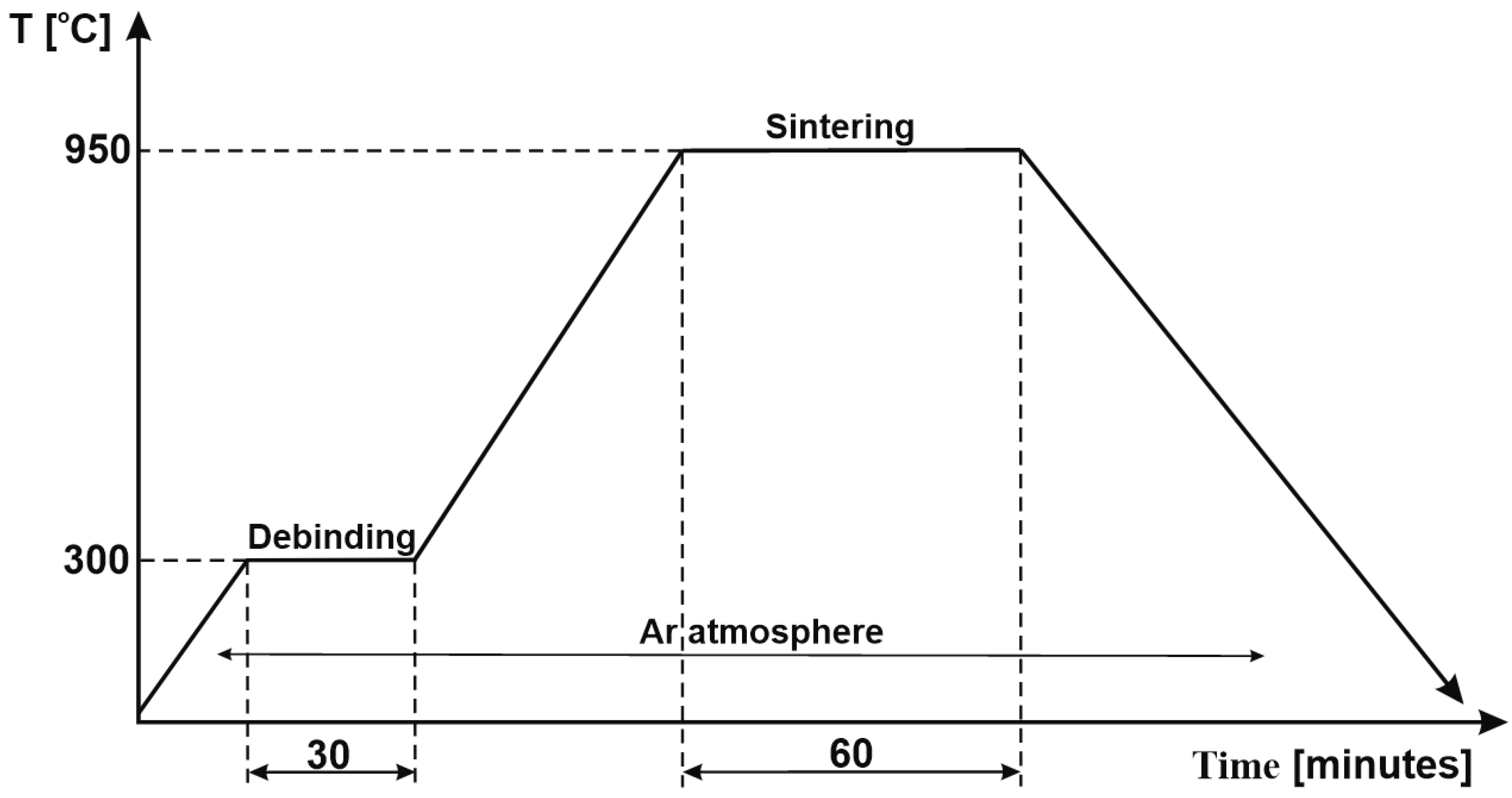
2.2. Experimental Procedure

The mixtures obtained after MM process were used to fabricate the FGM materials by SPS and CS, according to the flow chart presented in Figure 3.
For the SPS process the mixtures were stacked layer by layer into a graphite die (Φ = 20 mm) that was cylindrically shaped, according to Figure 3. A thin graphite paper was put between the punches and the powders to prevent the powders from sticking to it and to promote the electrical contact between the punch and powder. The sintering process was carried out according to the diagram given in Figure 4, with the following parameters: final temperature—950 °C; no dwell time; pressure—20 MPa; heating rate—300 °C/min.; current—10,000 A. The sintering parameters were chosen based on the temperature used for CS and it was performed with home-made SPS equipment from the Technical University of Cluj-Napoca. SPS installation operated at 24 V and 3.75 kA. Upon heating, the pulse ON time was 20 ms and the OFF-time was 20 ms.
In order to obtain W/Cu FGMs by CS process, the powders were stacked layer by layer into a metallic die (Φ = 12 mm) and were pressed at 600 MPa using LBG testing equipment, which was connected to the computer for registering the results by TCSoft2004Plus software. The force that was applied was equal to 68,293 Kn, the pressing speed was 50 mm/minute, and there was no dwell time at the higher force. In the first experiment, the powders were pressed without any lubricant addition and, because the particles were smaller (less than 500 nm), the green part had no mechanical strength (Figure 5a). Following these results, it was decided that the addition of a binder was necessary. A 2% weight of binder (paraffin) was added, resulting in the part with consistency (Figure 5b). This behavior was expected, as the powder was mechanically processed, and this procedure led to the loss of the powder plasticity, increasing the powder hardening. Additionally, the size of the particles has a great influence in the pressing process, the powders are fine, and the densification process demands a binder.
The CS process was carried out according to the diagram given in Figure 6 and consists of a debinding cycle of 30 min. The sintering cycle started at 950 °C with a dwell time equal to 60 min. The heating rate was 10 °C/minute and the cooling was slow, with the furnace (type: Nabertherm L3/11/C6). All cycles were carried out in an argon atmosphere.
The samples were axially cut using a Metkon Metacut-M 250 machine and were heat-mounted in transparent resin (30 mm diameter) using a Metkon Metapress-A machine. In order to study the microstructural aspects, the mounted samples were ground with silicon carbide papers with the following grits: 80, 120, 240, 400, 800, 1200, 2000, and 2500. They were polished with a GALAXY Polishing cloth PHI and Dia-Duo 2 suspension using Metkon Forcipol 2V machine. SEM characterization was performed using a JEOL JSM5600LV microscope equipped with an EDX spectrometer (Oxford Instruments, INCA 200 software).

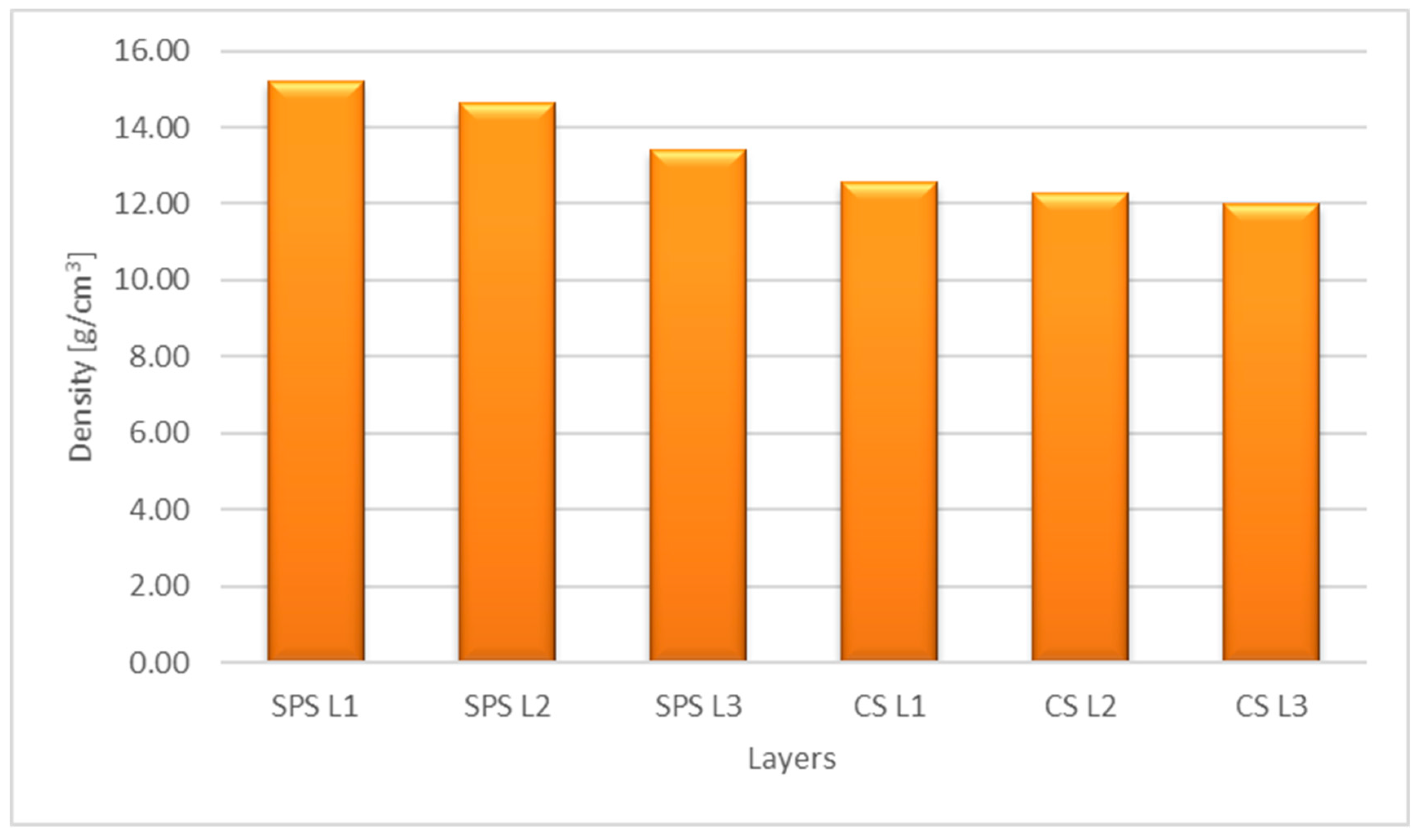
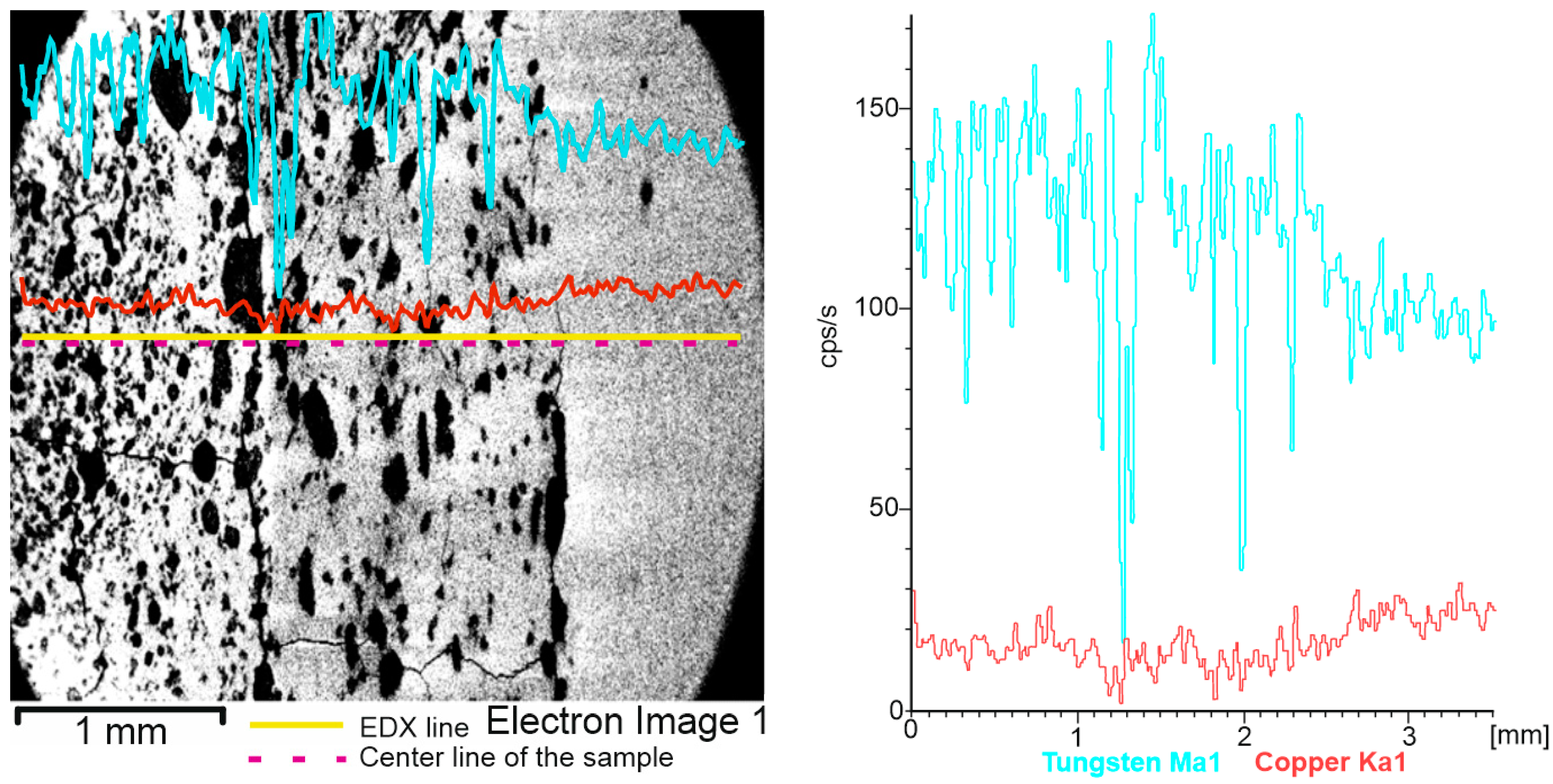
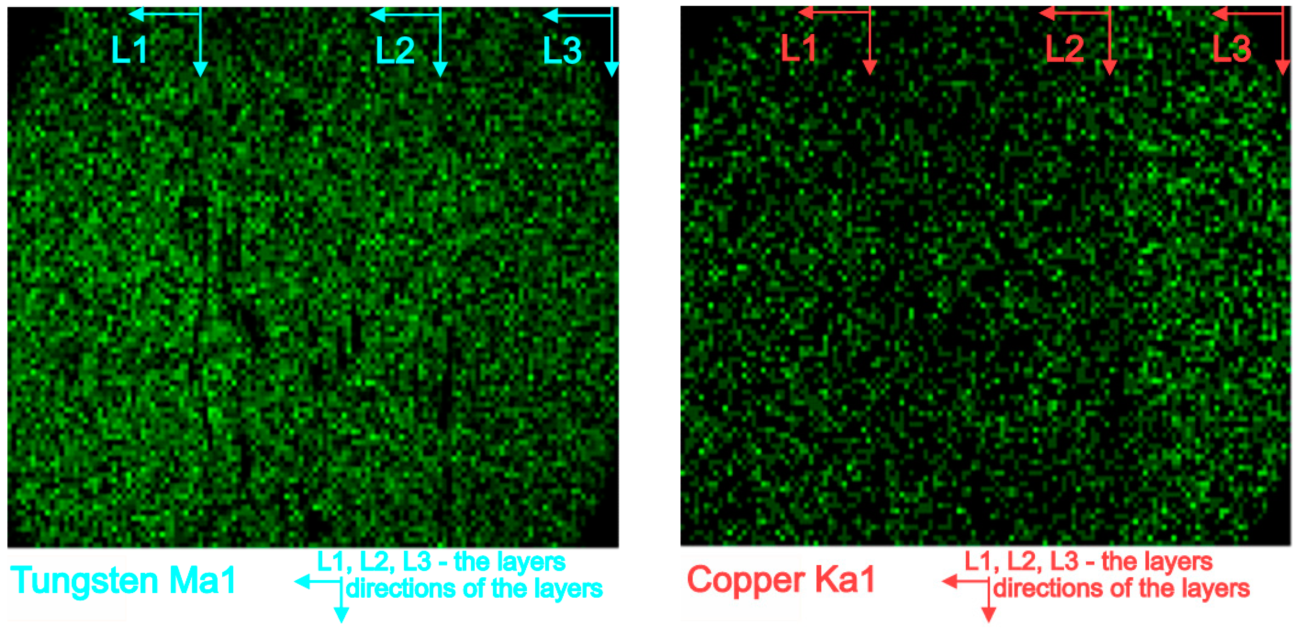
3. Experimental Results and Discussion

To determine the densities, the porosities of each layer were measured by image analysis using ImageJ software. In Figure 7, the porosities (P) of each layer for the two processes are presented, such as SPS (SPS L1—layer 1, SPS L2—layer 2, SPS L3—layer 3) and CS (CS L1—layer 1, CS L2—layer 2, CS L3—layer 3).
For each layer, the composition and theoretical density were determined by applying the following Equation:
Dc = DrVr + DmVm
where,
Dc—density of composite material; Dr—density of reinforcement material; Vr—volume fraction of reinforcement material; Dm—density of matrix material; Vm—volume fraction of matrix material.
In order to convert weight percentage to volume percentage, we applied the following equations:
V A = 100 1 + G B ρ A G A ρ B   [ % ]
V B = 100 1 + G A ρ B G B ρ A   [ % ]
where,
GA—% weight of tungsten; GB—% weight of copper; ρ A —density of tungsten; ρ B —density of copper; VA—% volume of tungsten; VB—% volume of copper.
Applying the Equations (1)–(3) and considering the density of W and Cu as 19.25 and 8.96 g/cm3, the theoretical density ( ρ t h ) of each layer was as follows: for layer 1 (80 W/20 Cu)—15.65 [g/cm3], for layer 2 (75 W/25 Cu)—14.96 [g/cm3], for layer 3 (65 W/35 Cu)—13.73 [g/cm3].
The densities were calculated according to the following Equation:
ρ = ρ t h 1 P 100   g c m 3
In Figure 8, the densities of each layer for the two processes, SPS and CS, are plotted.
As can be seen from Figure 7, a much lower porosity (average porosity of the three layers—2.41%) was attained for the sample sintered by the SPS process compared with the sample obtained by the CS process (average porosity of the three layers—16.67%). Being complementary with porosity, the density is higher for the sample obtained by the SPS process (Figure 8).
After milling together for 20 h, the morphologies of the three W/Cu compositions are shown in Figure 9.
As can be seen from Figure 9, the particles were homogenously dispersed for all the three mixtures. A good mixing of the components was achieved.
Figure 10 describes the line distribution of the cross-section W/Cu FGM, obtained by CS process. Tungsten content decreased from the first layer (left) to the third layer (right). Due to the porosity of the sample, the distribution of the hard component was affected by the material pores. On other hand, Cu acts as a binder and covers particles of W, leading to a smother distribution on the analyzed line.
Figure 11 shows the map’s distribution of the W and Cu elements of the cross-section of the W/Cu FGM obtained by CS, and Figure 12 shows the interface image of the three layers.
The distribution maps of W/Cu FGM obtained by CS, Figure 11, show some discontinuities due to the presence of cracks in the structure of each layer and interface, as can be seen in Figure 10 and Figure 12. The sample has large cracks and can be suitable for practical use if this structure, and other compaction methods, are suitable [29].
In the case of SPS sample, the EDX line distribution, as can be seen from Figure 13, shows the elemental content evolution of tungsten (W) and copper (Cu) as a function of the scanning distance. It was observed that the content of W decreases from the left (first layer—80%W) to the right (third layer—65%W). In Figure 14 the EDX map distributions for the cross-section of the three-layered W/Cu FGM are presented, and in Figure 15 the SEM images of interfaces obtained with the three layers are presented.
According to the maps, it was observed that the W and Cu phase are distributed relatively uniformly in each layer. Analyzing Figure 13 and Figure 14 and the compositions of each layer, it was concluded that the graded structure was attained, having the following dimensions of the layers: layer 1 = 1.17 mm, layer 2 = 1.18 mm, and layer 3 = 1.11 mm. The interfaces seem to present continuity from one layer to another. At a higher magnitude (over 1000×) there are no observed differences in the interface area, as can be seen in Figure 15.
Analyzing the distribution of elements and the images of the interfaces, it can be concluded that, using the SPS method, compact W/Cu FGM materials are obtained.

4. Conclusions

Functional graded materials based on W/Cu were successfully fabricated by the SPS process. To obtain green W/Cu FGMs by the CS method it is necessary to add binder, otherwise the green part of the sample has no mechanical strength. The elemental distribution maps of the samples obtained by SPS are more homogenous compared with the samples obtained by the CS process. In the cross-section of the CS samples, the presence of some dimples and cracks was observed, which are due to the pressing process. The cracks are presented in each layer, and in the interfaces. The CS process is time-consuming (~125 min until sintering temperature) compared to SPS sintering (~3 min). In contrast, through SPS a uniform and crack-free sample was obtained. It had lower porosity and high density. According to the morphological analysis, the SPS process is more suitable to obtain W/Cu FGMs compared with the CS process in the case of powders with fine granulation that are used as raw materials.

Author Contributions

Conceptualization, C.N. and V.H.N.; methodology, C.N., C.I.P., Ș.G. and V.H.N.; validation, C.N., T.F.M. and F.P.; formal analysis, C.I.P., C.O.B. and V.H.N. and investigation, C.N., T.F.M. and F.P.; writing—original draft preparation, C.N.; writing—review and editing, C.N., Ș.G., T.F.M., F.P. and C.O.B.; visualization, Ș.G., C.N., C.I.P. and F.P.; supervision, C.N. and C.I.P. All authors have read and agreed to the published version of the manuscript.

Funding

This research was funded by University of Craiova, 13 A.I. Cuza Street, RO-200585, Craiova, Romania and by the strategic grant POSDRU/159/1.5/S/133255, Project ID 133255 (2014), co-financed by the European Social Fund within the Sectorial Operational Program Human Resources Development 2007–2013.

Institutional Review Board Statement

Not applicable.

Informed Consent Statement

Not applicable.

Data Availability Statement

Not applicable.

Acknowledgments

The authors are grateful to the INCESA—Research Hub for Applied Sciences for advice and support.

Conflicts of Interest

The authors declare no conflict of interest.

References

  1. Pascu, C.I.; Stanimir, A.; Vida-Simiti, I. Research on the Manufacture of Some Tungsten-Copper Composite after Vacuum Sintering. Mater. Sci. Forum 2011, 672, 311–315. [Google Scholar] [CrossRef]
  2. Lee, Y.J.; Lee, B.-H.; Kim, G.-S.; Kim, D.-G.; Kim, D.-S.; Kim, Y.D. Evaluation of conductivity in W–Cu composites through the estimation of topological microstructures. Mater. Lett. 2006, 60, 2000–2003. [Google Scholar] [CrossRef]
  3. Kang, H.-K. Tungsten/copper composite plates prepared by modified powder in-tube method. Scr. Mater. 2004, 51, 473–477. [Google Scholar] [CrossRef]
  4. Da Costa, F.A.; da Sliva, A.G.P.; Umbelino Gomes, U. The influence of the dispersion technique on the characteristics of the W–Cu powders and on the sintering behaviour. Powder Technol. 2003, 134, 123–132. [Google Scholar] [CrossRef]
  5. Ding, F.; Fan, J.; Cao, L.; Wang, Q.; Li, J.; Li, P. Effect of Microstructure Refinement on Surface Morphology and Dynamic Mechanical Properties of W-Cu Alloys. Materials 2021, 14, 4615. [Google Scholar] [CrossRef] [PubMed]
  6. Ouyang, M.; Wang, C.; Zhang, H.; Liu, X. Effects of Bonding Treatment and Ball Milling onW-20 wt.% Cu Composite Powder for Injection Molding. Materials 2021, 14, 1897. [Google Scholar] [CrossRef] [PubMed]
  7. Lerner, M.; Suliz, K.; Pervikov, A.; Tarasov, S. Micron- and Nanosized Alloy Particles Made by Electric Explosion of W/Cu-Zn and W/Cu/Ni-Cr Intertwined Wires for 3D Extrusion Feedstock. Materials 2023, 16, 955. [Google Scholar] [CrossRef]
  8. Yin, B.; Sun, W.; Zhang, X.; Liew, K. Deciphering structural biological materials: Viewing from the mechanics perspective and their prospects. Compos. Part B Eng. 2022, 245, 110213. [Google Scholar] [CrossRef]
  9. Matějíček, J.; Musálek, R.; Dlabáček, Z.; Klevarová, V.; Kocmanová, L. Processing and Properties of Tungsten-Steel Composites and FGMs Prepared by Spark Plasma Sintering. Materials 2022, 15, 9037. [Google Scholar] [CrossRef]
  10. Leszek, C. Study on Strength and Stiffness of WC-Co-NiCr Graded Samples. Materials 2019, 12, 4166. [Google Scholar]
  11. Aleksander, Y.; Katarzyna, T.; Przemysław, Z. Use of Functionally Graded Material to Decrease Maximum Temperature of a Coating–Substrate System. Materials 2023, 16, 2265. [Google Scholar]
  12. Zhao, J.; Li, Y.; Ai, X. Analysis of transient thermal stress in sandwich plate with functionally graded coatings. Thin Solid Films 2008, 516, 7581–7587. [Google Scholar] [CrossRef]
  13. Sathish, M.; Radhika, N.; Saleh, B.A. critical review on functionally graded coatings: Methods, properties, and challenges. Compos. Part B Eng. 2021, 225, 109278. [Google Scholar] [CrossRef]
  14. Balci, M.N.; Dag, S. Solution of the dynamic frictional contact problem between a functionally graded coating and a moving cylindrical punch. Int. J. Solids Struct. 2019, 161, 267–281. [Google Scholar] [CrossRef]
  15. Chapa, J.; Reimanis, I. Modeling of thermal stresses in a graded Cu/W joint. J. Nucl. Mater. 2002, 303, 131–136. [Google Scholar] [CrossRef]
  16. Pintsuk, G.; Brünings, S.; Döring, J.-E.; Linke, J.; Smid, I.; Xue, L. Development of W/Cu—Functionally graded materials. Fusion Eng. Des. 2003, 66–68, 237–240. [Google Scholar] [CrossRef]
  17. Zhou, Z.-J.; Du, J.; Song, S.-X.; Zhong, Z.-H.; Ge, C.-C. Microstructural characterization of W/Cu functionally graded materials produced by a one-step resistance sintering method. J. Alloys Compd. 2007, 428, 146–150. [Google Scholar] [CrossRef]
  18. Thomas, G.; Vincent, R.; Matthews, G.; Dance, B.; Grant, P. Interface topography and residual stress distributions in W coatings for fusion armour applications. Mater. Sci. Eng. A 2008, 477, 35–42. [Google Scholar] [CrossRef]
  19. Chong, F.L.; Chen, J.L.; Li, J.G. Evaluation of tungsten coatings on CuCrZr and W/Cu FGM under high heat flux and HT-7 limiter plasma irradiation. J. Nucl. Mater. 2007, 363–365, 1201–1205. [Google Scholar] [CrossRef]
  20. Liu, R.; Hao, T.; Wang, K.; Zhang, T.; Wang, X.; Liu, C.; Fang, Q. Microwave sintering of W/Cu functionally graded materials. J. Nucl. Mater. 2012, 431, 196–201. [Google Scholar] [CrossRef]
  21. Tang, X.; Zhang, H.; Du, D.; Qu, D.; Hu, C.; Xie, R.; Feng, Y. Fabrication of W–Cu functionally graded material by spark plasma sintering method. Int. J. Refract. Met. Hard Mater. 2014, 42, 193–199. [Google Scholar]
  22. Yusefi, A.; Parvin, N. Fabrication of three-layered W-Cu functionally graded composite via spark plasma sintering. Fusion Eng. Des. 2017, 114, 196–202. [Google Scholar] [CrossRef]
  23. Wei, H.; Mei, J.; Xu, Y.; Zhang, X.; Li, J.; Xu, X.; Zhang, Y.; Wang, X.; Li, M. Low-Temperature Rapid Sintering of Dense Cubic Phase ZrW2−xMo2O8 Ceramics by Spark Plasma Sintering and Evaluation of Its Thermal Properties. Materials 2022, 15, 4650. [Google Scholar] [CrossRef] [PubMed]
  24. El-Hadek, M.A.; Kaytbay, S.H. Fracture Properties of SPS Tungsten Copper Powder Composites. Met. Mater. Trans. A 2013, 44, 544–551. [Google Scholar] [CrossRef]
  25. Elsayed, A.; Li, W.; El Kady, O.A.; Daoush, W.M.; Olevsky, E.A.; German, R.M. Experimental Investigations on the Synthesis of W–Cu Nanocomposite through Spark Plasma Sintering. J. Alloys Compd. 2015, 639, 373–380. [Google Scholar] [CrossRef]
  26. Autissier, E.; Richou, M.; Minier, L.; Gardarein, J.-L.; Bernard, F. Elaboration and Thermomechanical Characterization of W/Cu Functionally Graded Materials Produced by Spark Plasma Sintering for Plasma Facing Components. Fusion Eng. Des. 2015, 98–99, 1929–1932. [Google Scholar] [CrossRef]
  27. Lungu, M.; Tsakiris, V.; Enescu, E.; Pătroi, D.; Marinescu, V.; Tălpeanu, D.; Pavelescu, D.; Dumitrescu, G.; Radulian, A. Development of W-Cu-Ni Electrical Contact Materials with Enhanced Mechanical Properties by Spark Plasma Sintering Process. Acta Phys. Pol. A 2014, 125, 327–330. [Google Scholar] [CrossRef]
  28. Nicolicescu, C.; Nicoara, V.H.; Popa, F.; Marinca, T.F. Obtaining of W/Cu nanocomposite powders by high energy ball milling process. Mater. Res. Proc. 2018, 8, 173–181. [Google Scholar]
  29. Shagil, A.; Mohammad, S.; Mohd, R.M.; Manish, C.S. Recent Advancements in Powder Metallurgy: A Review. Mater. Today 2018, 5, 18649–18655. [Google Scholar]
Figure 1. Particle size distribution: (a) volume distribution; (b) number distribution.
Materials 16 04126 g001
Figure 2. SEM images of initial powders: (a) tungsten nanopowders; (b) copper powders.
Materials 16 04126 g002
Figure 3. Flow chart of operations for fabricating the FGMs.
Materials 16 04126 g003
Figure 4. SPS diagram.
Materials 16 04126 g004
Figure 5. Green W/Cu FGM: (a) without binder; (b) with 2% binder.
Materials 16 04126 g005
Figure 6. Conventional sintering diagram.
Materials 16 04126 g006
Figure 7. Porosities of the layers.
Materials 16 04126 g007
Figure 8. The layers densities after SPS and CS.
Materials 16 04126 g008
Figure 9. SEM images of the mechanically alloyed powders obtained after 20 h of MA: (a) 80 W/20 Cu; (b) 75 W/25 Cu; (c) 65 W/35 Cu.
Materials 16 04126 g009
Figure 10. EDX line distribution of W and Cu elements of the W/Cu FGM obtained by CS.
Materials 16 04126 g010
Figure 11. EDX map distribution of W and Cu elements of the W/Cu FGM obtained by CS.
Materials 16 04126 g011
Figure 12. SEM images of the interfaces of W/Cu FGM obtained by CS: (a) between layer 1 and layer 2; (b) between layer 2 and layer 3.
Materials 16 04126 g012
Figure 13. EDX line distribution of W and Cu elements of the W/Cu FGM obtained by SPS.
Materials 16 04126 g013
Figure 14. EDX elemental map distribution of W and Cu elements of the W/Cu FGM obtained by SPS.
Materials 16 04126 g014
Figure 15. SEM images of the interfaces of W/Cu FGM obtained by SPS: (a) between layer 1 (80 W/Cu) and layer 2 (75 W/Cu); (b) between layer 2 and layer 3 (65 W/Cu).
Materials 16 04126 g015
Table 1. Data of the particle size distribution.
d (nm)G (d)C (d)d (nm)G (d)C (d)d (nm)G (d)C (d)
31.100201.50991305.70100
36.800238.80991547.50100
43.7100992830991834.10100
51.8099335.401002173.70100
61.3099397.501002715.80100
72.7099471.101003084.80100
86.2099558.4010035040100
102.1099661.8010039800100
121099784.3010050830100
143.4099929.601006024.20100
1700991101.701007139.80100
Table 2. Properties of copper powder.
Physical Properties
PropertiesAdmitted ValuesStandard
Apparent density [g/cm3]2.30–2.50SR EN 23923-1/98
Flow time [sec/50 g]Max 40SR ISO 4490:2000
Chemical composition
ElementAdmitted ValuesStandard
CuMin. 99.7IL-08-0-94
O2Max 0.15SREN 24491-4:1994
Disclaimer/Publisher’s Note: The statements, opinions and data contained in all publications are solely those of the individual author(s) and contributor(s) and not of MDPI and/or the editor(s). MDPI and/or the editor(s) disclaim responsibility for any injury to people or property resulting from any ideas, methods, instructions or products referred to in the content.

