1. Introduction
Additive manufacturing is a type of manufacturing using special layer-laying techniques, allowing for the production of different shapes and forms [
1]. The main idea behind it is to reduce human labour and increase precision while also reducing waste [
2,
3,
4,
5]. There have been many attempts of introducing additive manufacturing, or so-called 3D printing (3DP), into the scientific and engineering world, and each used a different approach. Besides changing layer-laying techniques, there have been attempts of using a large variety of materials [
2,
3,
5,
6,
7]. While materials such as polymers promptly gained popularity because of their highly plastic behaviour and ease of forming, more rigid materials such as concrete, mortar, or clay were not in favour [
3,
6,
8,
9]. Notably, 3DP technologies brought a new level of freedom of form and shape into the building industry [
4,
5,
10,
11]. The lack of need for external formwork not only allows designers to change the design of certain elements to a more sophisticated and complicated one, but it also cuts costs by up to 54%. It is estimated that 34% of the cost of rising monolithic construction results from the formwork itself, and an additional 20% is generated by the work needed for its use and maintenance [
2,
7,
12]. The use of programmed machines allows for excluding man-made errors and continuous operation in a building site [
2,
3,
6,
10].
Although there are a few 3DP methods [
13], and quite a substantial number of material mixtures are used in different methods and different ideas of reinforcement, there is still not enough information about how printed materials behave, and what possibilities of improvement there are [
3,
5,
10,
14]. Each method of printing has its flaws. Binder-jetting and D-shape printing techniques, while offering the huge advantage of free forming, need after-treatment, which takes time and a lot of additional labour [
15,
16]. Contour crafting (CC) and concrete printing (CP), while giving good results in buildability, have problems with maintaining overhangs and elements such as lintels, which have to be added separately [
2,
17]. What is important is that most of the materials used in 3D printing have inferior thermal capabilities, which limits the use of this technology in colder and more harsh environments. Besides changing the structure of elements so that they obtain better thermal capabilities [
18], there are ideas of using different materials to insulate the structures by adding them as a layer inside of elements or changing the thermal behaviour of the main printing material by changing its mixture composition [
3,
19]. The addition of foam insulation inside 3D-printed concrete elements might work as in the case of sandwich composites, where structures with concrete outer shells and foam cores will be lighter than monolithic concrete structures while still maintaining considerable strength and additional thermal properties [
20,
21]. Materials can be also designed to be functionally graded (FG), which means that the material’s properties change stepwise in a sequence of layers or according to desired gradient [
21,
22]. To increase the building capabilities of CP, there have been attempts of adding reinforcement to printed layers via the addition of fibre reinforcement [
13,
23] into the material mixture, the addition of continuous reinforcement between the printed layers [
2,
3,
24], or even with the use of nails [
25].
Even though there are mixtures used for 3D printing, which should be able to withstand 80 MPa in uniaxial compression tests after curing, most of them are mortars or low-grain concrete mixtures rather than actual concrete mixtures [
26,
27,
28]. In other words, most of the mixtures used in CP technology do not contain coarse aggregates, and therefore they do not count as regular concrete mixtures. The use of coarse aggregates is problematic in CP because of the risk of jamming the machine during the process and the high risk of a structure being uneven, which might lower the strength of the bond between layers [
5]. The use of low-density materials such as cork granules, which are mostly by-product waste, as additional filler might be the solution to this problem [
29,
30]. Due to the porous structure of natural cork, not only is it light but it also has good thermal properties, which might positively impact the final mixture’s properties [
31,
32,
33]. Therefore, the current important problem is to explore highly renewable and ecological materials such as cork, not only to improve the materials used in the building industry but also to make 3DP technology more viable and available for future generations.
Moreover, 3DP technology should be continuously optimised. Different ways of mixture extrusion might have an impact on printing times and the precision of the final product [
2,
6]. The influence of changes in the concrete mixtures such as additives and admixtures, water-to-cement ratio, the use of different aggregates, and fibre reinforcement can have a serious impact on the behaviour of printed elements [
15,
34,
35,
36]. Because of the well-known facts of the positive impact of continuous reinforcement on concrete structures, continuous reinforcement in 3D-printable forms should be taken into consideration as an inseparable part of the whole process [
5,
7,
37].
Therefore, in this study, we explore the properties of a new CP method containing three additional phases. Besides the use of novel extrusion machines based on the ideas of popular CP machines, a 3D-printable composite material containing cork granules as aggregate and two types of reinforcement in the form of polypropylene fibres and a continuous polyethylene net were used [
7,
17,
38]. The main mixture of CP composite was based on a few earlier studies and was adjusted for the capabilities of available equipment.
2. Materials
The final mixture was prepared using materials such as cement, sand, granulated cork, water, additives, and reinforcements. The amount of every material was adjusted to achieve the mixed properties necessary for the extrusion of the material. Properties such as extrudability, flowability, buildability, and open time were taken into account. It should be stated that we initially used gravel with a maximum dimension of 4 mm as the main source of coarse aggregate, but due to its properties leading to the reoccurring high risk of machine jams, the use of gravel was discontinued.
EN 197-1 CEM I 42,5 R Portland cement was used as the matrix. Silica sand was used as the main source of fine aggregates. Granulated cork with a maximum diameter of 3 mm was used as a lightweight aggregate. Cork was chosen because of its good thermal properties and low density, as stated in [
19]. The used aggregates and the grading curves of their composition are shown in
Table 1. Tap water was used as a source of batched water.
Figure 1 shows a comparison of the aggregates and their composition’s grading curves.
Plasticising and aerating admixtures were added to lower the need for the use of water in the proposed mix and increase its frost resistance. The fluid admixture should be added to water in batches, amounting to 0.3% to 0.6% of the mass of added cement. The properties of the admixture declared by the manufacturer are shown in
Table 2.
Fib-34, class 1a, and 12 mm polypropylene fibres were used to minimise the influence of contraction during curing and to facilitate the stabilisation of the mix throughout the whole process of specimen preparation. According to the manufacturer, 0.003% to 0.006% of fibres shall be added for every kilogram of cement in the mixture. The number of fibres should be adjusted according to needs and equipment capabilities.
A polyethylene monofilament net with a 7 × 7 mm size of mesh was used as the source of main reinforcement. No additional coatings were applied on the net before its implementation in the structure of the composite. Besides being weather- and water-resistant, polyethylene has low reactivity, which allows for its use in different aggressive environments. In addition to that, its non-magnetic nature enables its use in places where magnetic fields might produce risks for the use of standard reinforcement. Because of the high popularity of the material itself, it should not be a problem to manufacture nets suitable for special use in 3D printing. The use of nets as reinforcement in 3D-printed elements can lower slumping effects and minimise the so-called elephant’s foot effect of lower layers. A mix of sand and granulated cork in a specific ratio was prepared to cover the need for aggregates. During the process of obtaining the final mixture, gravel use was discontinued because of its capability to jam the machinery. Part of the mixture that should be covered by gravel was substituted by sand in an equal amount. The water-to-binder ratio of the mixture was set at 0.48. This ratio is not far off the commonly proposed for 3D-printable mixtures [
7,
17,
21,
27,
39]. Although the ratios are different from commonly used ones, the water-to-cement ratio used in this mixture allows for the easy extrusion of material, in addition, it should be stated that a lower ratio is preferable and more beneficial for 3DP processes. The final composition is shown in
Table 3.
Although the grading curve of the composition of aggregates does not perfectly match the lower and upper limits presented by PN-B-06712:1997, [
40], having a high number of particles with a size of 0.25 mm or larger and fewer particles smaller than that size substantially lowers the water demand of the mix. The use of aggregates smaller than 4 mm allows for the use of the mixture in the extrusion process.
A special mixing procedure was carried out before the extrusion of the material. All of the components have to be properly weighed before further steps. After the preparation of the components for the needed amount of mixture, one should proceed with a preliminary mix of dry components. Cement, sand, cork granules, and polyethylene fibres should be mixed until uniform coverage of all the ingredients with cement. For better fibre distribution in the mix, it is suggested to add the first half of the prepared fibres at the beginning of dry mixing and the second half, halfway through. In the next step, half of the prepared water and all of the admixture should be added to the dry mix and mixed mechanically for about 2 min until components are spread uniformly, and consistency of the mixture is achieved. After 2 min of mixing, even if the expected effect is not achieved, the rest of the water should be added, and all of the mixtures should be mixed for 3 min clockwise and 3 min in the opposite direction. The effects of longer mixing times are not known, but it has been established that mixing times lower than a total of 6 min significantly worsen the spread of mixture components, which leads to imperfections in the fresh mixture and this in turn leads to imperfections in cured elements.
Fresh mixtures have to be subjected to preparation time, which consists of leaving the fresh mixture for 20 min at room temperature and humidity. After the first 10 min of preparation time, the fresh mixture should be stirred thoroughly. The mixing material that stayed on the walls of the container with stirred material should be taken into consideration. When the point of 20 min of preparation time is reached, the fresh mixture should be stirred again and used for specimen preparation. The processed mixture is usable for about 80 min, and after that period, it is prone to cause extrusion system blockage.
4. Results and Discussion
4.1. Measurements, Observations, and Calculations
Table 4 collects the physical properties of the specimens measured before machining.
The data listed in the above tables allow for defining certain characteristics of the material used in the chosen 3DP technology. The material was characterised by high water absorption, which is probably related to the use of granulated natural cork as lightweight aggregate. There were no significant differences between the amount of water absorbed by specimens with and without continuous reinforcement (WCR), so continuous reinforcement was not correlated with high water absorption and did not have a negative impact on this property. If continuous reinforcement had any effect, it would be visible as higher or lower water absorption values, but due to the lack of changes, one can assume a lack of correlation.
Although identical printing methods and materials were used for specimen production, there were slight differences between the specimens’ dimensions and structure. The use of continuous reinforcement during specimen production facilitates the form retention of each layer, highly improves the material’s buildability, and reduces the so-called elephant’s foot effect of lower layers. The changed dimension values of the specimens after their machining for the 3PB test were later used for calculations. Additional information about the use of continuous reinforcement and its impact on the quality of the interlayer connection was gathered during the process of destruction. No voids or air pockets were found between the net or near the net’s structure, and layers were firmly connected.
4.2. Freeze–Thaw Test
There were no visible changes in the mass and geometrical aspects of the specimens. Further mechanical tests were conducted to measure the eventual changes in the specimens.
4.3. Three-Point Bending (3PB) Test
The test results and the calculated values are shown in
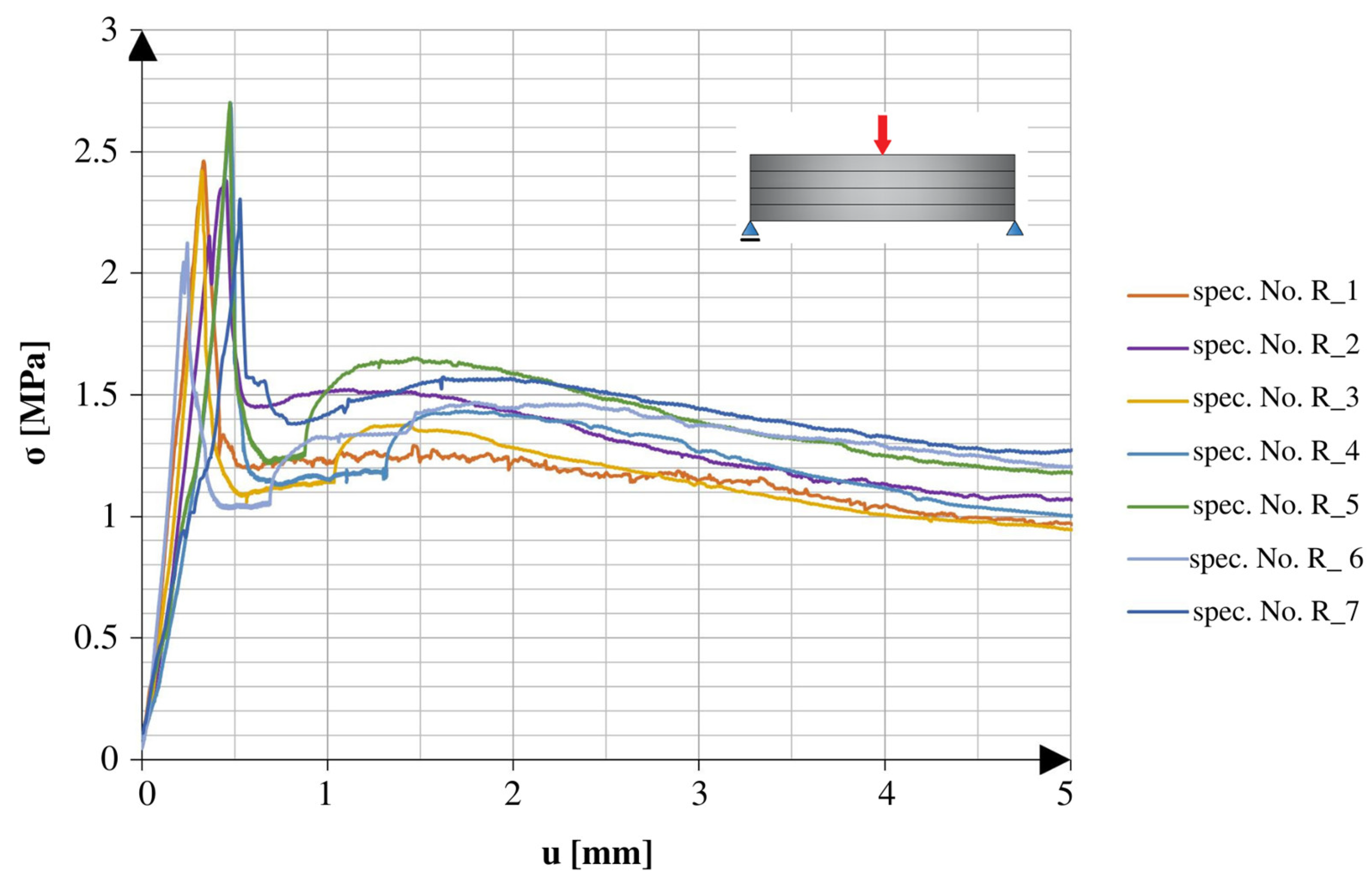
Table 5. The specimens tested for frost resistance are marked by the letter R. The material tested for frost resistance showed a 1.0% loss of strength in the 3PB tests.
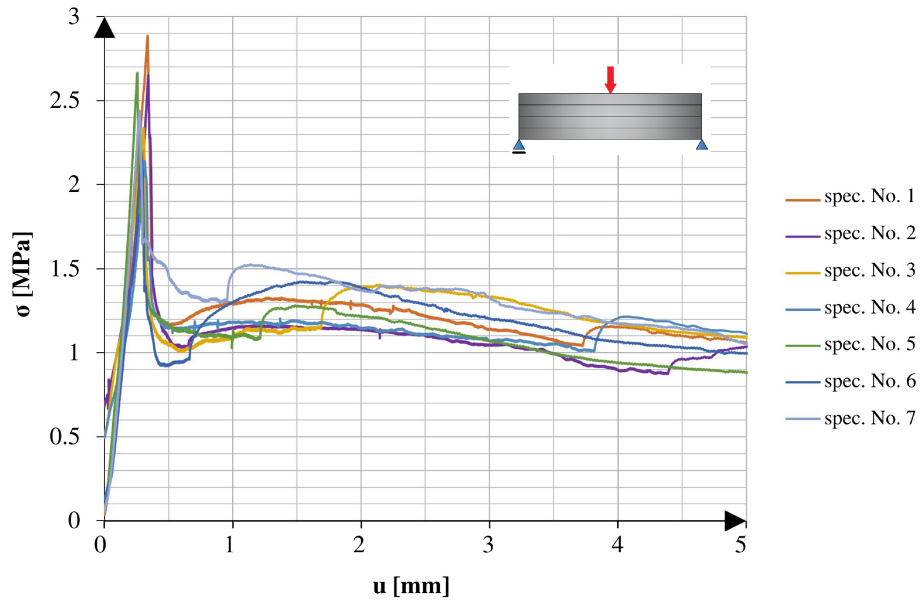
Figure 6 shows a comparison of the loading graphs plotted for the early stage of the 3PB tests of the specimens with continuous reinforcement cured at room temperature.
Figure 7 shows a comparison of the loading graphs plotted for the early stage of the tests using the specimens with continuous reinforcement and 25 freeze–thaw cycles.
Both types of specimens showed similar behaviour throughout the test. At the beginning of the test, as displacement increased, the applied force increased until reaching a critical point. The critical point indicated the force of failure, which was the maximum force the specimen could withstand. After that critical point, there was a fast drop in the applied force to about 50% of the critical point value, which did not change for a while. The lack of change, reflected in the plateau of the graph, changed after another smaller peak, which led to lower forces with the tendency of aiming at 0 N.
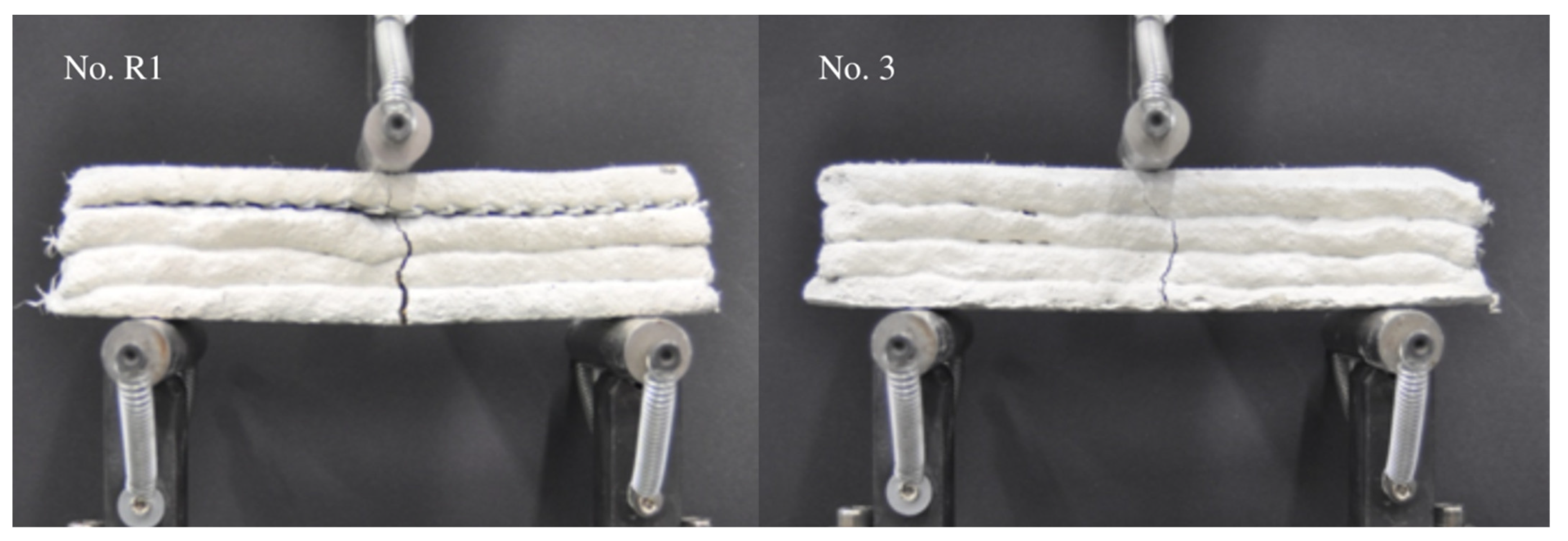
The shape of destruction, which is probably related to the shape of the tested specimens, imperfections of their interlayers, and the distribution of cork granules in the volume of the specimens, is shown in
Figure 8. The relatively low final strength, considering the high amount of cement used in the mixture, might be because the material was not compacted during the process of extrusion, as well as due to the addition of cork, which worked as the weak point in the structure [
29,
30,
45].
4.4. Uniaxial Compression Test
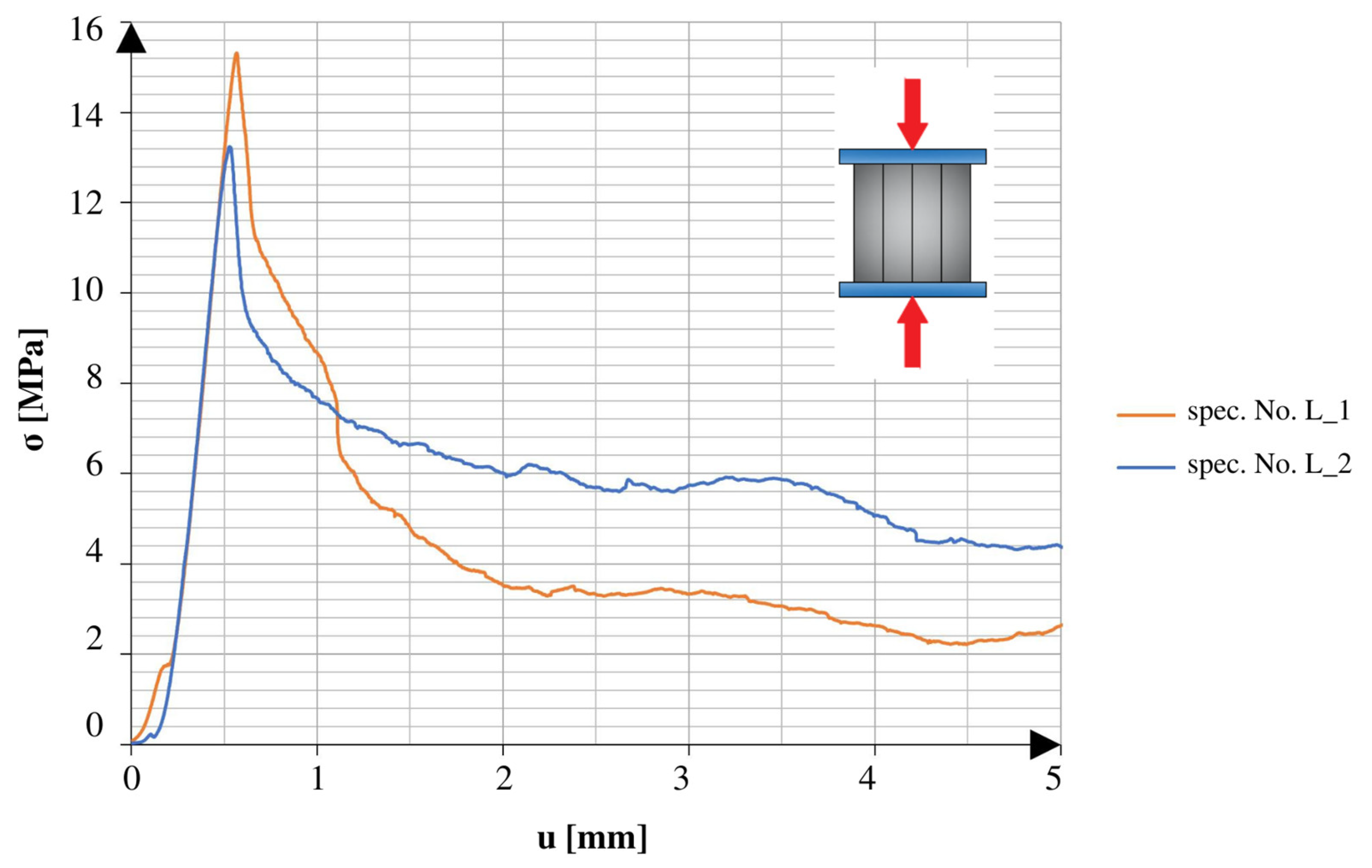
Table 6 shows the test results and the calculated values for the specimens tested under uniaxial compression. The specimens after 25 freeze–thaw cycles are marked by “M”, and the specimens with the net reinforcement are marked by “Z”. “H” indicates that the specimen was tested along the axis of the specimen’s height, and the specimens tested along the axis of their length are marked by “L”. Four additional specimens without net reinforcement were tested to obtain information about how the applied reinforcement worked with the used materials.
There was a marked difference between the obtained results of the specimens tested in different directions. The specimens tested in the direction of the height axis showed a quick peak in the applied force, which later rapidly decreased to the smaller residual values. The specimens compressed in the direction of the length axis showed similarities to the specimens tested under the 3PB test. After reaching the point of failure, these specimens maintained a certain amount of strength, which continued until reaching another peak, followed by a rapid decrease in values. The specimens tested after 25 freeze–thaw cycles had similar tendencies in both directions of compression. All of the graphs show the early stage of loading. In addition to the changes observed in the graphs, it should also be noted that the obtained maximum values varied relative to different directions and aspects of the specimens.
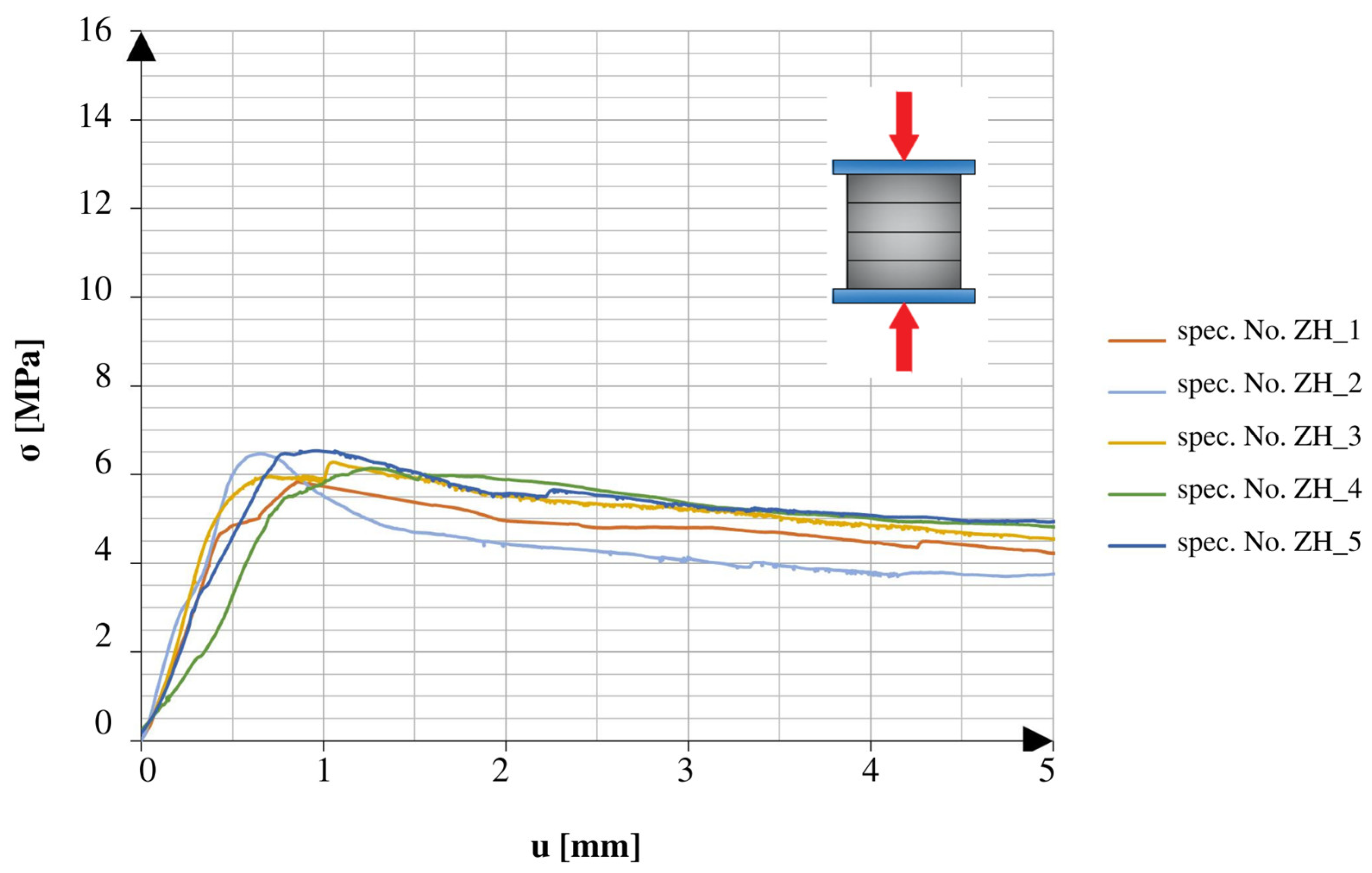
Figure 9 and
Figure 10 show a comparison of the graphs plotted for the specimens with net reinforcement and without additional testing for frost resistance. For the specimens without additional heat treatment, a typical difference in the obtained strength value in different compression directions was 42.6%. Similar to the results acquired during the 3PB test, the relatively low final strength might be related to the lack of compact material and the addition of cork.
Figure 11 and
Figure 12 show a comparison of the graphs obtained from the tests of the specimens without net reinforcement. Differences of 28.8% were observed between the results obtained in different directions of testing. In comparison to the standard specimens reinforced with the net, the specimens without net reinforcement on average obtained 38.5% higher strength values for compression along the height direction and 23.8% higher values for compression along the length direction.
Figure 13 and
Figure 14 compare the graphs obtained from the tests using the specimens with net reinforcement that also underwent 25 freeze–thaw cycles. After 25 freeze–thaw cycles, a difference in value of 42.9% was observed. The specimens treated with 25 freeze–thaw cycles showed 11.2% higher strength values in the height direction and 11.8% higher values in the length direction than the specimens without heat treatment. The counterintuitive behaviour of the composite might be related to differences in the internal structure of the specimens, which could not be observed during external visual tests. Moreover, the authors hypothesise that the changes in the internal structure caused by the formation of microcracks in the material during multiple cycles of freezing and thawing might have led to better energy transfer between the layers. Thus, the increase in strength during the uniaxial compression test may be associated with higher energy dispersion. The change in behaviour seen during the 3PB test was related to a different type of destruction process.
Figure 15a,b show different final failure modes of the specimens relative to different orientations of the layers (H—horizontal and L—longitudinal) under the compression force. In the case of the specimens tested in the direction of their height (
Figure 15a), chipping and cracking were distributed over the whole composite volume, through all layers. The destruction of the specimens compressed in the direction of the specimens’ length (
Figure 15b) mainly consisted of the splitting of layers and additional horizontal cracking, enhancing this separation process.
Figure 16 shows a comparison of the obtained averaged values of failure stress with standard deviations for different series of specimens and tests. For easier data reading, the series tested for compression are marked with the letter “C”, and the series used for the three-point flexural test are marked with “FLEX”. All other markings are similar to those used in
Section 4.3 and
Section 4.4.


