
Numerical Analysis, Optimization, and Multi-Criteria Design of Vacuum Insulated Glass Composite Panels
 , , , and
Abstract
:1. Introduction
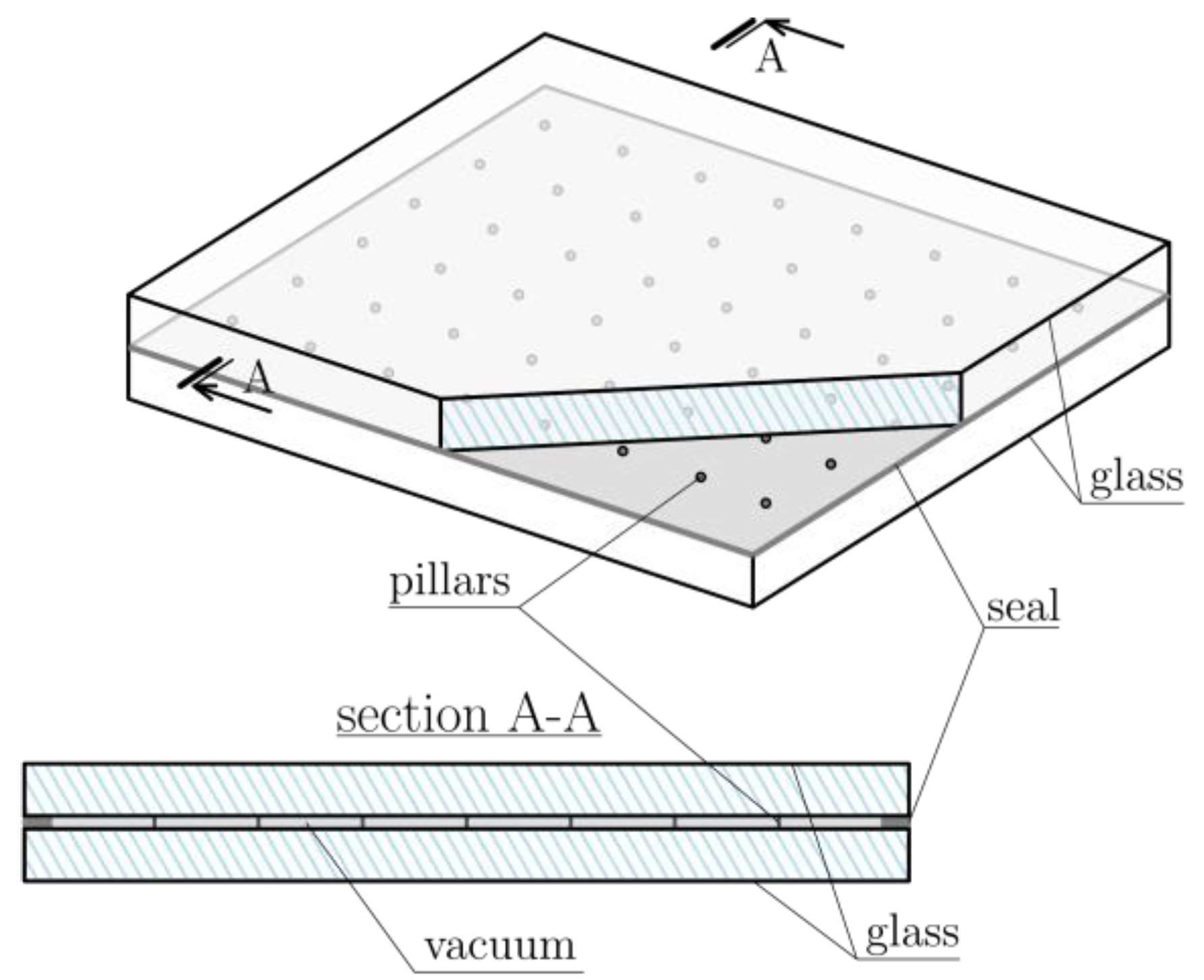
1.1. VIG Panels
1.2. Fractals in Engineering
1.3. Motivation
1.4. Purpose of the Work
2. Numerical Modelling
2.1. Geometry and Support Conditions
2.2. Simple FEM Model
2.3. 3D FEM Model
2.4. Analytical Model
2.5. Natural and Forced Vibrations
2.6. Simple Genetic Algorithm (SGA)
3. Optimization Criteria and Fractal Analysis
- The so-called spinning radius R (Figure 8) varying from 0 to the maximum value depending on the size of the given plate, and for each R, the number of pilasters in total M(R) was counted in circles with centres in all pillars of a given spinning radius R;
- Because for an ideal fractal structure there is a relationship [19]:

4. Calculation Results
4.1. Comparison of Various Numerical Models
- Simple FEM model—flat plate quadrilateral finite elements with a relatively sparse division of 50 mm.
- The 3D FEM model—three-dimensional finite elements were used. The glass panels were divided with a mesh size of 2.5 mm (0.5 mm near the support pillars), while the support pillars themselves were divided more accurately.
4.2. Multi-Criteria Optimization
5. Summary and Conclusions
- Natural frequencies analysis of VIG panels requires 3D model application, the results obtained from simplified models are significantly underestimated;
- VIG panels are characterized by two types of vibration: in phase (both glass panes bend in the same direction) and in counter-phase (both glass panes bend in opposite directions), pillars, their geometry and modelling method are of key importance for vibrations in counter-phase;
- It is possible to effectively extend the criteria for optimizing the arrangement of connectors with new design criteria;
- Fractal analysis can be a tool for VIG panels design.
Author Contributions
Funding
Institutional Review Board Statement
Informed Consent Statement
Data Availability Statement
Conflicts of Interest
References
- Collins, R.E.; Simko, T.M. Current Status of the Science and Technology of Vacuum Glazing. Sol. Energy 1998, 62, 189–213. [Google Scholar] [CrossRef]
- Cho, S.; Kim, S.-H.; Eom, J.-Y. The Evaluation of Thermal Performance of Vacuum Glazing by Composition and the Pillar Arrangement through Test Method of Thermal Resistance. J. Korean Sol. Energy Soc. 2015, 35, 61–68. [Google Scholar] [CrossRef] [Green Version]
- Lévy-Véhel, J.; Lutton, E. Fractals in Engineering: New Trends in Theory and Applications; Springer: Berlin/Heidelberg, Germany, 2005. [Google Scholar]
- Wu, Y.; Shao, Z.; Wang, F. Study on Wood Fracture Parallel to the Grains Based on Fractal Geometry. Int. J. Fract. 2012, 176, 163–169. [Google Scholar] [CrossRef]
- Hu, W.; Liu, Y.; Li, S. Characterizing Mode I Fracture Behaviors of Wood Using Compact Tension in Selected System Crack Propagation. Forests 2021, 12, 1369. [Google Scholar] [CrossRef]
- Mandelbrot, B.B. The Fractal Geometry of Nature/Revised and Enlarged Edition; WH Free. Co.: New York, NY, USA, 1983. [Google Scholar]
- Jiang, S.F.; Su, Y. Fractal Theory and Its Application in Civil Engineering. Eng. Mech. 2009, 26, 148–152. [Google Scholar]
- Vrdoljak, A.; Miletić, K. Principles of Fractal Geometry and Applications in Architecture and Civil Engineering. e-Zb. Electron. Collect. Pap. Fac. Civ. Eng. 2019, 9, 40–52. [Google Scholar]
- Wirowski, A. The Hybrid Method of Finding the Natural Frequency Spectrum for Quasi-Fractal Plate Bands. J. Appl. Math. Comput. Mech. 2015, 14, 153–165. [Google Scholar] [CrossRef] [Green Version]
- Coleman, R. Fractal Analysis of Stealthy Pathfinding Aesthetics. Int. J. Comput. Games Technol. 2009, 2009, 670459. [Google Scholar] [CrossRef]
- Rian, I.M.; Sassone, M. Fractal-Based Generative Design of Structural Trusses Using Iterated Function System. Int. J. Space Struct. 2014, 29, 181–203. [Google Scholar] [CrossRef]
- Park, J.; Oh, M.; Lee, C. Thermal Performance Optimization and Experimental Evaluation of Vacuum-Glazed Windows Manufactured via the in-Vacuum Method. Energies 2019, 12, 3634. [Google Scholar] [CrossRef] [Green Version]
- Hu, D.; Li, Y.; Liu, C.; Li, Y. Analysis for the Heat Transfer of Fully Tempered Vacuum Glazing Based on the Thermal Resistance Model and Finite Element Model. Adv. Mech. Eng. 2018, 10, 1687814018795985. [Google Scholar] [CrossRef] [Green Version]
- Simko, T.M. Heat Transfer Processes and Stresses in Vacuum Glazing. Ph.D. Thesis, The University of Sydney, Camperdown, NSW, Australia, 1996. [Google Scholar]
- Xi, X.; Shi, Y.; Shan, X.; Zhang, Y.; Shen, H.; Zhang, R. Mechanical Properties of Tempered Vacuum Glazing with Continuous Vacant Support Pillars. Vacuum 2021, 188, 110165. [Google Scholar] [CrossRef]
- Ashmore, N.; Cabrera, D.; Kocer, C. Acoustic Properties of Vacuum Insulating 2015. Available online: https://www.acoustics.asn.au/conference_proceedings/AAS2015/papers/p74.pdf (accessed on 8 June 2023).
- Kowalczyk, I.; Kozanecki, D.; Krasoń, S.; Rabenda, M. Computational Modelling of VIG Plates Using FEM: Static and Dynamic Analysis. Materials 2022, 15, 1467. [Google Scholar] [CrossRef] [PubMed]
- Kowalczyk, I.; Domagalski, Ł.; Wirowski, A. Placement Optimization of Micro-Support Pillars in Vacuum Glazing Using SGA in Terms of Dynamics Criteria. In Proceedings of the Proceedings M2D2021: 9th International Conference on Mechanics and Materials in Design, Funchal, Portugal, 26–30 June 2022; p. 19109. [Google Scholar]
- Omiotek, Z. The Use of the Fractal Dimension for Analysis of the Contour of Objects. Inform. Autom. Pomiary W Gospod. I Ochr. Środowiska 2012, 2, 8–11. [Google Scholar]
- Abaqus ABAQUS Version 6.6 Documentation. Available online: https://classes.engineering.wustl.edu/2009/spring/mase5513/abaqus/docs/v6.6/index.html (accessed on 10 February 2023).
- Xiao, B.; Wang, W.; Zhang, X.; Long, G.; Fan, J.; Chen, H.; Deng, L. A Novel Fractal Solution for Permeability and Kozeny-Carman Constant of Fibrous Porous Media Made up of Solid Particles and Porous Fibers. Powder Technol. 2019, 349, 92–98. [Google Scholar] [CrossRef]
- Cho, S. Analysis of the Performance of Vacuum Glazing in Office Buildings in Korea: Simulation and Experimental Studies. Sustainability 2017, 9, 936. [Google Scholar] [CrossRef] [Green Version]


| Shape Number | I. Analytical, (Hz) | II. Simple FEM, (Hz) | III. 3D FEM, (Hz) | (I–II)/II, (%) | (II–III)/III, (%) | Figure Number, [-] |
|---|---|---|---|---|---|---|
| 1 | 24.20 | 23.93 | 31.56 | −1 | 24 | 10a |
| 2 | 38.72 | 38.20 | 43.53 | −1 | 12 | 10b |
| 3 | 58.18 | 39.26 | 56.30 | −48 | 30 | 10e |
| 4 | 62.91 | 61.97 | 65.38 | −2 | 5 | 10c |
| 5 | 82.27 | 81.39 | 77.94 | −1 | −4 | - |
| 6 | 83.53 | 85.49 | 83.99 | 2 | −2 | 10f |
| 7 | - | - | 92.66 | - | - | - |
| 8 | 96.79 | 95.24 | 94.43 | −2 | −1 | - |
| 9 | 96.79 | 95.34 | 95.92 | −2 | 1 | - |
| 10 | 94.16 | 93.59 | 107.46 | −1 | 13 | 10g |
| 11 | 120.99 | 118.59 | 119.04 | −2 | 0 | 10d |
| 12 | 139.23 | 138.00 | 130.76 | −1 | −6 | - |
| 13 | - | - | 136.29 | - | - | - |
| 14 | 140.35 | 139.41 | 139.48 | −1 | 0 | 10h |
| 15 | 145.59 | 151.14 | 149.69 | 4 | −1 | - |
| 16 | 154.86 | 155.23 | 149.84 | 0 | −4 | - |
| 17 | 169.41 | 177.29 | 171.85 | 4 | −3 | - |
| 18 | - | - | 176.64 | - | - | - |
| Shape Number | I. Analytical, (Hz) | II. Simple FEM, (Hz) | III. 3D FEM, (Hz) | (I–II)/II, (%) | (II–III)/III, (%) |
| 1 | 24.20 | 23.93 | 31.65 | −1 | 24 |
| 2 | 38.72 | 38.20 | 44.36 | −1 | 14 |
| 3 | 62.91 | 61.97 | 66.02 | −2 | 6 |
| 4 | 82.27 | 81.39 | 81.31 | −1 | 0 |
| 5 | 89.69 | - | 89.13 | - | - |
| 6 | 90.32 | - | 89.71 | - | - |
| 7 | 96.79 | 95.24 | 94.80 | - | - |
| 8 | 96.79 | 95.34 | 96.50 | −2 | 1 |
| 9 | 120.99 | 118.60 | 119.78 | −2 | 1 |
| 10 | 140.35 | 138.01 | 131.57 | −2 | −5 |
| 11 | 141.79 | 138.10 | 138.01 | −3 | 0 |
| 12 | - | - | 138.16 | 6 | −9 |
| 13 | 141.85 | 151,15 | 150.27 | - | - |
| 14 | 154.86 | 153.73 | - | - | - |
| 15 | - | 158.87 | - | - | - |
| 16 | 179.06 | 177.29 | 172.81 | −1 | −3 |
| Case Number | L1 (m) | L2 (m) | h (mm) |
|---|---|---|---|
| 0125 | 1.00 | 1.00 | 2.50 |
| 0150 | 1.00 | 1.00 | 5.00 |
| 0175 | 1.00 | 1.00 | 7.50 |
| 0225 | 1.50 | 1.00 | 2.50 |
| 0250 | 1.50 | 1.00 | 5.00 |
| 0275 | 1.50 | 1.00 | 7.50 |
| 0325 | 2.00 | 1.00 | 2.50 |
| 0350 | 2.00 | 1.00 | 5.00 |
| 0375 | 2.00 | 1.00 | 7.50 |
Disclaimer/Publisher’s Note: The statements, opinions and data contained in all publications are solely those of the individual author(s) and contributor(s) and not of MDPI and/or the editor(s). MDPI and/or the editor(s) disclaim responsibility for any injury to people or property resulting from any ideas, methods, instructions or products referred to in the content. |
© 2023 by the authors. Licensee MDPI, Basel, Switzerland. This article is an open access article distributed under the terms and conditions of the Creative Commons Attribution (CC BY) license (https://creativecommons.org/licenses/by/4.0/).
Share and Cite
Kowalczyk, I.; Kozanecki, D.; Krasoń, S.; Rabenda, M.; Domagalski, Ł.; Wirowski, A. Numerical Analysis, Optimization, and Multi-Criteria Design of Vacuum Insulated Glass Composite Panels. Materials 2023, 16, 4722. https://doi.org/10.3390/ma16134722
Kowalczyk I, Kozanecki D, Krasoń S, Rabenda M, Domagalski Ł, Wirowski A. Numerical Analysis, Optimization, and Multi-Criteria Design of Vacuum Insulated Glass Composite Panels. Materials. 2023; 16(13):4722. https://doi.org/10.3390/ma16134722
Chicago/Turabian StyleKowalczyk, Izabela, Damian Kozanecki, Sylwia Krasoń, Martyna Rabenda, Łukasz Domagalski, and Artur Wirowski. 2023. "Numerical Analysis, Optimization, and Multi-Criteria Design of Vacuum Insulated Glass Composite Panels" Materials 16, no. 13: 4722. https://doi.org/10.3390/ma16134722