Numerical Simulation of the Effect of Solidified Shell Conductivity and Billet Sizes on the Magnetic Field with Final Electromagnetic Stirring in Continuous Casting


 ,
,
Abstract
:1. Introduction
2. Mathematical Model
2.1. Basic Assumption
- (1)
- Ignoring the displacement current, the electromagnetic field is considered as the magnetic quasi-static field in the low-frequency stirring condition;
- (2)
- During electromagnetic stirring, molten steel is regarded as stationary, and the influence of the steel movement on the electromagnetic field is neglected;
- (3)
- The steel is assumed to be an incompressible conductive fluid;
- (4)
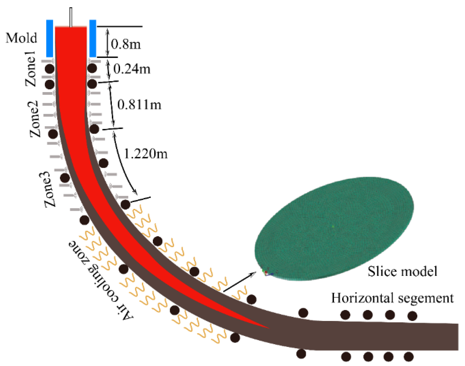
- In the model of F-EMS, the steel of the liquid core is seen as a circular platform body, while the length of the steel of the liquid core and the thickness of the billet solidified shell are calculated by ProCAST 2018 software;
- (5)
- Since the heat transfer in the cross-section direction of the continuous casting round billet is much greater than the heat transfer along the drawing direction, the heat transfer along the drawing direction of the casting round billet can be neglected;
- (6)
- In the continuous casting second cooling zone, the surface of the round billet cooled uniformly;
- (7)
- The effect of the steel flow on the internal heat transfer is not considered;
- (8)
- Ignoring the influence of the crystallizer vibration and other factors, the casting temperature is equal to the tundish temperature of the crystallizer;
- (9)
- The contact heat transfer and the surface radiation between the round billet and the support rolls are used for the integrated thermal conductivity.
2.2. Control Equations
2.2.1. Electromagnetic Field
2.2.2. Transfer Behavior
2.3. Boundary Conditions
2.3.1. Electromagnetic Field
- (1)
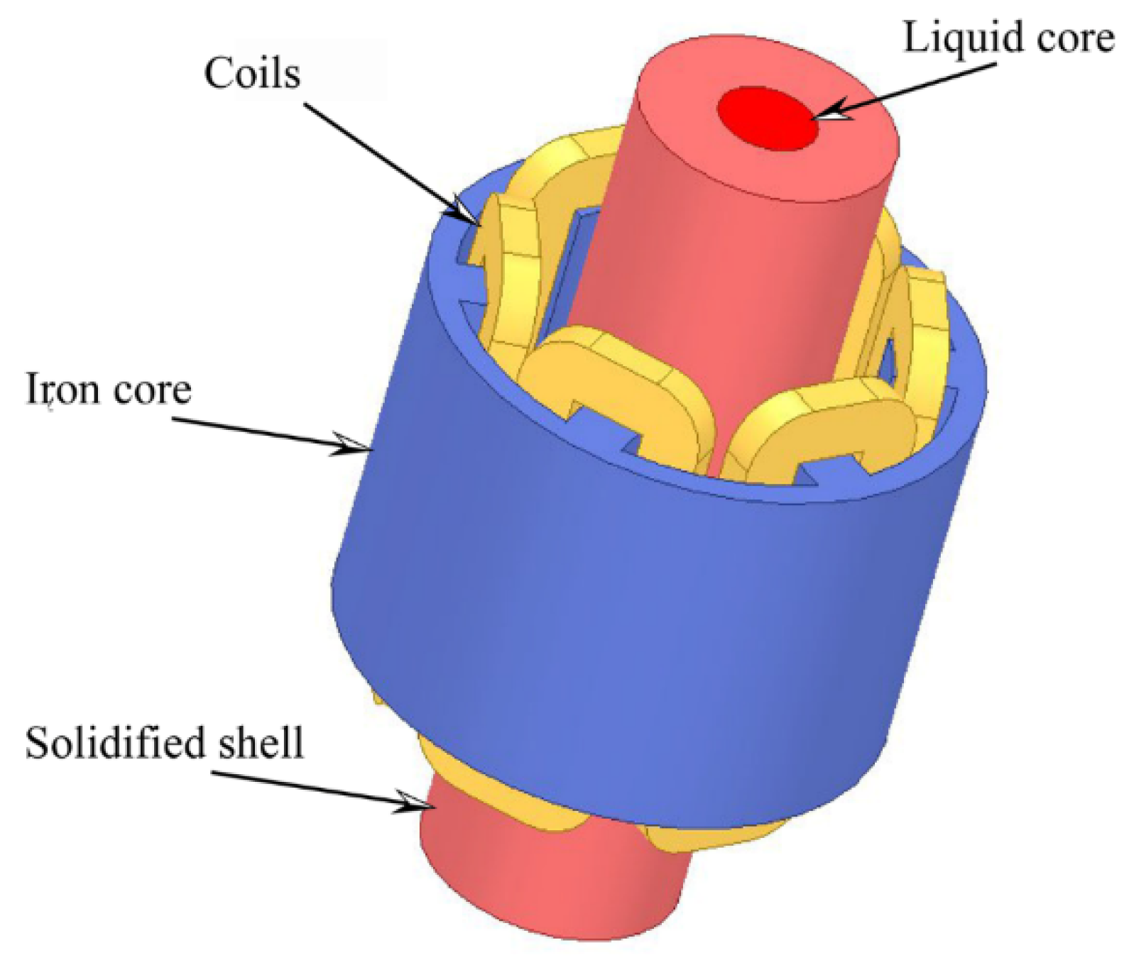
- The F-EMS uses three pairs of coil windings loaded with three-phase alternating current, with a phase difference of 120° for each phase.
- (2)
- The magnetic lines of force are parallel to the surface of the air unit enclosed outside the stirring.
- (3)
- The boundary condition between the coil and the core of the electromagnetic stirring is established as the insulation.
2.3.2. Flow and Solidification
- (1)
- The inlet temperature at the mold is equal to the casting temperature of the molten steel.
- (2)
- As the heat transfer coefficient of the 2D model varies with cooling zones, according to the above assumptions, the secondary cooling boundary conditions of each section are set as follows [21].
- (a)
- The moldwhere qm is the average heat flux at the surface of the casting billet in W·m−2; is the density of mold cooling water in kg·m−3; Q is the cooling water flow rate in m3·s−1; is the temperature difference between the inlet and outlet of the mold cooper in K; S is the effective contact area between the mold cooper and the casting billet in m2.
- (b)
- The secondary cooling zonewhere h1 and h2 are the heat transfer coefficient of the secondary cooling zone in W·m−2·K−1; is the water density in L·m−2·S−1; Tw is the temperature of the spray cooling flux in K; R is the water ratio of the continuous cooling water in L·kg−1; is the casting speed in m·min−1; S is the cross-sectional area of the billet in m2; is the density of the steel in kg·m−3; is the water distribution ratio of the second cooling zone in %; is the length of the nth zone in m.
- (c)
- The air-cooling zonewhere is the Stefan–Boltzmann constant, 5.67 × 10⁻⁸ W·(m2·K4)−1; is steel emissivity; Tw is the ambient temperature in K.
2.4. Solution Method
3. Geometric Model
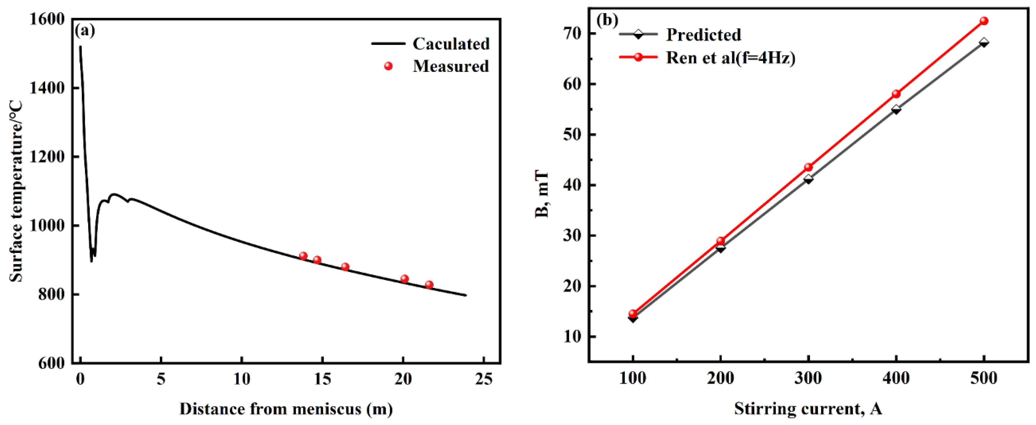
4. Model Validation
5. Results and Discussion
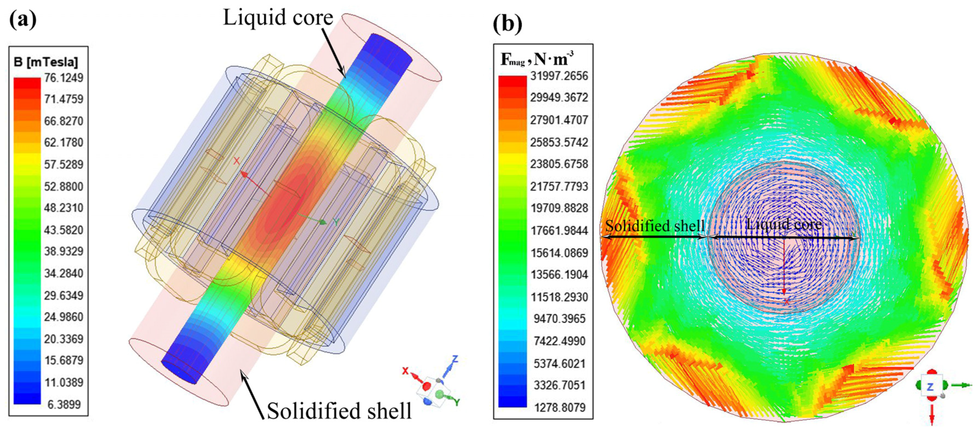
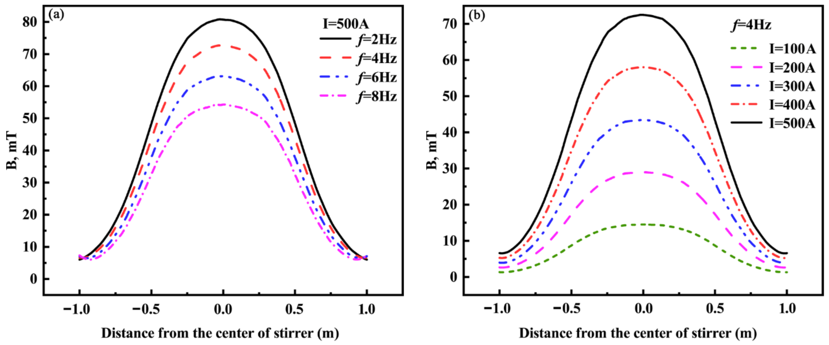
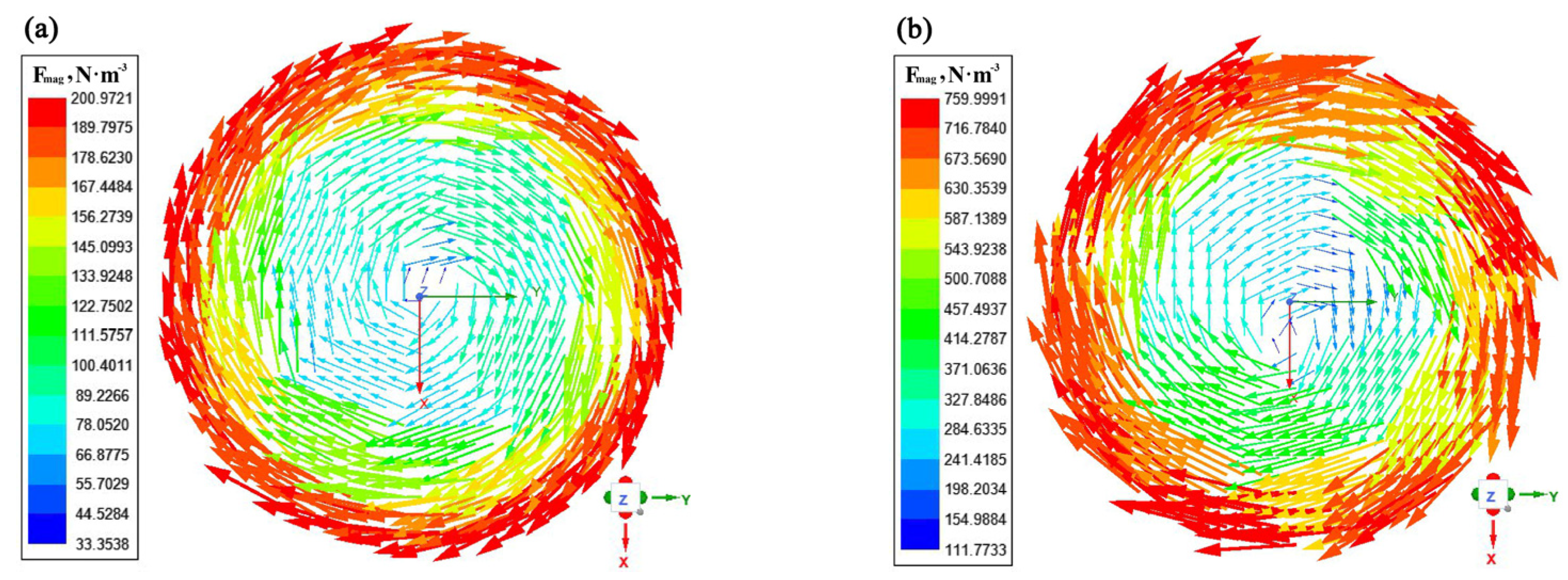
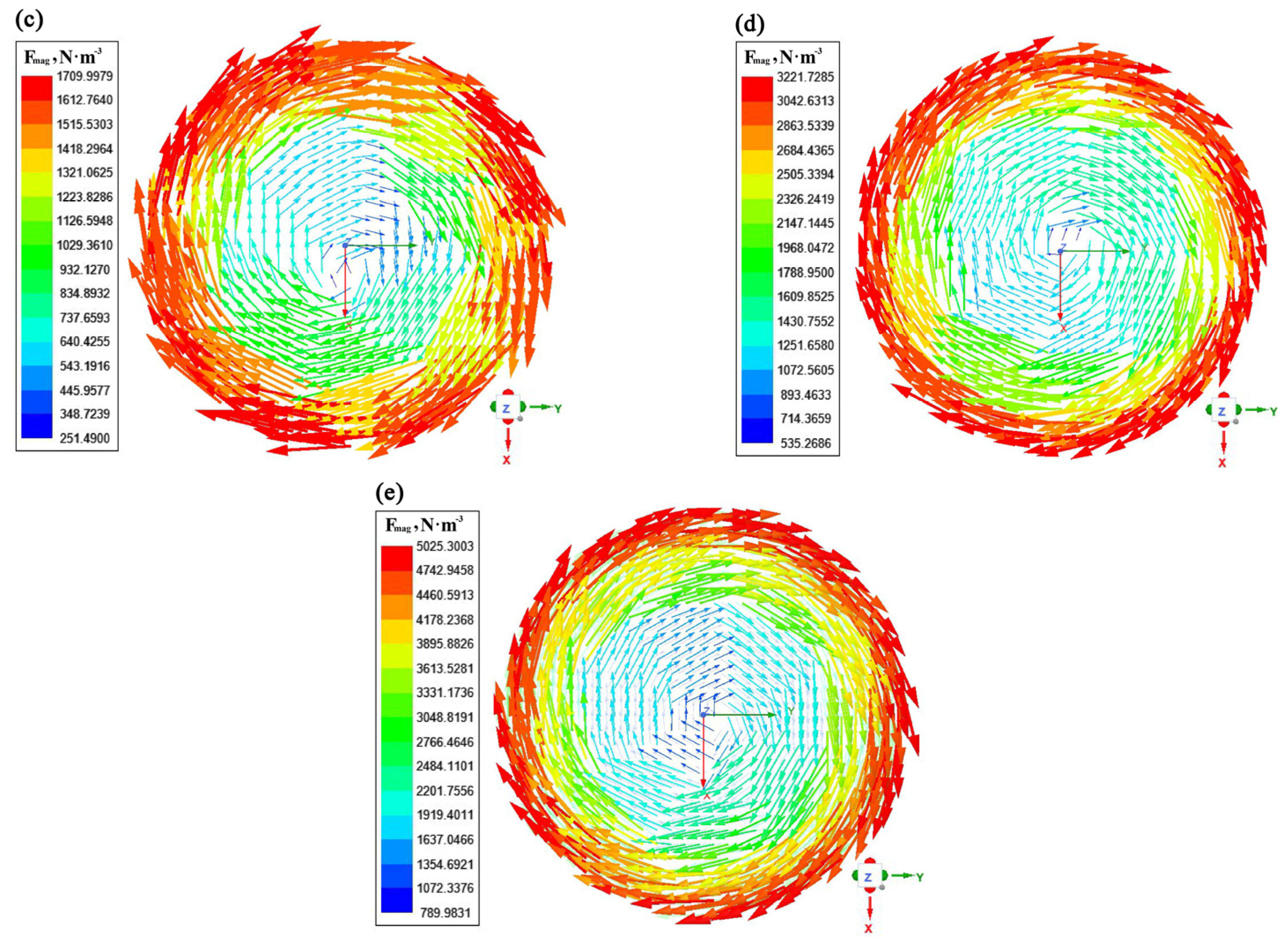
5.1. Effect of Current Frequency and Intensity on Electromagnetic Field for the Round Billet
5.2. Effect of Solidified Shell Conductivity on Electromagnetic Field for the Round Billets
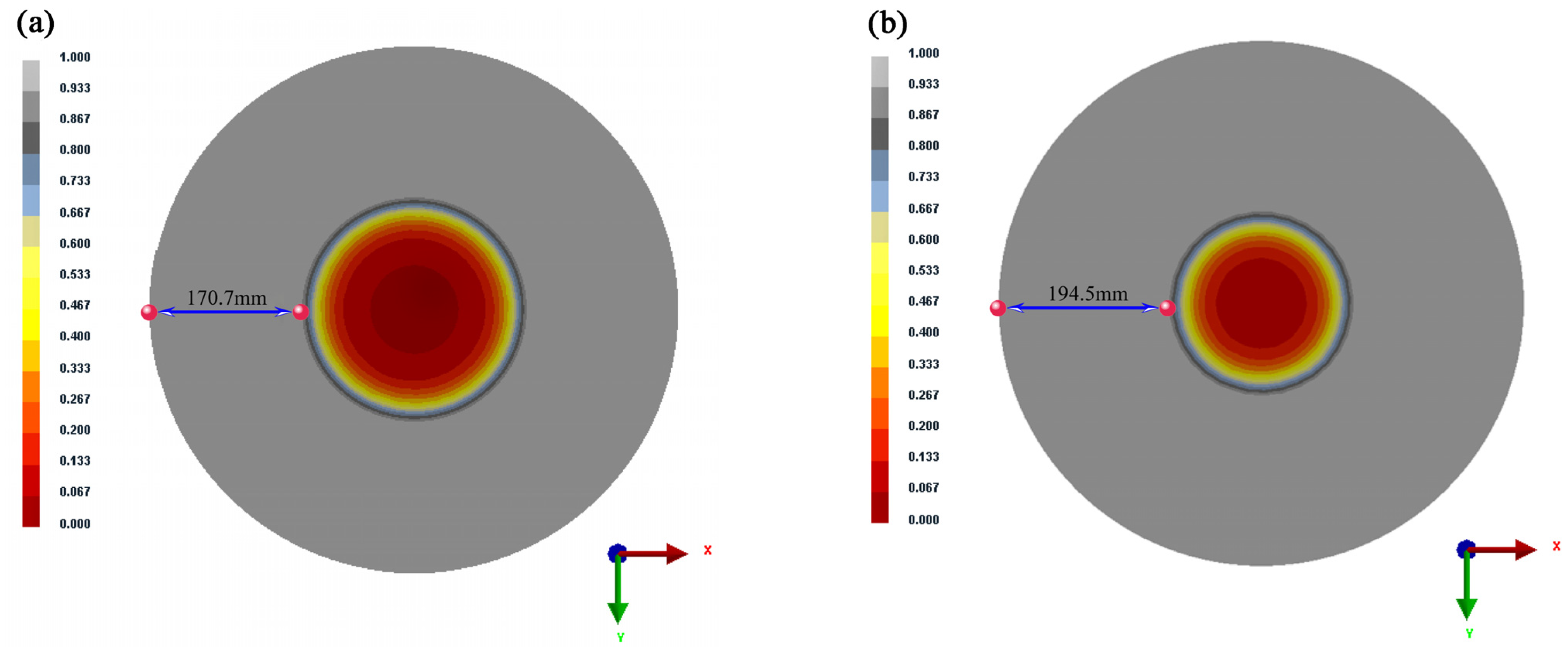
5.3. Effect of Round Billets Size on Electromagnetic Field
6. Conclusions
- (1)
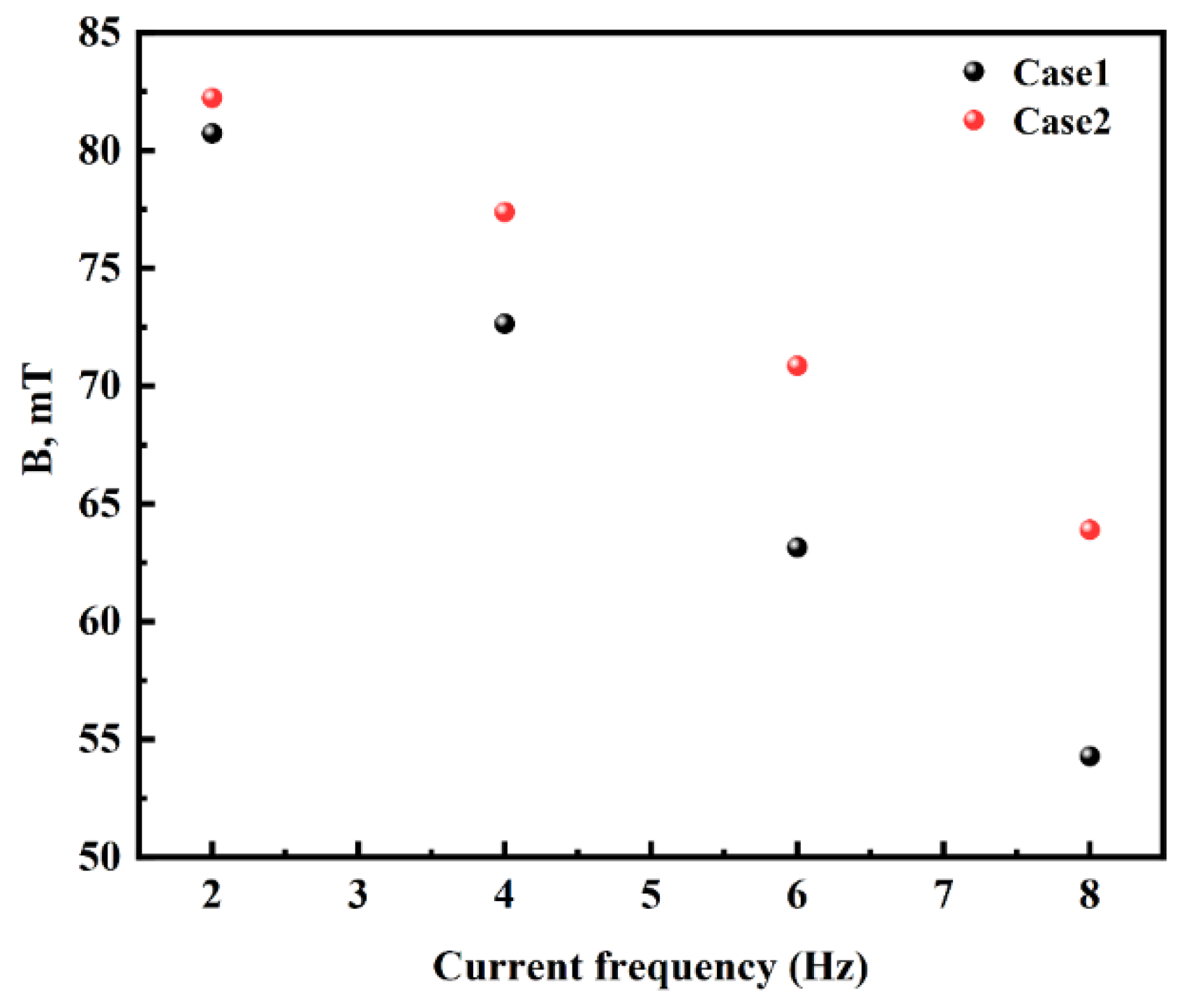
- With the increase in the frequency from 2 Hz to 8 Hz, the magnetic induction intensity on the central axis decreases, while the electromagnetic force on the transverse section of the liquid core initially increases and then decreases, reaching a maximum value of 5745.32 N·m−3 on the cross-section of the liquid core at the current frequency of 6 Hz. As the current frequency increases from 100 A to 500 A, the magnetic induction intensity and the electromagnetic force on the transverse of the liquid core increase.
- (2)
- With the rise of the solidified shell conductivity from 7.14 × 10⁵ S·m−1 to 1.0 × 10⁶ S·m−1, the magnetic induction intensity and electromagnetic force at the liquid core decrease at the same current frequency. As the current frequency increases, the difference between the stirrer center magnetic induction intensity and electromagnetic force increases for different solidified shell conductivities. The results of the simulation show that the optimal current frequency and current intensity of F-EMS are 6 Hz and 500 A for a Φ600 mm round bloom.
- (3)
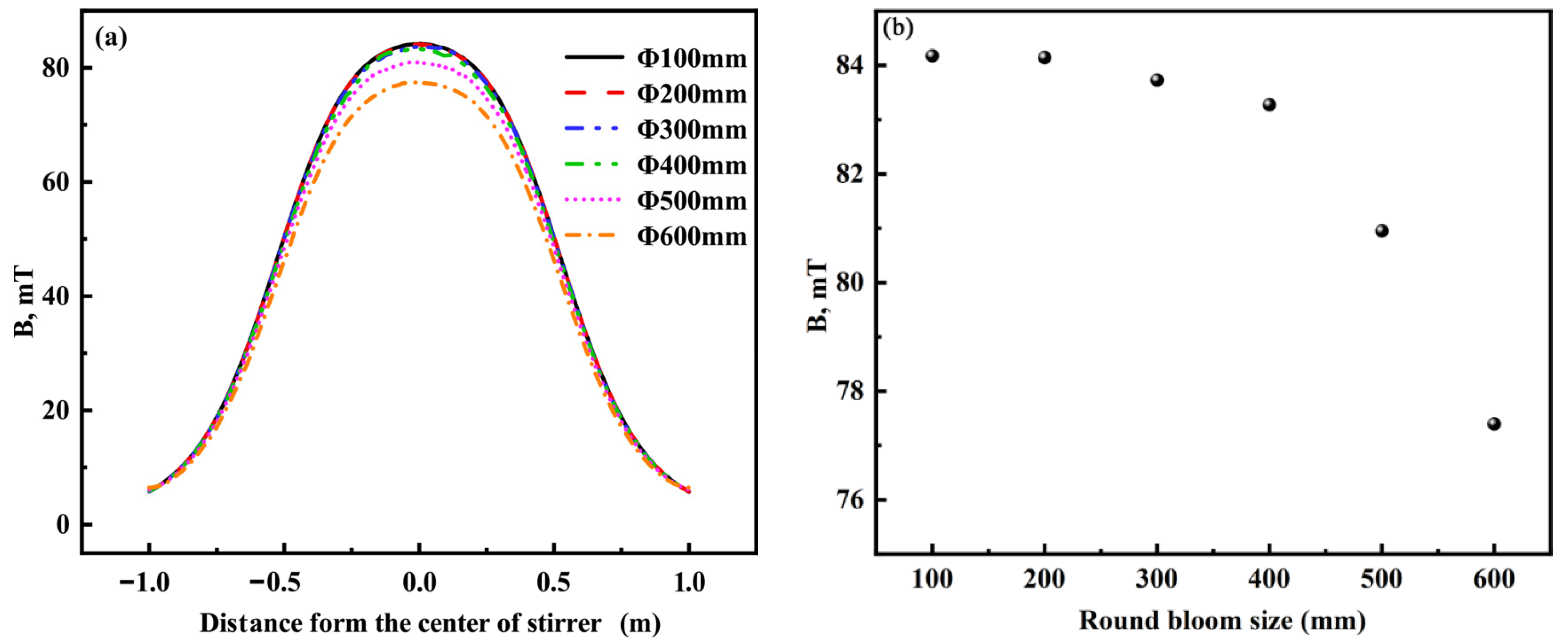
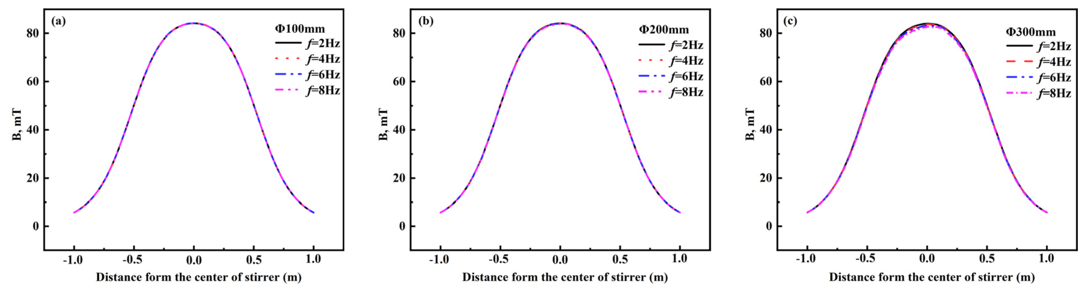
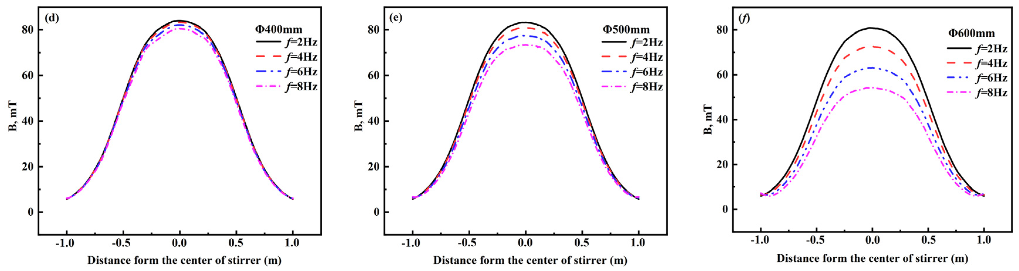
- The simulation results only consider the conditions of current frequency 2–8 Hz and round billets Φ100–Φ600 mm. In the range of round billets Φ100–Φ500 mm, the electromagnetic force increases with the rise of current frequency, while for billet Φ600 mm, the electromagnetic force increases and then decreases with the increase in current frequency. The magnetic induction intensity on the center axis of the stirrer rarely changes in the range of Φ100–Φ200 mm of the billets. When the current frequency is 2–8 Hz, the magnetic induction intensity on the center axis of the stirrer decreases slowly and then significantly as the round billet increases from Φ300 mm to Φ600 mm.
Author Contributions
Funding
Institutional Review Board Statement
Informed Consent Statement
Data Availability Statement
Conflicts of Interest
References
- Wu, H.J.; Xu, C.J.; Jin, H.Y.; Gao, Y.L.; Zhang, X.B.; Jin, Y.K. Effect of different positions of final electromagnetic stirring for ϕ800mm vertical round billet on fluid flow and heat transfer. Appl. Phys. A 2022, 128, 108. [Google Scholar] [CrossRef]
- Hu, W.; Ji, C.; Zhu, M. Numerical simulation of continuous casting round blooms with different solidification end reduction strategies. Mater. Trans. B 2021, 52, 4130–4140. [Google Scholar] [CrossRef]
- Javurek, M.; Barna, M.; Gittler, P.; Rockenschaub, K.; Lechner, M. Flow modelling in continuous casting of round bloom strands with electromagnetic stirring. Steel Res. Int. 2008, 79, 617–626. [Google Scholar] [CrossRef]
- Li, L.; Zhang, Z.; Luo, M.; Li, B.; Lan, P.; Zhang, J. Control of shrinkage porosity and spot segregation in Ø195 mm continuously cast round bloom of oil pipe steel by soft reduction. Metals 2020, 11, 9. [Google Scholar] [CrossRef]
- Sun, H.; Li, L. Formation and control of macrosegregation for round bloom continuous casting. Ironmak. Steelmak. 2015, 42, 683–688. [Google Scholar] [CrossRef]
- Wang, Y.; Zhang, L.; Chen, W.; Ren, Y. Three-dimensional macrosegregation model of bloom in curved continuous casting process. Mater. Trans. B 2021, 52, 2796–2805. [Google Scholar] [CrossRef]
- Jiang, D.; Zhang, L.; Wang, Y. Effect of mold electromagnetic stirring on solidification structure and solute segregation in continuous casting bloom. J. Iron Steel Res. Int. 2022, 29, 124–131. [Google Scholar] [CrossRef]
- Sun, H.; Li, L.; Cheng, X.; Qiu, W.; Liu, Z.; Zeng, L. Reduction in macrosegregation on 380 mm×490 mm bloom caster equipped combination M+F-EMS by optimising casting speed. Ironmak. Steelmak. 2014, 42, 439–449. [Google Scholar] [CrossRef]
- Ayata, K.; Mori, T.; Fujimoto, T.; Ohnishi, T.; Wakasugi, I. Improvement of macrosegregation in continuously cast bloom and billet by electromagnetic stirring. ISIJ Int. 1984, 24, 931–939. [Google Scholar] [CrossRef]
- Mizukami, H.; Komatsu, M.; Kitagawa, T.; Kawakami, K. Effect of electromagnetic stirring at the final stage of solidification of continuously cast strand. ISIJ Int. 1984, 24, 923–930. [Google Scholar] [CrossRef]
- Liu, H.; Chen, Y.; Qiu, H.; Wang, Z. Numerical simulation of coupled fluid flow and solidification in a curved round bloom continuous caster with a combined rotary electromagnetic stirring. Ironmak. Steelmak. 2022, 49, 506–521. [Google Scholar] [CrossRef]
- Li, X.; Wang, P.; Lan, P.; Liu, H.; Liu, Q.; Li, S.; Zhang, J. Melt flow and heat transfer at the crater end of round billet continuous casting using final electromagnetic stirring. Chin. J. Eng. 2019, 41, 748–756. [Google Scholar] [CrossRef]
- Fang, Q.; Zhang, H.; Wang, J.; Zhao, P.; Wu, G.; Ni, H. Effect of final electromagnetic stirring on flow, solidification, and solute transport in continuous casting bloom. JOM 2021, 73, 2698–2708. [Google Scholar] [CrossRef]
- Dong, Q.; Zhang, J.; Yin, Y.; Nagaumi, H. Numerical simulation of macrosegregation in billet continuous casting influenced by electromagnetic stirring. J. Iron Steel Res. Int. 2021, 29, 612–627. [Google Scholar] [CrossRef]
- Li, S.; Han, Z.; Zhang, J. Numerical modeling of the macrosegregation improvement in continuous casting blooms by using F-EMS. JOM 2020, 72, 4117–4126. [Google Scholar] [CrossRef]
- Ren, B.; Chen, D.; Xia, W.; Wang, H.; Han, Z. Numerical simulation of electromagnetic field in round bloom continuous casting with final electromagnetic stirring. Metals 2018, 8, 903. [Google Scholar] [CrossRef] [Green Version]
- Wan, Y.; Li, M.; Chen, L.; Wu, Y.; Li, J.; Pan, H.; Zhong, W. Effect of final electromagnetic stirring parameters on central cross-sectional carbon concentration distribution of high-carbon square billet. Metals 2019, 9, 665. [Google Scholar] [CrossRef] [Green Version]
- Li, S.; Lan, P.; Tang, H.; Tie, Z.; Zhang, J. Study on the electromagnetic field, fluid flow, and solidification in a bloom continuous casting mold by numerical simulation. Steel Res. Int. 2018, 89, 1800071. [Google Scholar] [CrossRef]
- Wang, P.; Tie, Z.; Li, S.; Lan, P.; Tang, H.; Zhang, J. Effect of M-EMS current intensity on the subsurface segregation and internal solidification structure for bloom casting of 42CrMo steel. Ironmak. Steelmak. 2021, 48, 779–787. [Google Scholar] [CrossRef]
- Yamazaki, M.; Natsume, Y.; Harada, H. Numerical simulation of solidification structure formation during continuous casting in Fe–0.7mass%C alloy using cellular automaton method. ISIJ Int. 2006, 46, 903–908. [Google Scholar] [CrossRef] [Green Version]
- Niu, L.; Qiu, S.T.; Zhao, J.X.; Chen, Y.Q.; Yang, S.F. Processing parameter optimization for continuous casting of 38CrMoAl round bloom based on a prediction model of the equiaxed crystal ratio. Ironmak. Steelmak. 2018, 46, 835–844. [Google Scholar] [CrossRef]
- Li, X.; Geng, X.; Zhan, D.; Zhouhua, J.; Peng, L.; Shi, S. Numerical simulation of electromagnetic field for round billet with final electromagnetic stirring. Contin. Cast. 2017, 41, 42–46. [Google Scholar] [CrossRef]
- Wu, H.; Xu, C.; Lei, C.; Wang, T.; Gao, Y.; Zhang, X.; Jin, H. Numerical simulation and industrial experiment of the fluid flow and heat transfer in large vertical round billets with helical final electromagnetic stirring. JOM 2023, 75, 1439–1449. [Google Scholar] [CrossRef]
- Beitelman, L. Effect of mold EMS design on billet casting productivity and product quality. Can. Metall. Q. 1999, 38, 301–309. [Google Scholar] [CrossRef]


| Parameters | Value |
|---|---|
| Round billet Diameter (mm) | 600 |
| Casting Speed (m·min−1) | 0.26 |
| Superheat (°C) | 30 |
| Current Frequency (Hz) | 2–8 |
| Current intensity (A) | 100–500 |
| Density of liquid steel (kg·m−3) | 7020 |
| Relative magnetic permeability of liquid core, solidified shell, air, and coil | 1.0 |
| Relative magnetic permeability of iron core | 1000 |
| Bulk conductivity of liquid core (S·m−1) | 7.14 × 10⁵ |
| Bulk conductivity of solidified shell [22] (S·m−1) | 1.0 × 10⁶ |
| Bulk conductivity of air (S·m−1) | 8.855 × 10⁻⁶ |
Disclaimer/Publisher’s Note: The statements, opinions and data contained in all publications are solely those of the individual author(s) and contributor(s) and not of MDPI and/or the editor(s). MDPI and/or the editor(s) disclaim responsibility for any injury to people or property resulting from any ideas, methods, instructions or products referred to in the content. |
© 2023 by the authors. Licensee MDPI, Basel, Switzerland. This article is an open access article distributed under the terms and conditions of the Creative Commons Attribution (CC BY) license (https://creativecommons.org/licenses/by/4.0/).
Share and Cite
Xu, G.; Tan, R.; Song, B.; Liu, W.; Yang, S.; Zuo, X.; Huang, Y. Numerical Simulation of the Effect of Solidified Shell Conductivity and Billet Sizes on the Magnetic Field with Final Electromagnetic Stirring in Continuous Casting. Materials 2023, 16, 4765. https://doi.org/10.3390/ma16134765
Xu G, Tan R, Song B, Liu W, Yang S, Zuo X, Huang Y. Numerical Simulation of the Effect of Solidified Shell Conductivity and Billet Sizes on the Magnetic Field with Final Electromagnetic Stirring in Continuous Casting. Materials. 2023; 16(13):4765. https://doi.org/10.3390/ma16134765
Chicago/Turabian StyleXu, Guofang, Ruisong Tan, Bo Song, Wei Liu, Shufeng Yang, Xiaotan Zuo, and Yan Huang. 2023. "Numerical Simulation of the Effect of Solidified Shell Conductivity and Billet Sizes on the Magnetic Field with Final Electromagnetic Stirring in Continuous Casting" Materials 16, no. 13: 4765. https://doi.org/10.3390/ma16134765