
Shape Memory Alloys Applied to Automotive Adaptive Aerodynamics
 , , and
Abstract
:1. Introduction
2. Theoretical Background
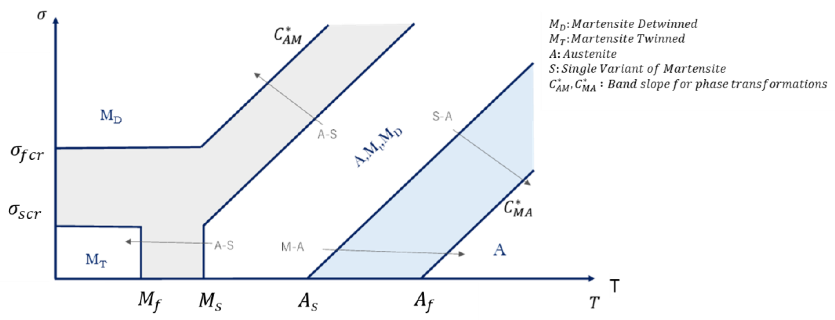
2.1. Thermomechanical Law
2.2. Kinetic Law
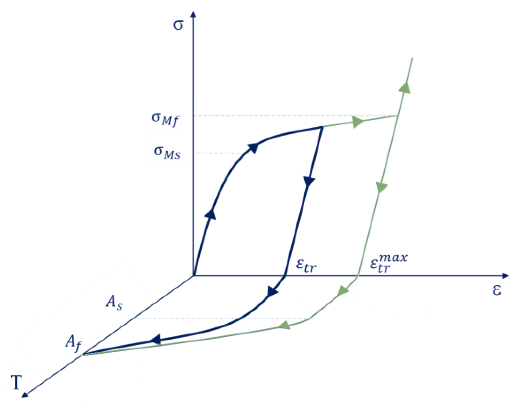
2.3. Austenite–Martensite Phase Transformation
2.4. Martensite–Austenite Phase Transformation
3. User Material Subroutine (SMA Constitutive Relations)
4. Bistable SMA Actuator for a Skid Plate
4.1. Aerodynamic and Operative Requirements
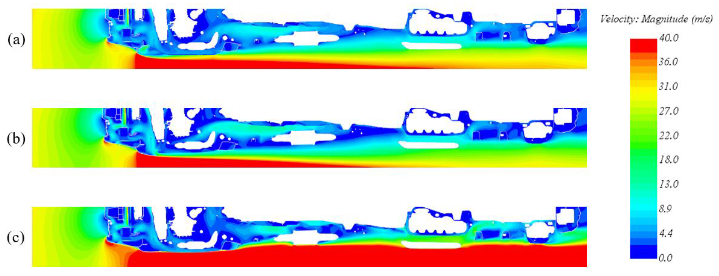
- The aerodynamic behavior of the deactivated configuration is comparable with the base model. The front air dam removal and the new geometry of the skid plate have no significant impact either on the total Cx value of the car or on the velocity field, which is very similar to the base model one.
- The aerodynamic behavior of the activated configuration shows the necessity and the purpose of this activity. It is not possible to simply consider the removal of the front air dam, as this would have a significant impact on the vehicle total Cx with an increase of about 7%, justified by the velocity field shown in Figure 6 (without the effect of the front air dam, the flow impacts directly on all the components in the underhood, significantly increasing the pressure on the underbody mechanical components).
4.2. Skid Plate Geometrical, Material, and Boundary Conditions Description
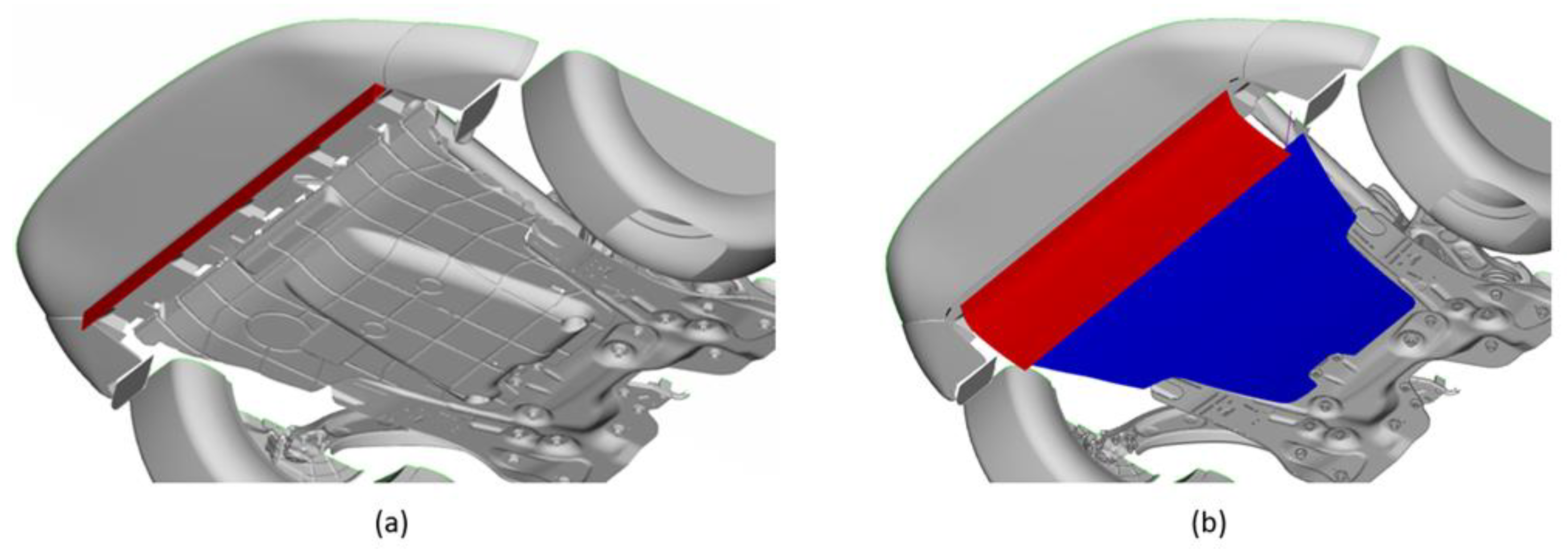
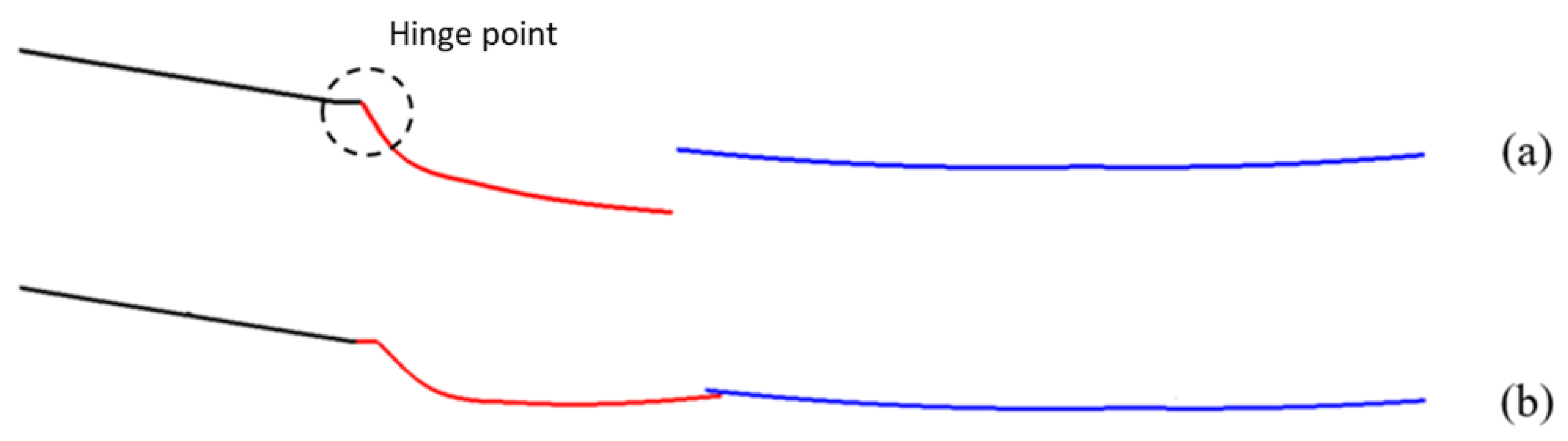
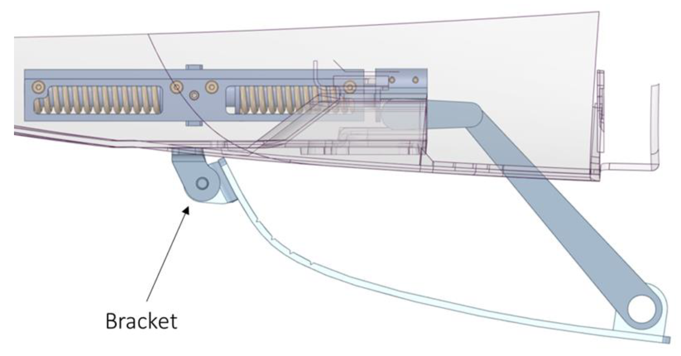
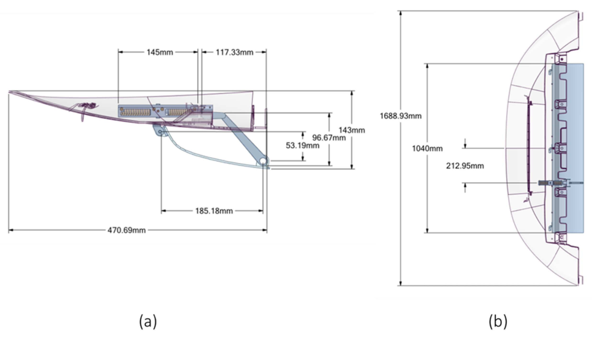
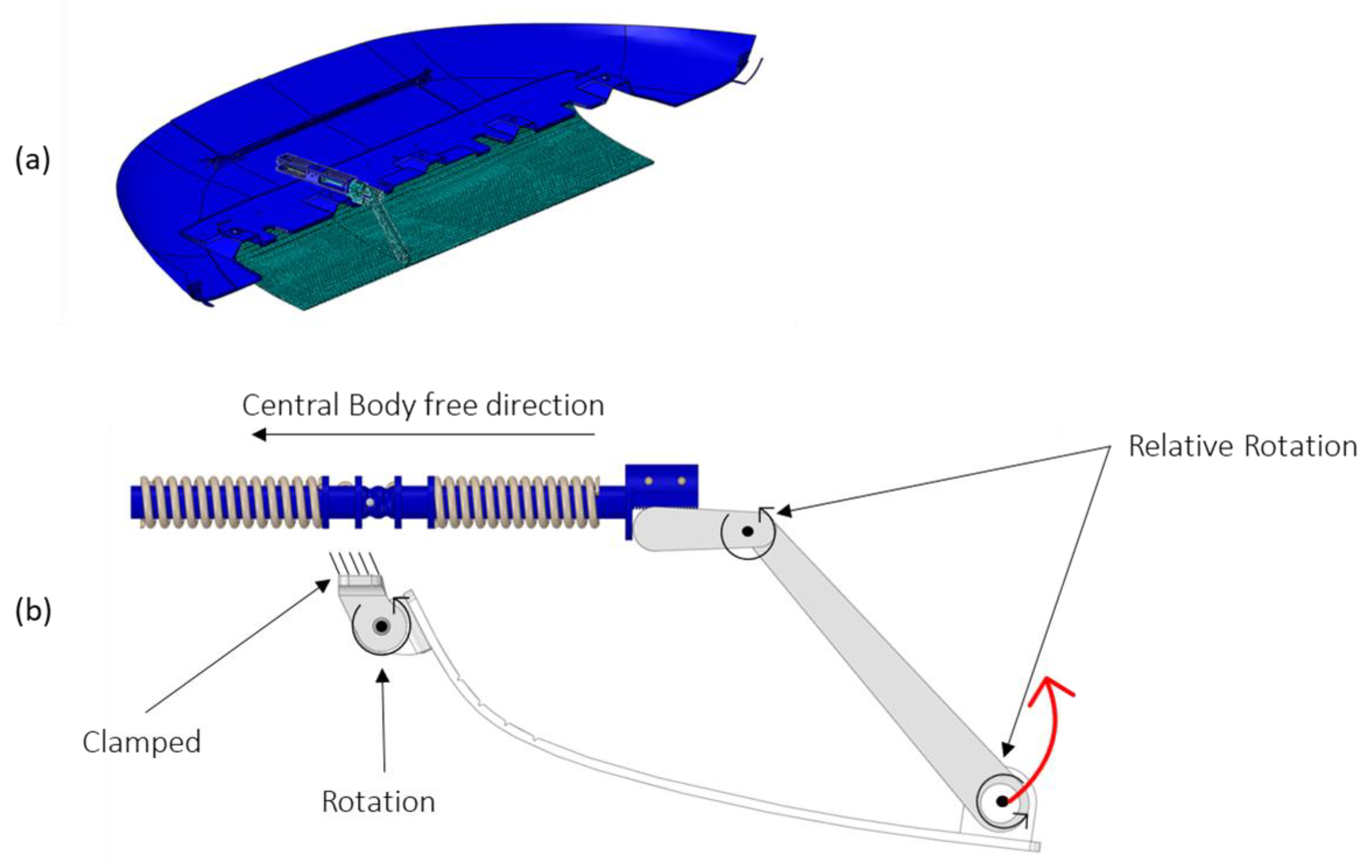
4.2.1. Skid Plate
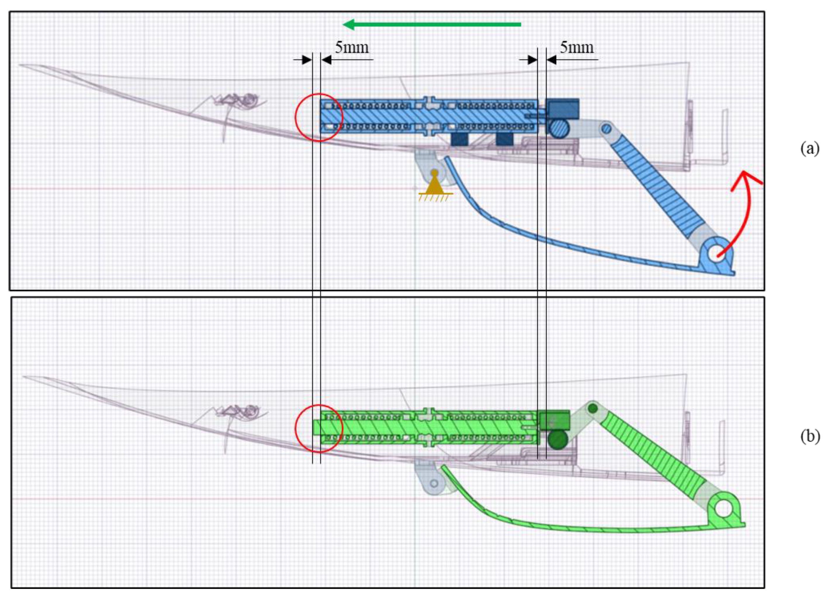
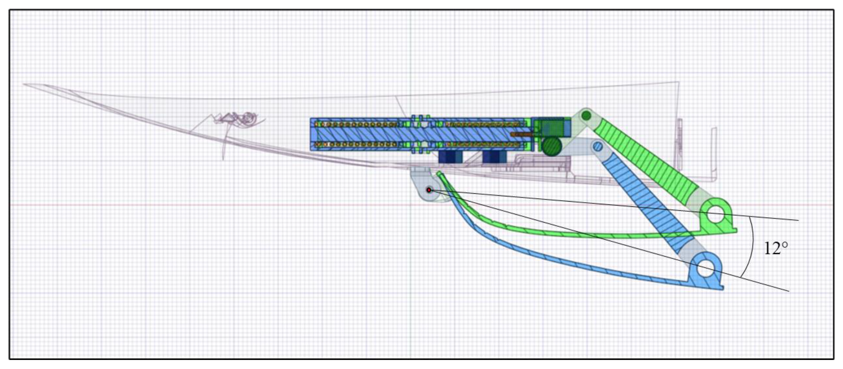
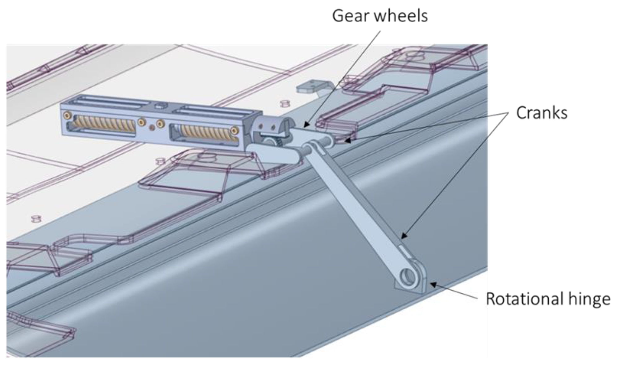
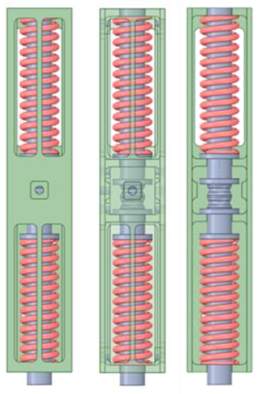
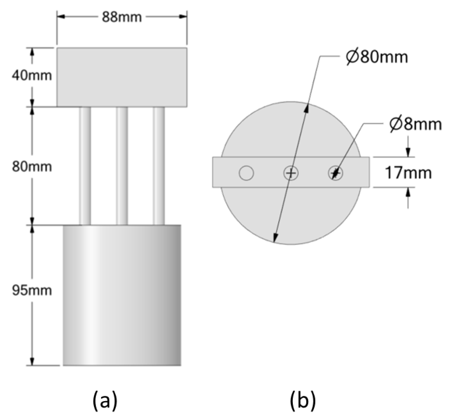
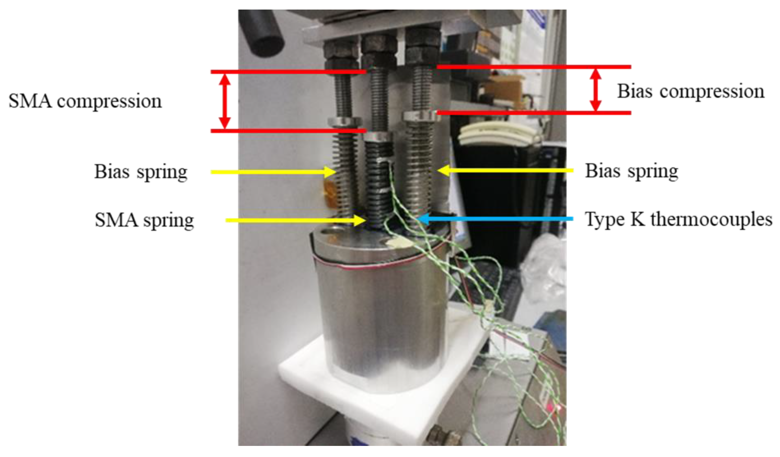
4.2.2. Bistable SMA Actuator
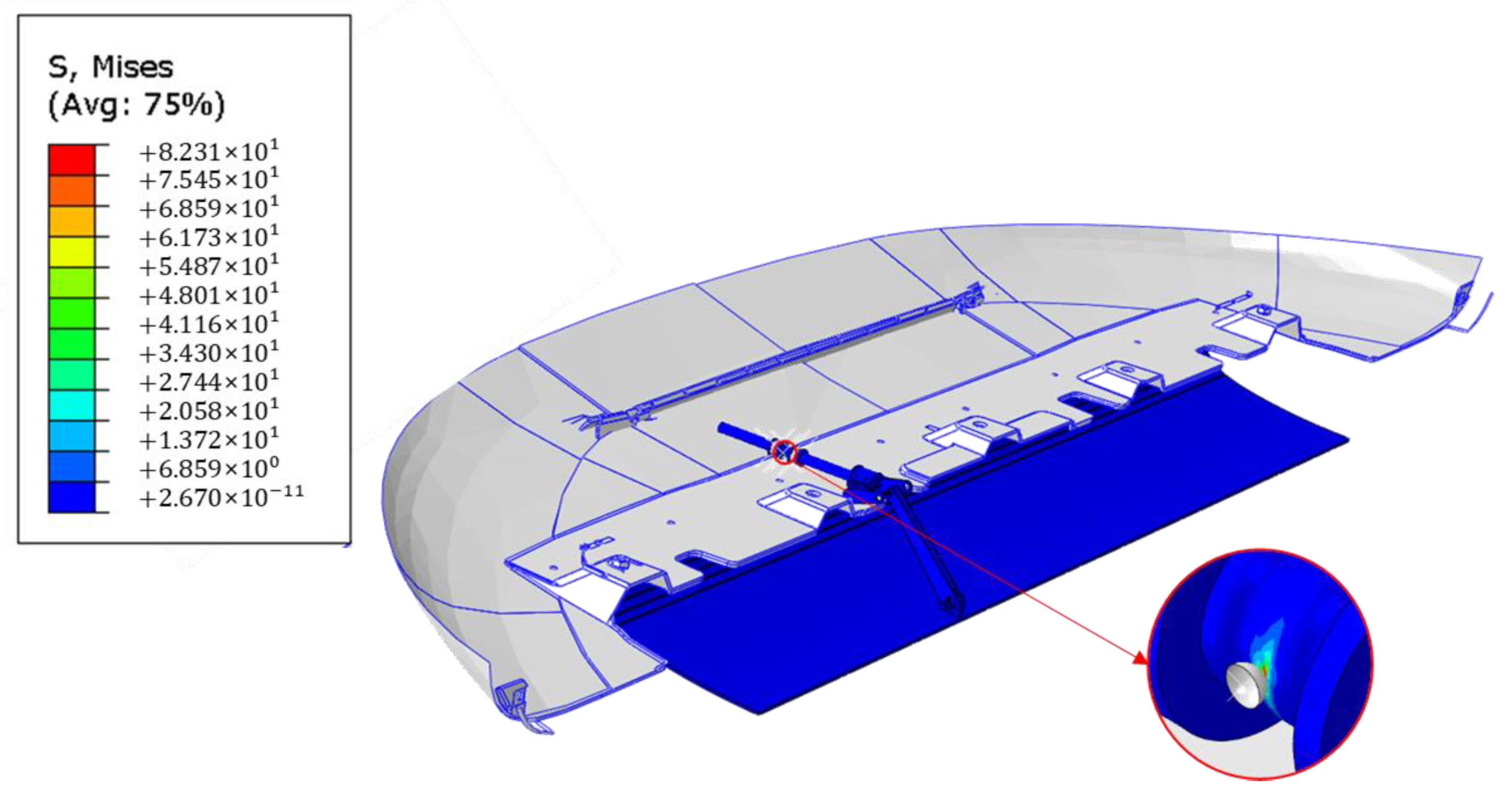
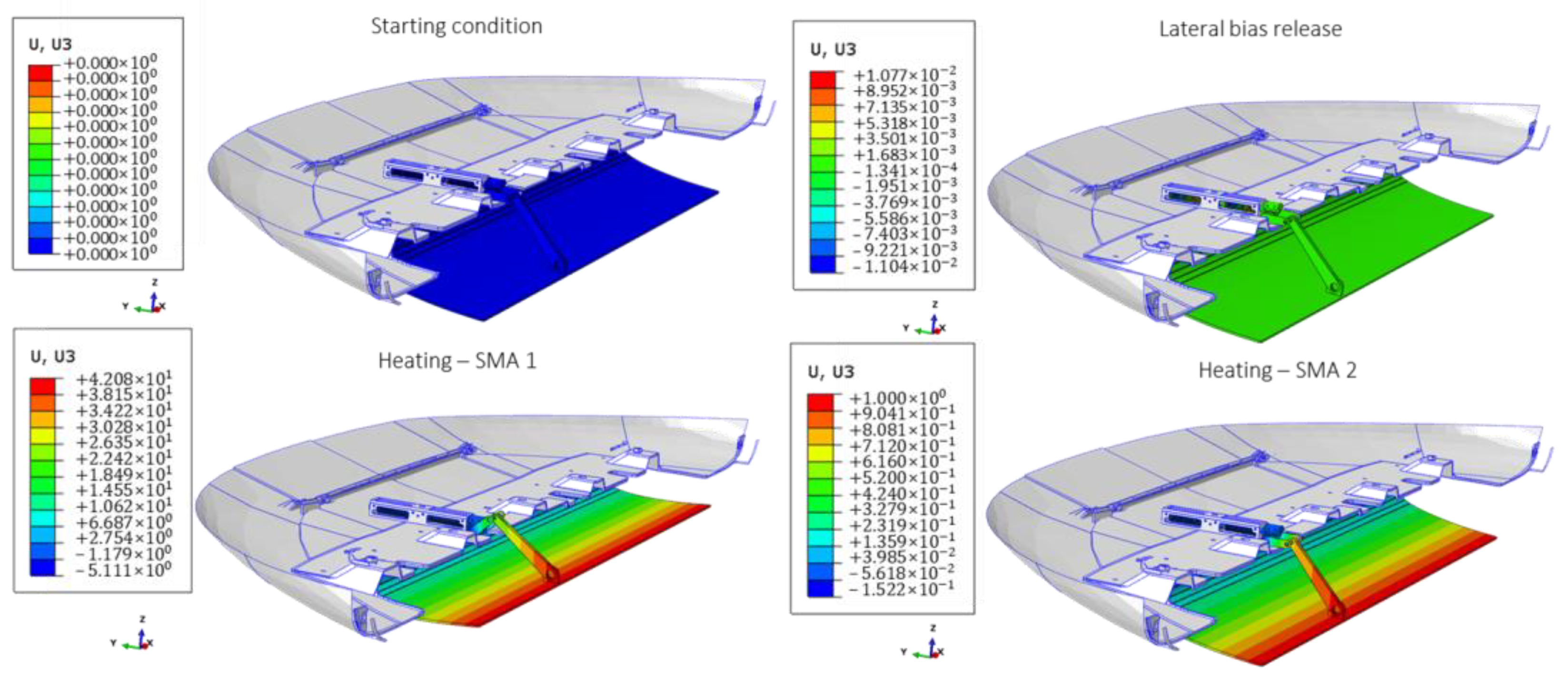
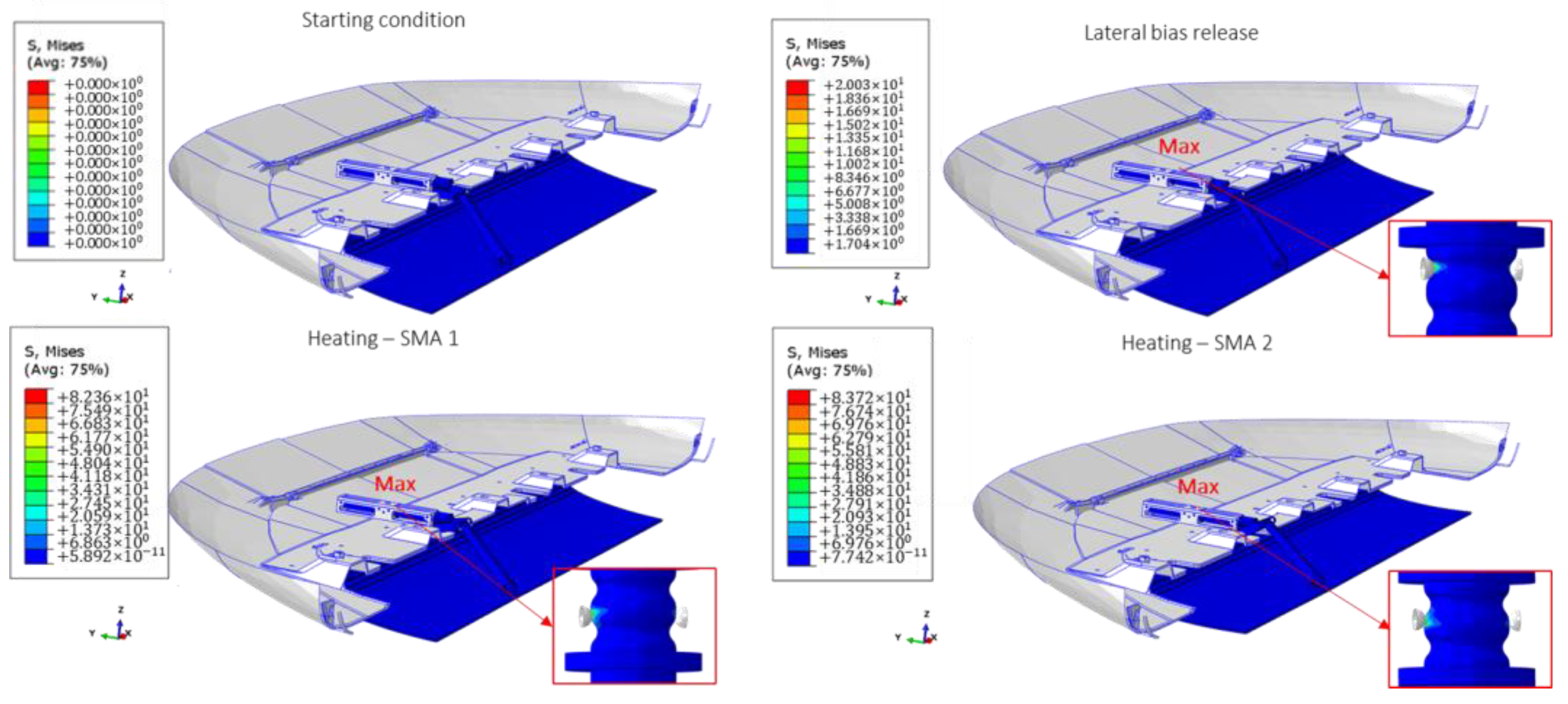
4.3. Results and Discussion
5. Conclusions
- Based on the aerodynamic study, rotating the plate by 12° in two stable configurations led to a significant improvement in its durability, but did not significantly enhance its aerodynamic performance.
- A preliminary analysis to verify the kinematic motion revealed that a force of approximately 35 N is required to move the skid plate system.
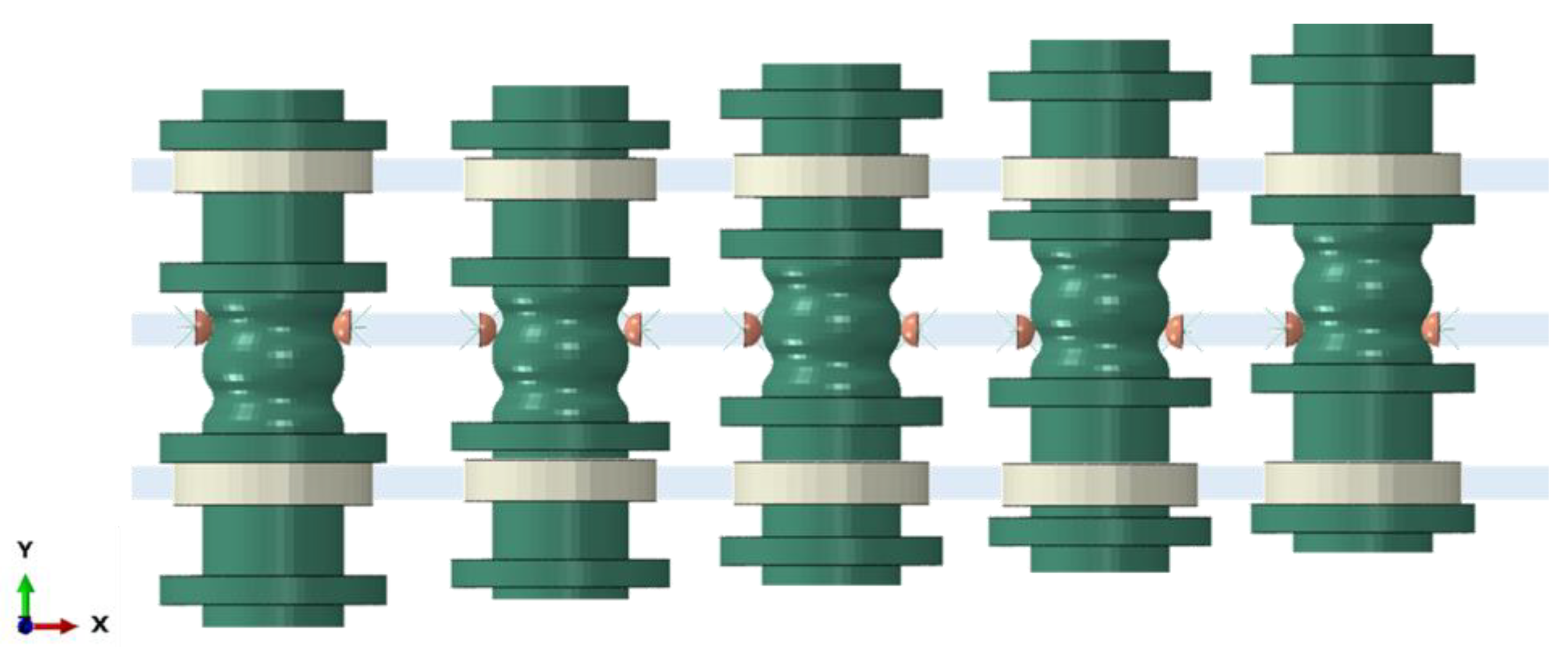
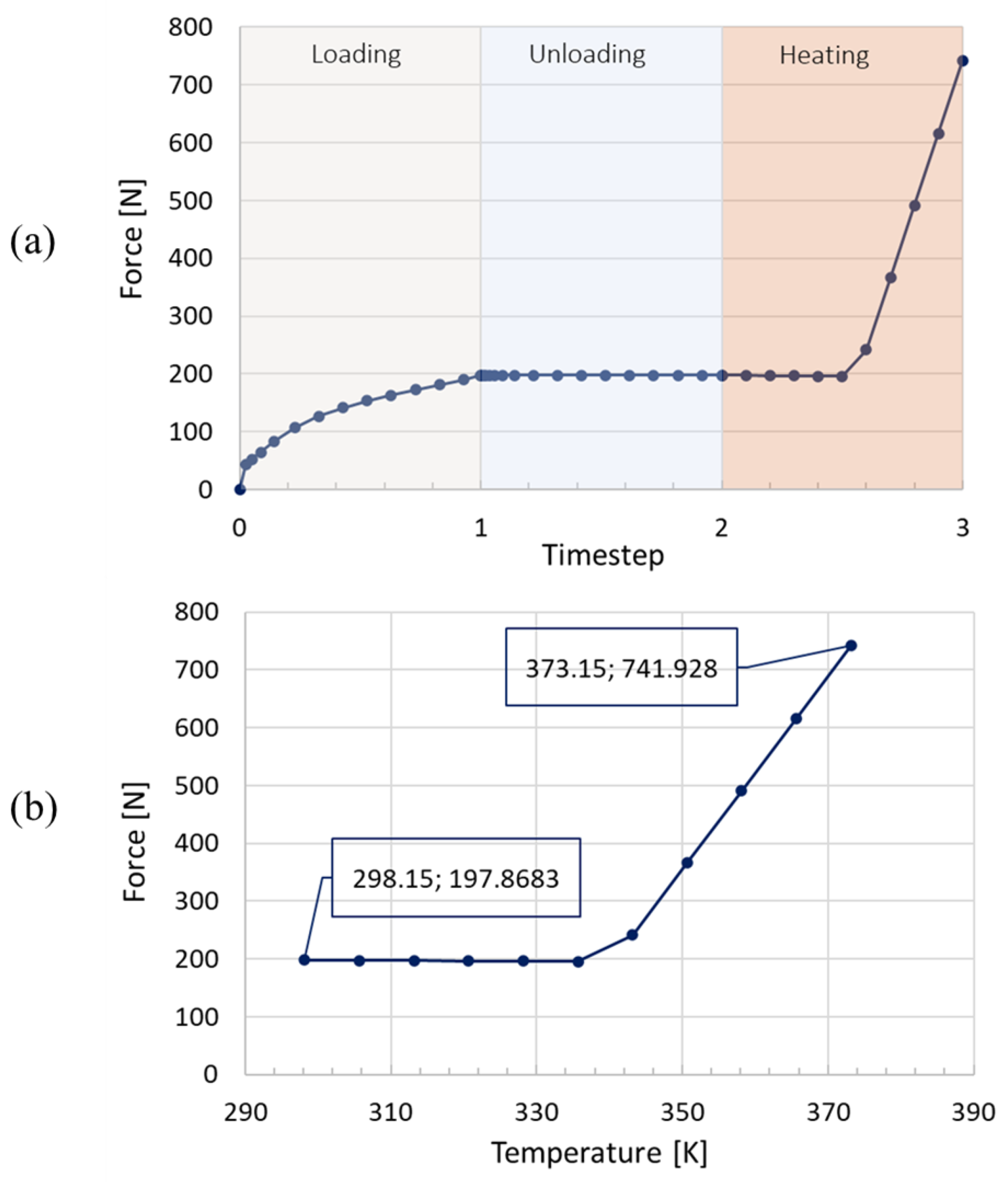
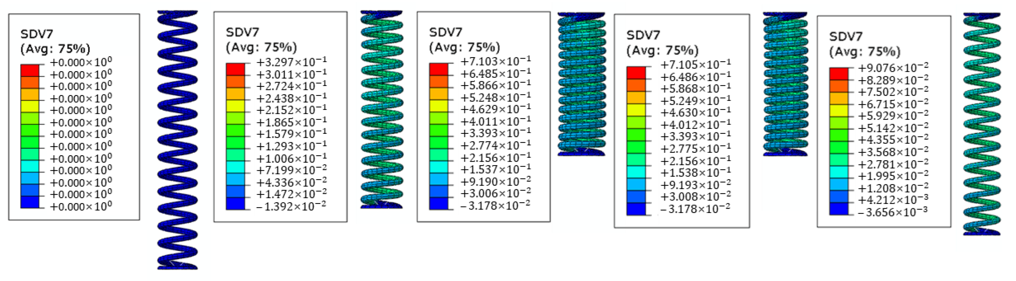
- Using the UMAT in Abaqus software, the thermomechanical properties of both shape memory alloy effects were simulated. The numerical analysis results indicate that the SMA spring system produces a maximum force that is 21% greater than the required force.
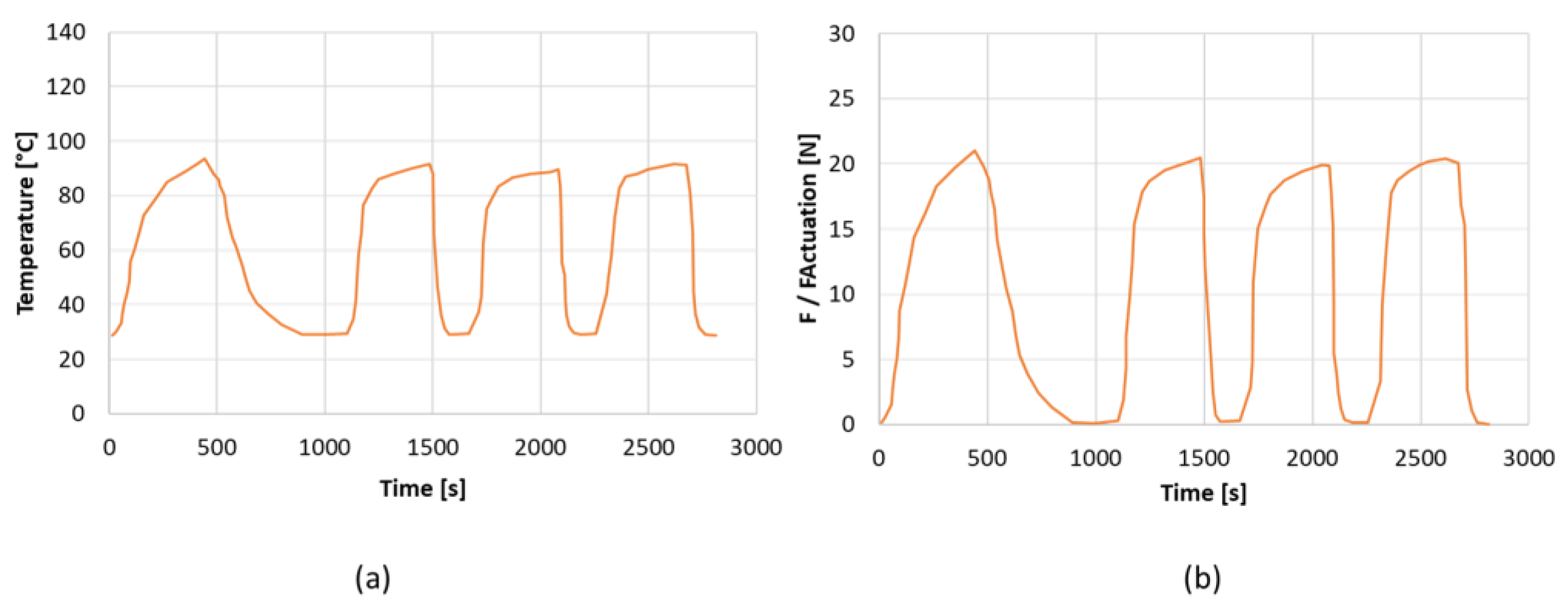
- To verify the force generated by the SMA spring, three experimental tests were performed. Although all tested configurations met the force requirement, the first configuration, which has the smallest footprint, was selected.
- A final analysis of the entire system demonstrated the feasibility of the proposed actuator and the stability of the two possible configurations of the SMA skid plate system.
Author Contributions
Funding
Institutional Review Board Statement
Informed Consent Statement
Data Availability Statement
Acknowledgments
Conflicts of Interest
References
- Gandhi, M.V.; Thompson, B.S. Smart Materials and Structures; Chapman & Hall: New York, NY, USA, 1992. [Google Scholar]
- Huang, W.M.; Ding, Z.; Wang, C.C.; Wei, J.; Zhao, Y.; Purnawali, H. Shape memory materials. Mater. Today 2010, 13, 54–61. [Google Scholar] [CrossRef]
- Duerig, T.W.; Melton, K.N.; Stökel, D.; Wayman, C.M. (Eds.) Engineering Aspects of Shape Memory Alloys; Butterworth-Heinemann: London, UK, 1990. [Google Scholar]
- Pelton, A.R.; Hodgson, D.; Duerig, T. (Eds.) SMST-94. Proceedings of the First International Conference on Shape Memory and Superelastic Technologies, Asilomar, CA, USA, 7–10 March 1994; MIAS: Monterey, CA, USA, 1995. [Google Scholar]
- Pelton, A.R.; Hodgson, D.; Duerig, T. (Eds.) SMST-97. Proceedings of Second International Conference on Shape Memory and Superelastic Technologies, Asilomar, CA, USA, 2–6 March 1997; SMST: Santa Clara, CA, USA, 1997. [Google Scholar]
- Barras, C.D.J.; Myers, K.A. Nitinol—Its Use in Vascular Surgery and Other Applications. Eur. J. Vasc. Endovasc Surg. 2000, 19, 564–569. [Google Scholar] [CrossRef] [PubMed] [Green Version]
- Wu, M.H.; Schetky, L.M. Industrial applications for shape memory alloys. (Vol. 171). In SMST-2000. Proceedings of the International Conference on Shape Memory and Superelastic Technologies, Pacific Grove, CA, USA, 30 April–4 May 2000; SMST: Pacific Grove, CA, USA, 2000. [Google Scholar]
- Wei, Z.; Sandstroröm, R.; Miyazaki, S. Shape-memory materials and hybrid composites for smart systems: Part I Shape-memory materials. J. Mater. Sci. 1998, 33, 3743–3762. [Google Scholar] [CrossRef]
- El Feninat, F.; Laroche, G.; Fiset, M.; Mantovani, D. Shape memory materials for biomedical applications. Adv. Eng. Mater. 2002, 4, 91. [Google Scholar] [CrossRef]
- Hornbogen, E. Comparison of shape memory metals and polymers. Adv. Eng. Mater. 2006, 8, 101–106. [Google Scholar] [CrossRef]
- Gunes, I.S.; Jana, S.C. Shape memory polymers and their nanocomposites: A review of science and technology of new multifunctional materials. J. Nanosci. Nanotechnol. 2008, 8, 1616–1637. [Google Scholar] [CrossRef]
- Khachaturyan, A. Theory of Structural Transformations in Solid; John Wiley & Sons: Hoboken, NJ, USA, 1983. [Google Scholar]
- Wayman, C. Introduction of elastic plastic flow. In Methods in Computational Physics; Academic Press: Cambridge, MA, USA, 1964; Volume 3, pp. 211–263. [Google Scholar]
- Duerig, T.W.; Bhattacharya, K. The influence of the R-phase on the superelastic behavior of NiTi. Shape Mem. Superelasticity 2015, 1, 153–161. [Google Scholar] [CrossRef]
- Assawakawintip, T.; Santiwong, P.; Khantachawana, A.; Sipiyaruk, K.; Chintavalakorn, R. The Effects of Temperature and Time of Heat Treatment on Thermo-Mechanical Properties of Custom-Made NiTi Orthodontic Closed Coil Springs. Materials 2022, 15, 3121. [Google Scholar] [CrossRef]
- Lee, J.; Shin, Y.C. Effects of composition and post heat treatment on shape memory characteristics and mechanical properties for laser direct deposited nitinol. Lasers Manuf. Mater. Process. 2019, 6, 41–58. [Google Scholar] [CrossRef]
- Tsaturyants, M.; Sheremetyev, V.; Dubinskiy, S.; Komarov, V.; Polyakova, K.; Korotitskiy, A.; Prokoshkin, S.; Borisov, E.; Starikov, K.; Kaledina, D.; et al. Structure and Properties of Ti–50.2 Ni Alloy Processed by Laser Powder Bed Fusion and Subjected to a Combination of Thermal Cycling and Heat Treatments. Shape Mem. Superelasticity 2022, 8, 16–32. [Google Scholar] [CrossRef]
- Ryklina, E.P.; Polyakova, K.A.; Resnina, N.N. Role of Structural Heredity in Aging-Induced Microstructure and Transformation Behavior in Ni-rich Titanium Nickelide. Shape Mem. Superelasticity 2022, 8, 200–214. [Google Scholar] [CrossRef]
- Ren, J.R.; Shuitcev, A.V.; Bin, S.; Feng, C.; Li, L.; Tong, Y.X. Evolution of Ti3Ni4 precipitates in Ti49.2Ni50.8 alloy during equal channel angular pressing. Trans. Nonferrous Met. Soc. China 2021, 31, 980–987. [Google Scholar] [CrossRef]
- Brinson, L.C.; Huang, M.S. Simplifications and comparisons of shape memory alloy constitutive models. J. Intell. Mater. Syst. Struct. 1996, 7, 108–114. [Google Scholar] [CrossRef]
- Brocca, M.; Brinson, L.C.; Bazant, Z.P. Three dimensional constitutive model for shape memory alloys based on microplane model. J. Mech. Phys. Solids 2002, 50, 1051–1077. [Google Scholar] [CrossRef]
- Auricchio, F.; Taylor, R.L.; Lubliner, J. Shape memory alloys: Macromodelling and numerical simulations of the superelastic behavior. Comput. Methods Appl. Mech. Eng. 1997, 146, 281–312. [Google Scholar] [CrossRef]
- Auricchio, F. A robust integration algorithm for a finite strain shape memory alloy superelastic model. Int. J. Plast. 2001, 17, 971–990. [Google Scholar] [CrossRef]
- Liang, C.; Rogers, C.A. A multi-dimensional constitutive model for shape memory alloys. J. Eng. Math. 1992, 26, 429–443. [Google Scholar] [CrossRef]
- Boyd, J.G.; Lagoudas, D.C. A thermodynamical constitutive model for shape memory materials: Part 1: The monolithic shape memory alloy. Int. J. Plast. 1996, 12, 805–842. [Google Scholar] [CrossRef]
- Boyd, J.G.; Lagoudas, D.C. A thermodynamical constitutive model for shape memory materials: Part 2: The SMA composite material. Int. J. Plast. 1996, 12, 843–873. [Google Scholar] [CrossRef]
- Lagoudas, D.C.; Bo, Z.; Qidwai, M.A. A unified thermodynamic constitutive model for SMA and finite element analysis of active metal matrix composites. Mech. Compos. Mater. Struct. 1996, 4, 153–179. [Google Scholar] [CrossRef]
- Sun, Q.P.; Hwang, K.C. Micromechanics modelling for the constitutive behavior of polycrystalline shape memory alloys (part 1 and 2). J. Mech. Phys. Solids 1993, 41, 1–33. [Google Scholar] [CrossRef]
- Gao, X.; Huang, M.; Brinson, L.C. A multivariant micromechanical model for SMAs: Part 1: Crystallographic issues for single crystal model. Int. J. Plast. 2000, 16, 1345–1369. [Google Scholar] [CrossRef]
- Huang, M.S.; Gao, X.; Brinson, L.C. A multivariant micromechanical model for SMAs: Part 2: Polycrystal model. Int. J. Plast. 2000, 16, 1371–1399. [Google Scholar] [CrossRef]
- Brinson, L.C.; Lammering, R. Finite element analysis of the behaviour of shape memory alloys and their applications. Int. J. Solids Struct. 1993, 30, 3261–3280. [Google Scholar] [CrossRef]
- Franois, T.; Yuan, Y.Q. Nonlinear finite element simulation of superelastic shape memory alloy parts. Comput. Struct. 1997, 67, 799–810. [Google Scholar]
- Ghomshei, M.M.; Tabandeh, N.; Khajepour, A.; Behdinan, K. Finite Element Analysis of a New Shape Memory Alloy Composite Actuator. In Proceedings of the 8th Annual Conference of the CFD Society of Canada, Montreal, QC, Canada, 11–13 June 2000; Volume 2, pp. 755–762. [Google Scholar]
- Kang, W.-R.; Kim, E.-H.; Jeong, M.-S.; Lee, I.; Ahn, S.-M. Morphing wing mechanism using an SMA wire actuator. Int. J. Aeronaut. Space Sci. 2012, 13, 58–63. [Google Scholar] [CrossRef] [Green Version]
- Mizzi, L.; Spaggiari, A.; Dragoni, E. Design-oriented modelling of composite actuators with embedded shape memory alloy. Compos. Struct. 2019, 213, 37–46. [Google Scholar] [CrossRef]
- Varughese, K.; El-Hacha, R. Design and behaviour of steel braced frame reinforced with NiTi SMA wires. Eng. Struct. 2020, 212, 110502. [Google Scholar] [CrossRef]
- Lee, H.J.; Lee, J.J.; Huh, J.S. A simulation study on the thermal buckling behavior of laminated composite shells with embedded shape memory alloy (SMA) wires. Compos. Struct. 1999, 47, 463–469. [Google Scholar] [CrossRef]
- Chen, T.; Jiang, J.; Zhang, Q.; Wang, H.; Zhang, X. Experiments and modeling of variable camber guide vane embedded with shape memory alloy plate. Smart Mater. Struct. 2021, 30, 045012. [Google Scholar] [CrossRef]
- Ghaznavi, A.; Shariyat, M. Effects of asymmetric behavior of shape memory alloy on nonlinear dynamic responses of thick sandwich plates with embedded SMA wires. J. Comput. Appl. Res. Mech. Eng. 2020, 9, 183–197. [Google Scholar]
- Strelec, J.K.; Lagoudas, D.C.; Khan, M.A.; Yen, J. Design and implementation of a shape memory alloy actuated reconfigurable airfoil. J. Intell. Mater. Syst. Struct. 2003, 14, 257–273. [Google Scholar] [CrossRef]
- Dezaki, M.L.; Bodaghi, M.; Serjouei, A.; Afazov, S.; Zolfagharian, A. Adaptive reversible composite-based shape memory alloy soft actuators. Sens. Actuators A Phys. 2022, 345, 113779. [Google Scholar] [CrossRef]
- DiPalma, M.; Gandhi, F. Autonomous camber morphing of a helicopter rotor blade with temperature change using integrated shape memory alloys. The Vertical Flight Society—Forum 75: The Future of Vertical Flight. In Proceedings of the 75th Annual Forum and Technology Display, Philadelphia, PA, USA, 13–16 May 2019. [Google Scholar]
- Spaggiari, A.; Dragoni, E. Analytical and numerical modeling of shape memory alloy Negator springs for constant-force, long-stroke actuators. J. Intell. Mater. Syst. Struct. 2014, 25, 1139–1148. [Google Scholar] [CrossRef]
- Brinson, L.C. One-dimensional constitutive behavior of shape memory alloys: Thermomechanical derivation with non-constant material functions and redefined martensite internal variable. J. Intell. Mater. Syst. Struct. 1993, 4, 229–242. [Google Scholar] [CrossRef]
- Souza, A.C.; Mamiya, E.N.; Zouain, N. Three-dimensional model for solids undergoing stress-induced phase transformations. Eur. J. Mech. A/Solids 1998, 17, 789–806. [Google Scholar] [CrossRef]
- Arruda, E.M.; Boyce, M.C. A three-dimensional model for the large stretch behavior of rubber elastic materials. J. Mech. Phys. Solids 1993, 41, 389–412. [Google Scholar] [CrossRef] [Green Version]
- Auricchio, F.; Petrini, L. Improvements and algorithmical considerations on a recent three-dimensional model describing stress-induced solid phase transformations. Int. J. Numer. Methods Eng. 2002, 55, 1255–1284. [Google Scholar] [CrossRef]
- Bergstrom, J.S.; Boyce, M.C. Deformation of Elastomeric Networks: Relation between Molecular Level Deformation and Classical Statistical Mechanics Models of Rubber Elasticity. Macromolecules 2001, 34, 614–626. [Google Scholar] [CrossRef] [Green Version]
- Crisfield, M.A. Non-Linear Finite Element Analysis of Solids and Structures Vol 2 Advanced Topics; Wiley: New York, NY, USA, 1997. [Google Scholar]
- Machado, L.; Lagoudas, D. Thermomechanical Constitutive Modeling of SMAs. In Shape Memory Alloys; Springer: Boston, MA, USA, 2008. [Google Scholar]
- Huang, B.; Lv, H.; Song, Y. Numerical simulation and experimental study of a simplified force-displacement relationship in superelastic SMA helical springs. Sensors 2018, 19, 50. [Google Scholar] [CrossRef] [Green Version]
- Motahari, S.A.; Ghassemieh, M. Multilinear one-dimensional shape memory material model for use in structural engineering applications. Eng. Struct. 2007, 29, 904–913. [Google Scholar] [CrossRef]
- Jani, J.M.; Leary, M.; Subic, A.; Gibson, M.A. A review of shape memory alloy research, applications and opportunities. Mater. Des. 2014, 56, 1078–1113. [Google Scholar] [CrossRef]
- Riccio, A.; Napolitano, C.; Sellitto, A.; Acanfora, V.; Zarrelli, M. Development of a combined micro-macro mechanics analytical approach to design shape memory alloy spring-based actuators and its experimental validation. Sensors 2021, 21, 5506. [Google Scholar] [CrossRef] [PubMed]
- Riccio, A.; Saputo, S.; Zarrelli, M.; Sellitto, A.; Napolitano, C.; Acanfora, V. Shape Memory Alloy-based actuator: Experimental and modelling. In Proceedings of the 2021 IEEE 8th International Workshop on Metrology for AeroSpace (MetroAeroSpace), Virtual Conference, 23–25 June 2021; IEEE: Piscataway, NJ, USA; pp. 665–671.


| Cx | Delta Cx (%) | |
|---|---|---|
| Base model | 0.309 | - |
| Deactivated configuration | 0.310 | +0.3 |
| Actuated configuration | 0.332 | +7.4 |
| Actuator Type | Work per Volume (J/cm3) | Power per Volume (W/cm3) |
|---|---|---|
| Hydraulic | 5 | 20 |
| Pneumatic | 0.175 | 3.5 |
| NiTi SMA | 10 | 30 |
| Steel | |
|---|---|
| ABS | |
|---|---|
| Configuration | ||||
|---|---|---|---|---|
| #1 | 55 mm | 45 mm | 93 | 21 |
| #2 | 59 mm | 45 mm | 86 | 19 |
| #3 | 64 mm | 45 mm | 90 | 18 |
Disclaimer/Publisher’s Note: The statements, opinions and data contained in all publications are solely those of the individual author(s) and contributor(s) and not of MDPI and/or the editor(s). MDPI and/or the editor(s) disclaim responsibility for any injury to people or property resulting from any ideas, methods, instructions or products referred to in the content. |
© 2023 by the authors. Licensee MDPI, Basel, Switzerland. This article is an open access article distributed under the terms and conditions of the Creative Commons Attribution (CC BY) license (https://creativecommons.org/licenses/by/4.0/).
Share and Cite
Battaglia, M.; Sellitto, A.; Giamundo, A.; Visone, M.; Riccio, A. Shape Memory Alloys Applied to Automotive Adaptive Aerodynamics. Materials 2023, 16, 4832. https://doi.org/10.3390/ma16134832
Battaglia M, Sellitto A, Giamundo A, Visone M, Riccio A. Shape Memory Alloys Applied to Automotive Adaptive Aerodynamics. Materials. 2023; 16(13):4832. https://doi.org/10.3390/ma16134832
Chicago/Turabian StyleBattaglia, Miriam, Andrea Sellitto, Angela Giamundo, Michele Visone, and Aniello Riccio. 2023. "Shape Memory Alloys Applied to Automotive Adaptive Aerodynamics" Materials 16, no. 13: 4832. https://doi.org/10.3390/ma16134832