
Buckling Analysis of Laminated Plates with Asymmetric Layup by Approximation Method

Abstract
:1. Introduction
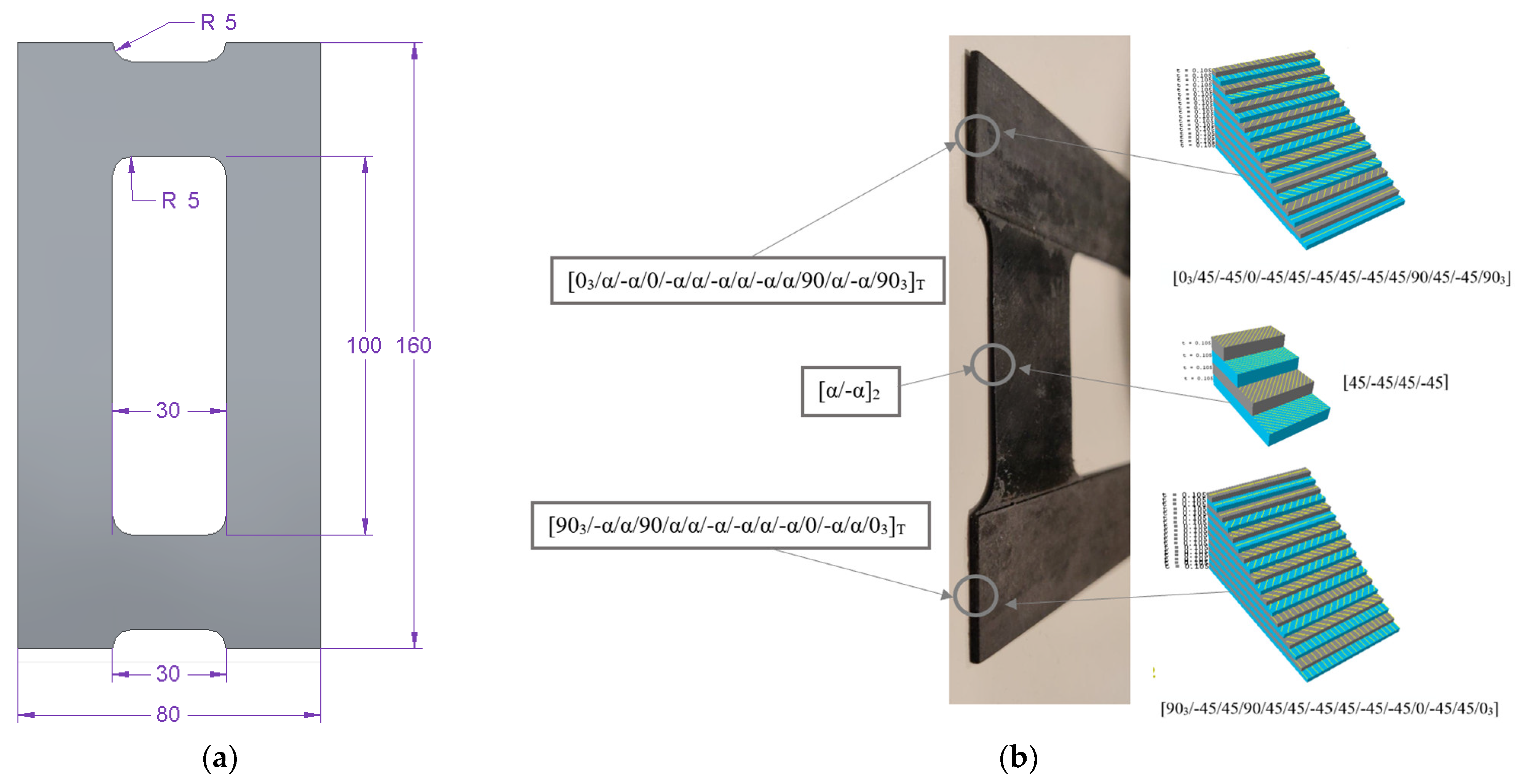
2. Object of the Research
3. Methodology and Scope of the Study
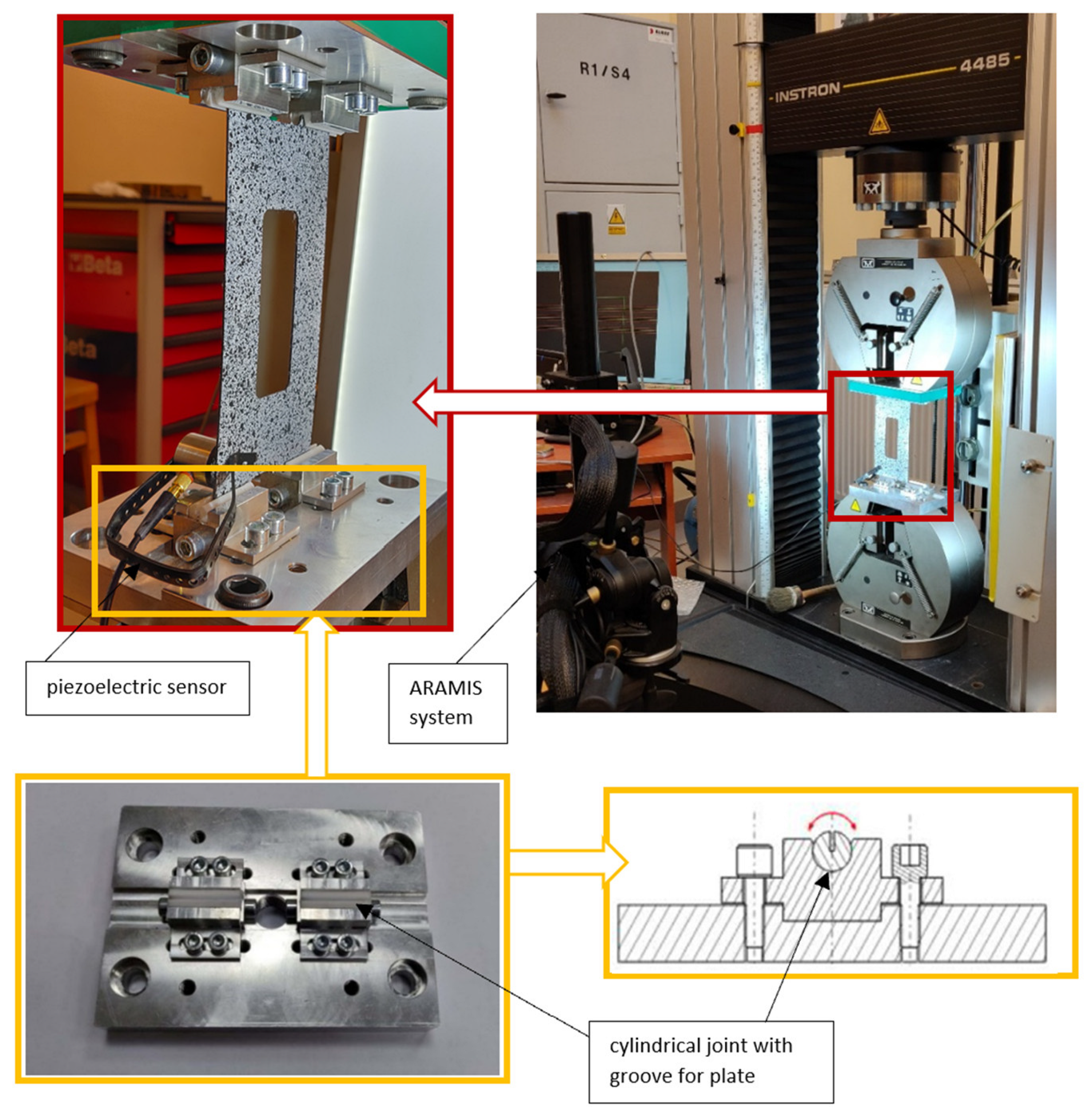
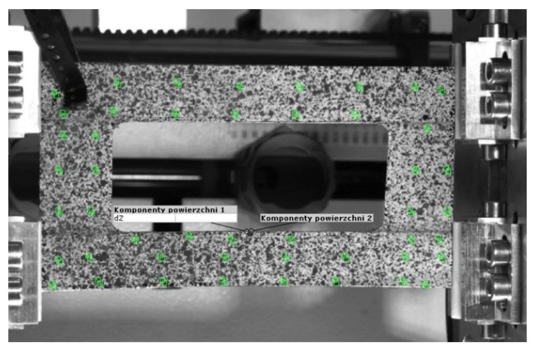
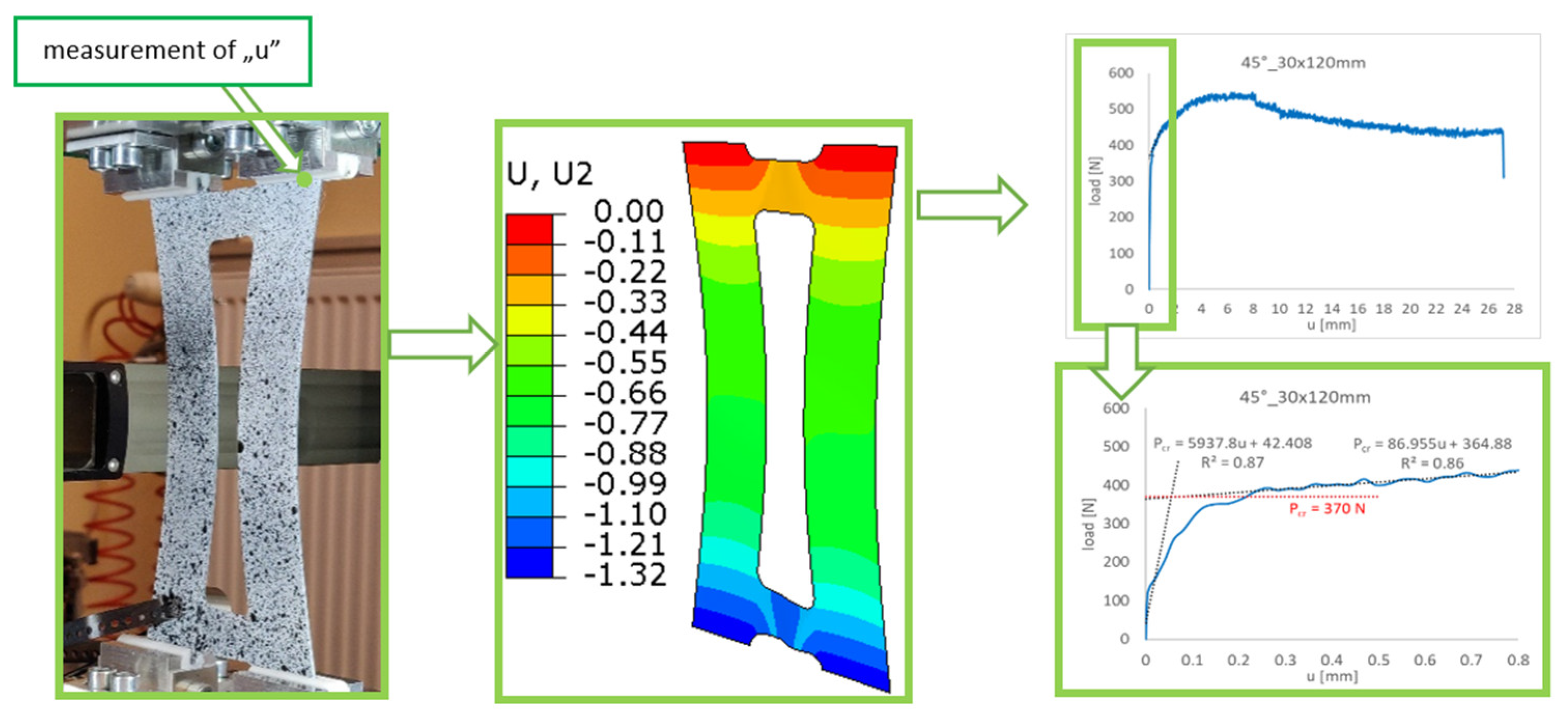
3.1. Experimental
- -
- the values of the strains/main displacements in the specimen;
- -
- changes in the specimen shape during the loading process.
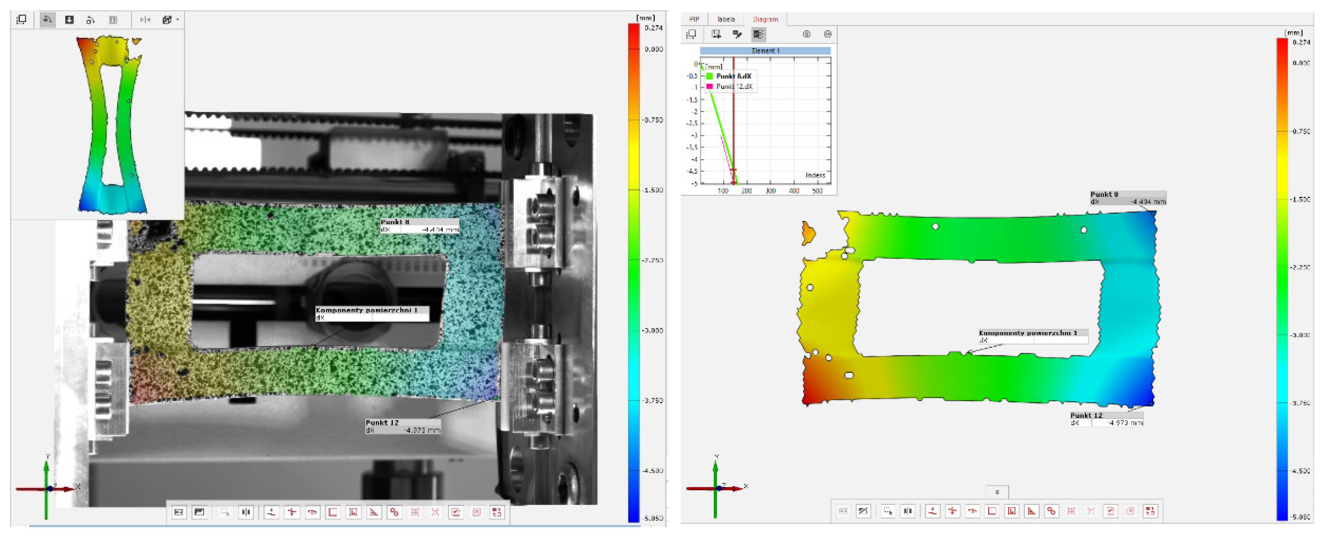
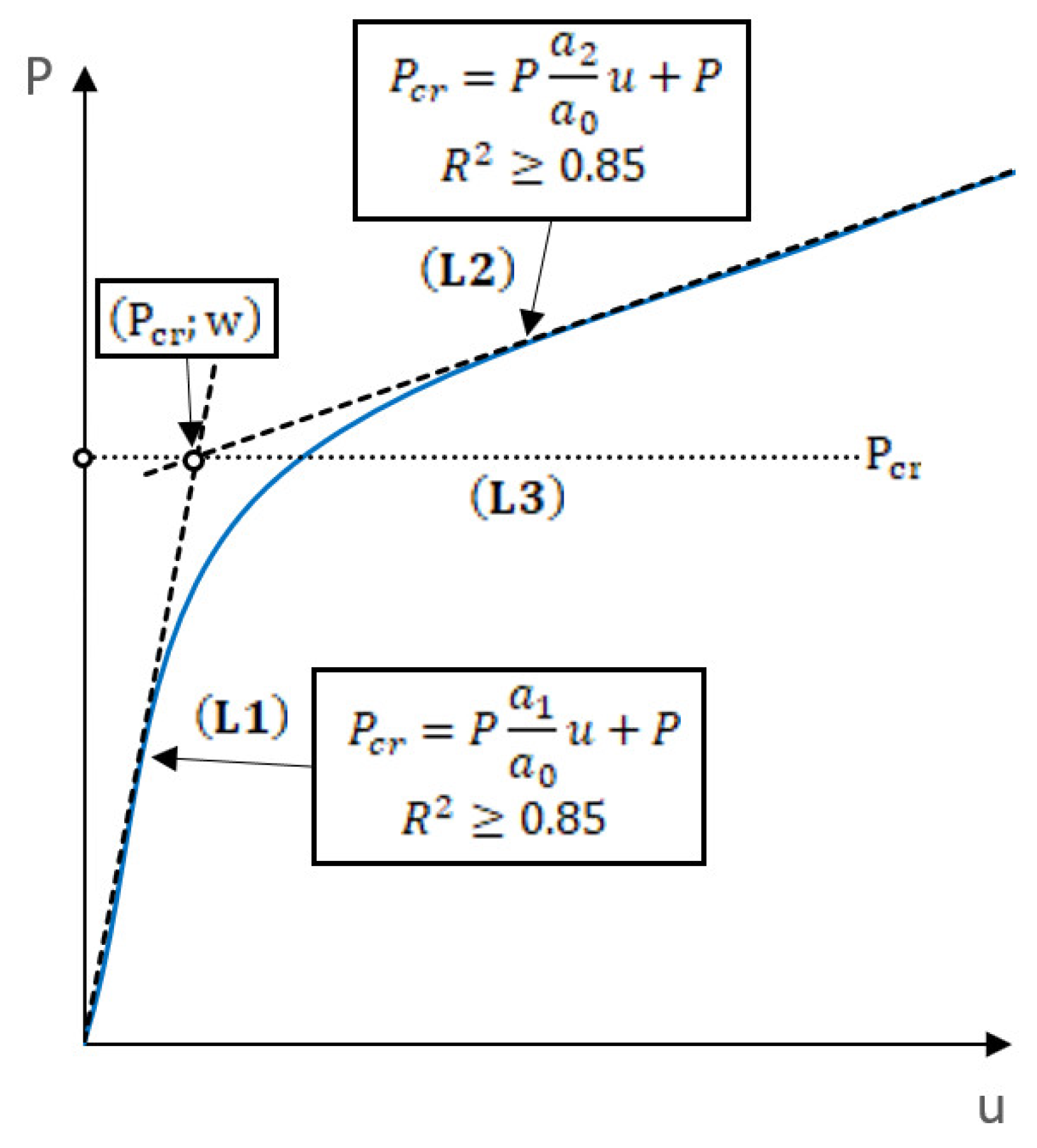
3.2. Experimental Determination of the Buckling Load
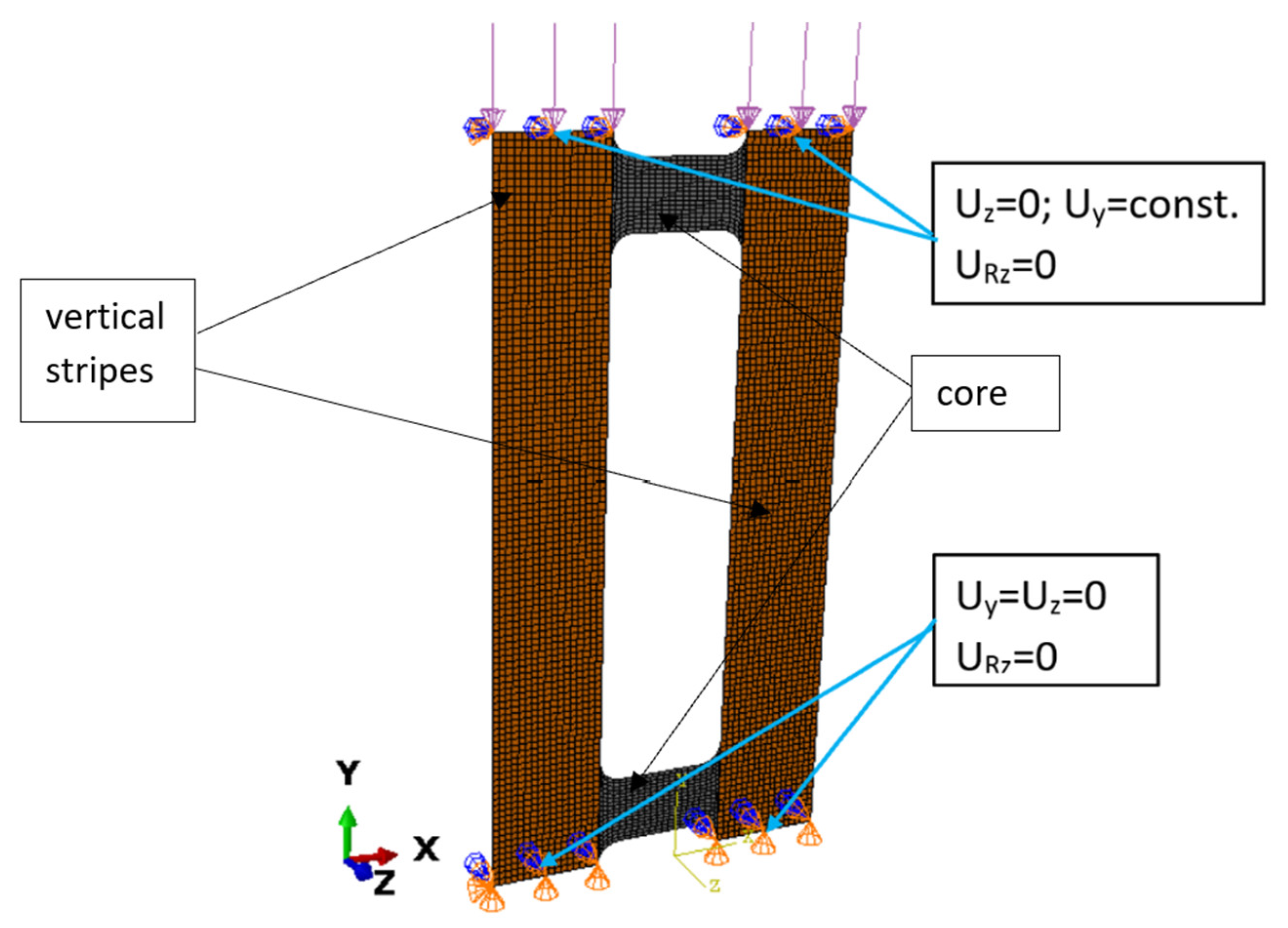
3.3. Numerical Model
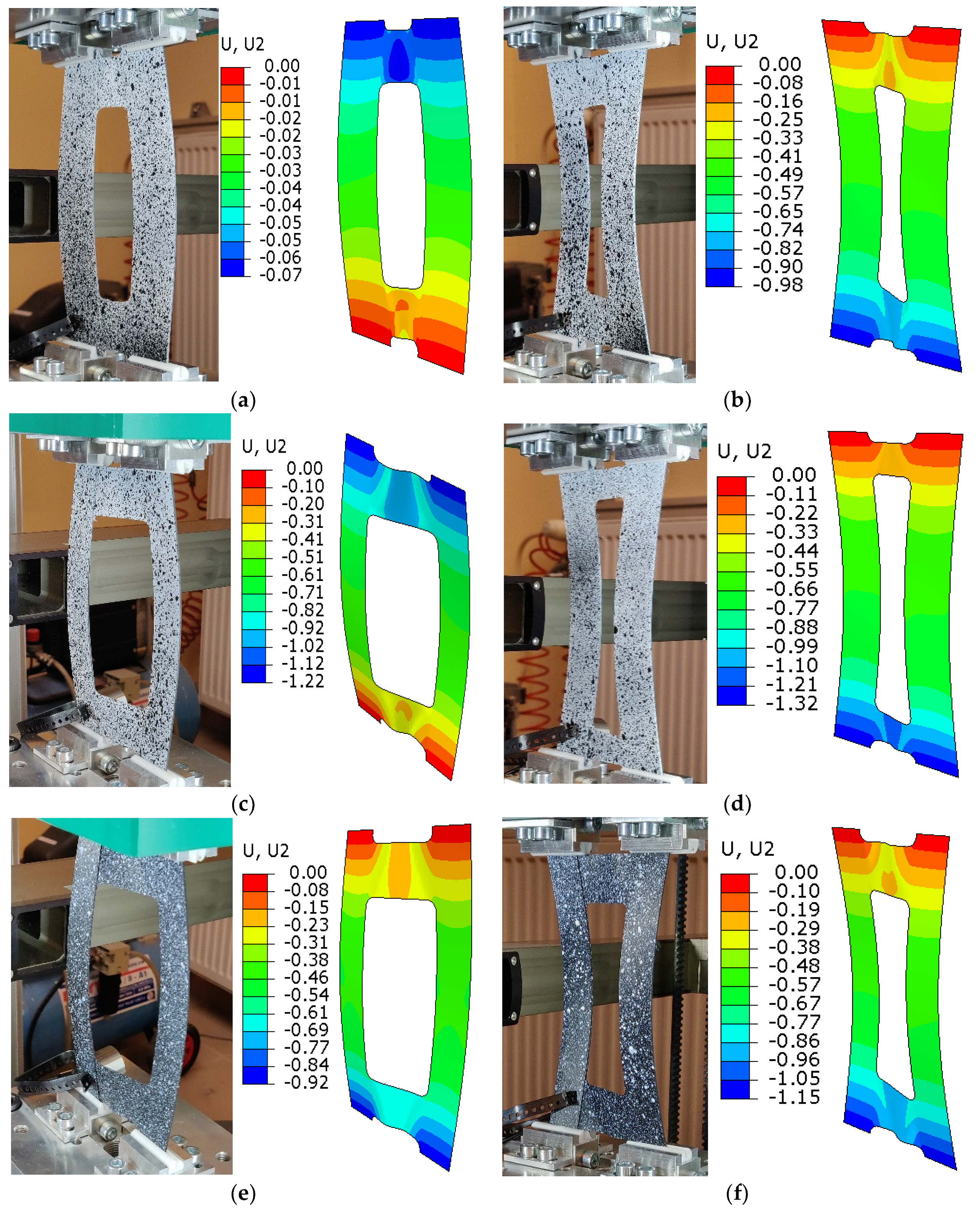
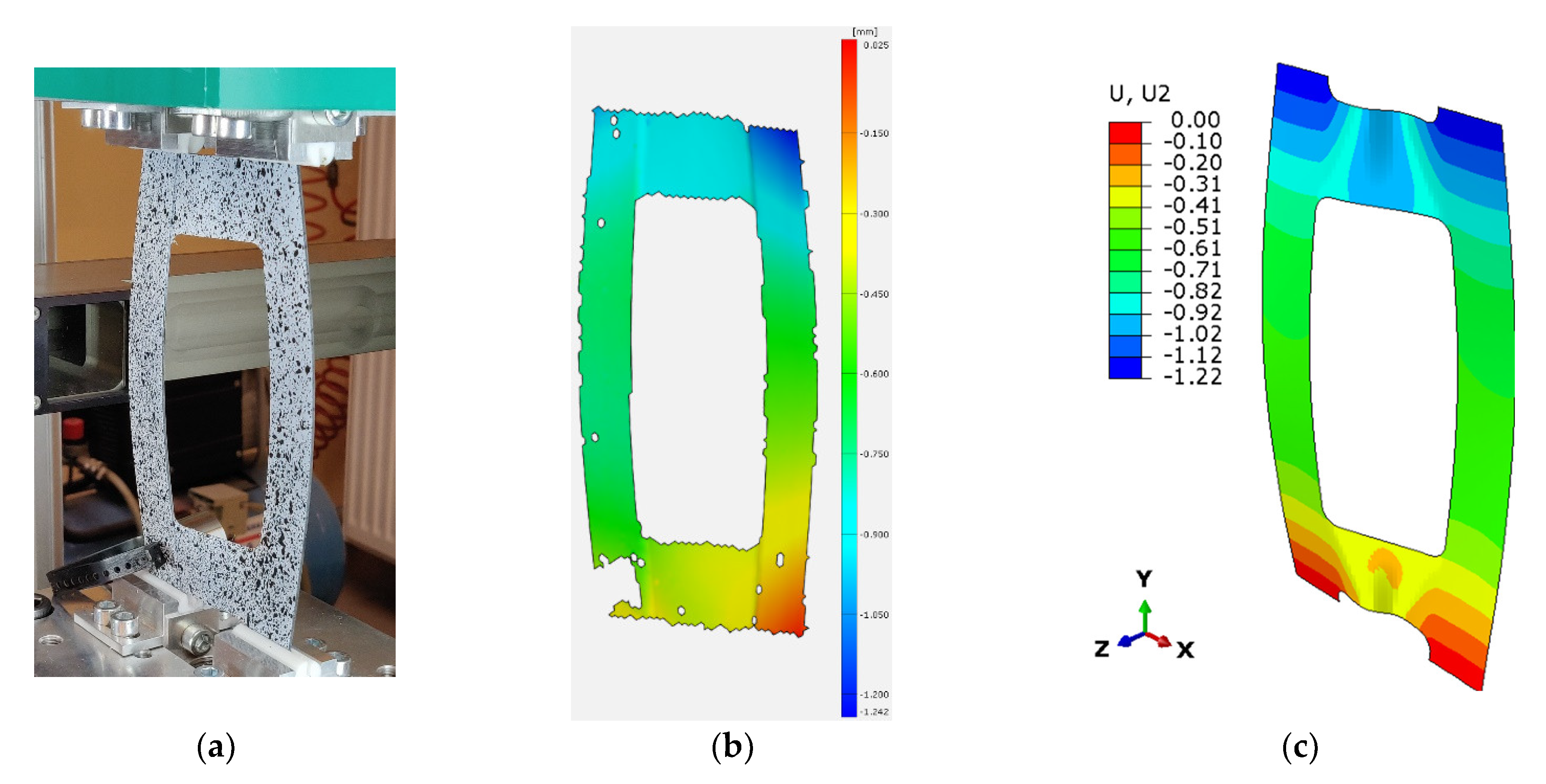
4. Results and Discussion
5. Conclusions
Author Contributions
Funding
Institutional Review Board Statement
Informed Consent Statement
Data Availability Statement
Acknowledgments
Conflicts of Interest
References
- Chróścielewski, J.; Miśkiewicz, M.; Pyrzowski, Ł.; Rucka, M.; Sobczyk, B.; Wilde, K. Modal Properties Identification of a Novel Sandwich Footbridge—Comparison of Measured Dynamic Response and FEA. Compos. Part B Eng. 2018, 151, 245–255. [Google Scholar] [CrossRef]
- Chróścielewski, J.; Miśkiewicz, M.; Pyrzowski, Ł.; Sobczyk, B.; Wilde, K. A Novel Sandwich Footbridge—Practical Application of Laminated Composites in Bridge Design and in Situ Measurements of Static Response. Compos. Part B Eng. 2017, 126, 153–161. [Google Scholar] [CrossRef]
- Carlsson, L.A.; Adams, D.F.; Pipes, R.B. Experimental Characterization of Advanced Composite Materials, 4th ed.; CRC Press: Boca Raton, FL, USA, 2014; ISBN 978-0-429-10939-3. [Google Scholar]
- Parlapalli, M.R.; Soh, K.C.; Shu, D.W.; Ma, G. Experimental Investigation of Delamination Buckling of Stitched Composite Laminates. Compos. Part A Appl. Sci. Manuf. 2007, 38, 2024–2033. [Google Scholar] [CrossRef]
- Turvey, G.J.; Zhang, Y. A Computational and Experimental Analysis of the Buckling, Postbuckling and Initial Failure of Pultruded GRP Columns. Comput. Struct. 2006, 84, 1527–1537. [Google Scholar] [CrossRef]
- Baker, A.A.; Dutton, S.; Kelly, D. (Eds.) Composite Materials for Aircraft Structures, 2nd ed.; Education Series; American Institute of Aeronautics and Astronautics: Reston, VA, USA, 2004; ISBN 978-1-56347-540-5. [Google Scholar]
- Guo, S.; Cheng, W.; Cui, D. Aeroelastic Tailoring of Composite Wing Structures by Laminate Layup Optimization. AIAA J. 2006, 44, 3146–3150. [Google Scholar] [CrossRef]
- Campbell, F.C. Introduction. In Manufacturing Technology for Aerospace Structural Materials; Elsevier: Amsterdam, The Netherlands, 2006; pp. 1–13. ISBN 978-1-85617-495-4. [Google Scholar]
- ASM International (Ed.) ASM Handbook, 10th ed.; ASM International: Materials Park, OH, USA, 1990; ISBN 978-0-87170-377-4. [Google Scholar]
- Tavares, S.M.O.; De Castro, P.M.S.T. Materials. In Damage Tolerance of Metallic Aircraft Structures; Springer Briefs in Applied Sciences and Technology; Springer International Publishing: Cham, Switzerland, 2019; pp. 29–42. ISBN 978-3-319-70189-9. [Google Scholar]
- Kopecki, T.; Mazurek, P.; Lis, T.; Chodorowska, D. Post-Buckling Deformation States of Semi-Monocoque Cylindrical Structures with Large Cut-Outs under Operating Load Conditions. Numerical Analysis and Experimental Tests. EiN 2016, 18, 16–24. [Google Scholar] [CrossRef]
- Singer, J.; Arbocz, J.; Weller, T. Buckling Experiments: Experimental Methods in Buckling of Thin-Walled Structures; John Wiley & Sons, Inc.: New York, NY, USA, 2000; Volume 1, ISBN 978-0-470-17298-8. [Google Scholar]
- Doyle, J.F. Nonlinear Analysis of Thin-Walled Structures: Statics, Dynamics, and Stability; Mechanical Engineering Series; Springer: New York, NY, USA, 2001; ISBN 978-0-387-95216-1. [Google Scholar]
- Khdeir, A.A.; Librescu, L. Analysis of Symmetric Cross-Ply Laminated Elastic Plates Using a Higher-Order Theory: Part II—Buckling and Free Vibration. Compos. Struct. 1988, 9, 259–277. [Google Scholar] [CrossRef]
- Reddy, J.N.; Khdeir, A.A.; Librescu, L. Le’vy Type Solutions for Symmetrically Laminated Rectangular Plates Using First-Order Shear Deformation Theory. J. Appl. Mech. 1987, 54, 740–742. [Google Scholar] [CrossRef]
- Bazant, Z.P.; Cedolin, L.; Hutchinson, J.W. Stability of Structures: Elastic, Inelastic, Fracture, and Damage Theories. J. Appl. Mech. 1993, 60, 567–568. [Google Scholar] [CrossRef]
- Shanmugam, N.E. Openings in Thin-Walled Steel Structures. Thin-Walled Struct. 1997, 28, 355–372. [Google Scholar] [CrossRef]
- Loughlan, J.; Yidris, N.; Cunningham, P.R. The Effects of Local Buckling and Material Yielding on the Axial Stiffness and Failure of Uniformly Compressed I-Section and Box-Section Struts. Thin-Walled Struct. 2011, 49, 264–279. [Google Scholar] [CrossRef]
- Paulo, R.M.F.; Teixeira-Dias, F.; Valente, R.A.F. Numerical Simulation of Aluminium Stiffened Panels Subjected to Axial Compression: Sensitivity Analyses to Initial Geometrical Imperfections and Material Properties. Thin-Walled Struct. 2013, 62, 65–74. [Google Scholar] [CrossRef]
- Taheri-Behrooz, F.; Omidi, M.; Shokrieh, M.M. Experimental and Numerical Investigation of Buckling Behavior of Composite Cylinders with Cutout. Thin-Walled Struct. 2017, 116, 136–144. [Google Scholar] [CrossRef]
- Eiblmeier, J.; Loughlan, J. The Influence of Reinforcement Ring Width on the Buckling Response of Carbon Fibre Composite Panels with Circular Cut-Outs. Compos. Struct. 1997, 38, 609–622. [Google Scholar] [CrossRef]
- Ye, J.; Rasmussen, K.J. Compression Strength of Unstiffened Elements in Cold-Reduced High Strength Steel. J. Struct. Eng. 2008, 134, 189–197. [Google Scholar] [CrossRef]
- Zhong, H.; Gu, C. Buckling of Symmetrical Cross-Ply Composite Rectangular Plates under a Linearly Varying in-Plane Load. Compos. Struct. 2007, 80, 42–48. [Google Scholar] [CrossRef]
- Hu, H.; Badir, A.; Abatan, A. Buckling Behavior of a Graphite/Epoxy Composite Plate under Parabolic Variation of Axial Loads. Int. J. Mech. Sci. 2003, 45, 1135–1147. [Google Scholar] [CrossRef]
- Czapski, P.; Kubiak, T. Influence of Fibre Arrangement on the Buckling Load of Composite Plates—Analytical Solution. Fibres Text. East. Eur. 2015, 23, 92–97. [Google Scholar] [CrossRef] [Green Version]
- Batoz, J.-L.; Bathe, K.-J.; Ho, L.-W. A Study of Three-Node Triangular Plate Bending Elements. Int. J. Numer. Meth. Eng. 1980, 15, 1771–1812. [Google Scholar] [CrossRef]
- Cui, S.; Hao, H.; Cheong, H.K. Numerical Analysis of Dynamic Buckling of Rectangular Plates Subjected to Intermediate-Velocity Impact. Int. J. Impact Eng. 2001, 25, 147–167. [Google Scholar] [CrossRef]
- Kolakowski, Z.; Kowal-Michalska, K. Interactive Buckling Regarding the Axial Extension Mode of a Thin-Walled Channel under Uniform Compression in the First Nonlinear Approximation. Int. J. Solids Struct. 2011, 48, 119–125. [Google Scholar] [CrossRef]
- Kolakowski, Z.; Krolak, M. Modal Coupled Instabilities of Thin-Walled Composite Plate and Shell Structures. Compos. Struct. 2006, 76, 303–313. [Google Scholar] [CrossRef]
- Kubiak, T. Static and Dynamic Buckling of Thin-Walled Plate Structures; Springer International Publishing: Berlin/Heidelberg, Germany, 2013; ISBN 978-3-319-00653-6. [Google Scholar]
- Bohlooly Fotovat, M.; Kubiak, T.; Perlikowski, P. Mixed Mode Nonlinear Response of Rectangular Plates under Static and Dynamic Compression. Thin-Walled Struct. 2023, 184, 110542. [Google Scholar] [CrossRef]
- Vaseghi, O.; Mirdamadi, H.R.; Panahandeh-Shahraki, D. Non-Linear Stability Analysis of Laminated Composite Plates on One-Sided Foundation by Hierarchical Rayleigh–Ritz and Finite Elements. Int. J. Non-Linear Mech. 2013, 57, 65–74. [Google Scholar] [CrossRef]
- Chen, X.; Nie, G.; Wu, Z. Application of Rayleigh-Ritz Formulation to Thermomechanical Buckling of Variable Angle Tow Composite Plates with General in-Plane Boundary Constraint. Int. J. Mech. Sci. 2020, 187, 106094. [Google Scholar] [CrossRef]
- Belardi, V.G.; Fanelli, P.; Vivio, F. Application of the Ritz Method for the Bending and Stress Analysis of Thin Rectilinear Orthotropic Composite Sector Plates. Thin-Walled Struct. 2023, 183, 110374. [Google Scholar] [CrossRef]
- Bažant, Z.P.; Cedolin, L. Stability of Structures Elastic, Inelastic, Fracture and Damage Theories; World Scientific: Singapore; Hackensack, NJ, USA, 2010; ISBN 978-981-4317-04-7. [Google Scholar]
- Falkowicz, K. Numerical Buckling Analysis of Thin-Walled Channel-Section Composite Profiles Weakened by Cut-Outs. Adv. Sci. Technol. Res. J. 2022, 16, 88–96. [Google Scholar] [CrossRef]
- Falkowicz, K.; Valvo, P. Influence of Composite Lay-Up on the Stability of Channel-Section Profiles Weakened by Cut-Outs—A Numerical Investigation. Adv. Sci. Technol. Res. J. 2023, 17, 108–115. [Google Scholar] [CrossRef]
- Alfano, G.; Crisfield, M.A. Finite Element Interface Models for the Delamination Analysis of Laminated Composites: Mechanical and Computational Issues. Int. J. Numer. Meth. Eng. 2001, 50, 1701–1736. [Google Scholar] [CrossRef]
- Kreja, I. A Literature Review on Computational Models for Laminated Composite and Sandwich Panels. Open Eng. 2011, 1, 59–80. [Google Scholar] [CrossRef]
- Kopecki, T.; Święch, Ł. Experimental and Numerical Analysis of Post-Buckling Deformation States of Integrally Stiffened Thin-Walled Components of Load-Bearing Aircraft Structures. J. Theor. Appl. Mech. 2014, 52, 905–915. [Google Scholar] [CrossRef] [Green Version]
- Mania, R.J.; Kolakowski, Z.; Bienias, J.; Jakubczak, P.; Majerski, K. Comparative Study of FML Profiles Buckling and Postbuckling Behaviour under Axial Loading. Compos. Struct. 2015, 134, 216–225. [Google Scholar] [CrossRef]
- Teter, A.; Kolakowski, Z. Coupled Dynamic Buckling of Thin-Walled Composite Columns with Open Cross-Sections. Compos. Struct. 2013, 95, 28–34. [Google Scholar] [CrossRef]
- Rozylo, P.; Falkowicz, K.; Wysmulski, P.; Debski, H.; Pasnik, J.; Kral, J. Experimental-Numerical Failure Analysis of Thin-Walled Composite Columns Using Advanced Damage Models. Materials 2021, 14, 1506. [Google Scholar] [CrossRef]
- Banat, D.; Mania, R. Failure Analysis of Thin-Walled GLARE Members during Buckling and Post-Buckling Response. AIP Conf. Proc. 2019, 2060, 02000. [Google Scholar]
- Banat, D.; Mania, R.J.; Degenhardt, R. Stress State Failure Analysis of Thin-Walled GLARE Composite Members Subjected to Axial Loading in the Post-Buckling Range. Compos. Struct. 2022, 289, 115468. [Google Scholar] [CrossRef]
- Banat, D.; Mania, R.J. Progressive Failure Analysis of Thin-Walled Fibre Metal Laminate Columns Subjected to Axial Compression. Thin-Walled Struct. 2018, 122, 52–63. [Google Scholar] [CrossRef]
- Wysmulski, P.; Debski, H.; Falkowicz, K. Sensitivity of Compressed Composite Channel Columns to Eccentric Loading. Materials 2022, 15, 6938. [Google Scholar] [CrossRef]
- Różyło, P. Failure Analysis of Beam Composite Elements Subjected to Three-Point Bending Using Advanced Numerical Damage Models. Acta Mech. Autom. 2023, 17, 133–144. [Google Scholar] [CrossRef]
- Falkowicz, K.; Debski, H. The Work of a Compressed, Composite Plate in Asymmetrical Arrangement of Layers. AIP Conf. Proc. 2019, 2078, 20005. [Google Scholar]
- Jonak, J.; Karpiński, R.; Wójcik, A. Numerical Analysis of the Effect of Embedment Depth on the Geometry of the Cone Failure. J. Phys. Conf. Ser. 2021, 2130, 012012. [Google Scholar] [CrossRef]
- Jonak, J.; Karpiński, R.; Wójcik, A.; Siegmund, M. Numerical Investigation of the Formation of a Failure Cone during the Pullout of an Undercutting Anchor. Materials 2023, 16, 2010. [Google Scholar] [CrossRef] [PubMed]
- Machrowska, A.; Karpiński, R.; Jonak, J.; Szabelski, J.; Krakowski, P. Numerical prediction of the component-ratio-dependent compressive strength of bone cement. Appl. Comput. Sci. 2020, 16, 88–101. [Google Scholar] [CrossRef]
- Jonak, J.; Karpiński, R.; Siegmund, M.; Wójcik, A.; Jonak, K. Analysis of the Rock Failure Cone Size Relative to the Group Effect from a Triangular Anchorage System. Materials 2020, 13, 4657. [Google Scholar] [CrossRef]
- Rogala, M.; Gajewski, J. Crashworthiness Analysis of Thin-Walled Square Columns with a Hole Trigger. Materials 2023, 16, 4196. [Google Scholar] [CrossRef] [PubMed]
- Nikopour, H.; Selvadurai, A.P.S. Concentrated Loading of a Fibre-Reinforced Composite Plate: Experimental and Computational Modeling of Boundary Fixity. Compos. Part B Eng. 2014, 60, 297–305. [Google Scholar] [CrossRef]
- Chrysanidis, T. Experimental and Numerical Research on Cracking Characteristics of Medium-Reinforced Prisms under Variable Uniaxial Degrees of Elongation. Eng. Fail. Anal. 2023, 145, 107014. [Google Scholar] [CrossRef]
- Falkowicz, K. Composite Plate Analysis Made in an Unsymmetric Configuartion. J. Phys. Conf. Ser. 2021, 2130, 012014. [Google Scholar] [CrossRef]
- Falkowicz, K. Experimental and Numerical Analysis of Compression Thin-Walled Composite Plates Weakened by Cut-Outs. Arch. Civ. Eng. 2017, 63, 161–172. [Google Scholar] [CrossRef]
- Van der Heijden, A.M.A. W. T. Koiter’s Elastic Stability of Solids and Structures; Cambridge University Press: Cambridge, UK, 2012; ISBN 978-1-107-40701-5. [Google Scholar]
- Coan, J.M. Large-Deflection Theory for Plates With Small Initial Curvature Loaded in Edge Compression. J. Appl. Mech. 1951, 18, 143–151. [Google Scholar] [CrossRef]
- Roorda, J.; Venkataramaiah, K.R. Analysis of Local Plate Buckling Experimental Data. In Proceedings of the 6th International Specialty Conference on Cold-Formed Steel Structures, St. Louis, MO, USA, 16–17 November 1982. [Google Scholar]
- Bienias, J.; Gliszczynski, A.; Jakubczak, P.; Kubiak, T.; Majerski, K. Influence of Autoclaving Process Parameters on the Buckling and Postbuckling Behaviour of Thin-Walled Channel Section Beams. Thin-Walled Struct. 2014, 85, 262–270. [Google Scholar] [CrossRef]
- Różyło, P.; Smagowski, W.; Paśnik, J. Experimental Research in the Aspect of Determining the Mechanical and Strength Properties of the Composite Material Made of Carbon-Epoxy Composite. Adv. Sci. Technol. Res. J. 2023, 17, 232–246. [Google Scholar] [CrossRef]
- Falkowicz, K.; Szklarek, K. Analytical Method for Projecting the Buckling Form of Composite Palates with a Cut-Out. IOP Conf. Ser. Mater. Sci. Eng. 2019, 710, 012021. [Google Scholar] [CrossRef]
- York, C.B. On Tapered Warp-Free Laminates with Single-Ply Terminations. Compos. Part A Appl. Sci. Manuf. 2015, 72, 127–138. [Google Scholar] [CrossRef] [Green Version]
- York, C. Unified Approach to the Characterization of Coupled Composite Laminates: Hygro-thermally Curvature-stable Configurations. Int. J. Struct. Integr. 2011, 2, 406–436. [Google Scholar] [CrossRef]
- Falkowicz, K. Experimental and Numerical Failure Analysis of Thin-Walled Composite Plates Using Progressive Failure Analysis. Compos. Struct. 2023, 305, 116474. [Google Scholar] [CrossRef]
- Falkowicz, K.; Samborski, S.; Valvo, P.S. Effects of Elastic Couplings in a Compressed Plate Element with Cut-Out. Materials 2022, 15, 7752. [Google Scholar] [CrossRef]
- Falkowicz, K.; Debski, H.; Wysmulski, P. Effect of Extension-Twisting and Extension-Bending Coupling on a Compressed Plate with a Cut-Out. Compos. Struct. 2020, 238, 111941. [Google Scholar] [CrossRef]
- Lusiak, T.; Knec, M. Use of ARAMIS for Fatigue Process Control in the Accelerated Test for Composites. Transp. Res. Procedia 2018, 35, 250–258. [Google Scholar] [CrossRef]
- Falkowicz, K. Validation of Extension-Bending and Extension-Twisting Coupled Laminates in Elastic Element. Adv. Sci. Technol. Res. J. 2023, 17, 309–319. [Google Scholar] [CrossRef]
- Paszkiewicz, M.; Kubiak, T. Selected Problems Concerning Determination of the Buckling Load of Channel Section Beams and Columns. Thin-Walled Struct. 2015, 93, 112–121. [Google Scholar] [CrossRef]
- Falkowicz, K.; Ferdynus, M.; Rozylo, P. Experimental and Numerical Analysis of Stability and Failure of Compressed Composite Plates. Compos. Struct. 2021, 263, 113657. [Google Scholar] [CrossRef]
- Rozylo, P.; Falkowicz, K. Stability and Failure Analysis of Compressed Thin-Walled Composite Structures with Central Cut-out, Using Three Advanced Independent Damage Models. Compos. Struct. 2021, 273, 114298. [Google Scholar] [CrossRef]


| Young’s Modulus [MPa] | Poisson’s Ratio ν12 | Kirchhoff’s Modulus G12 [MPa] | |
|---|---|---|---|
| 0° (E1) | 90° (E2) | 0.36 | ±45° |
| 143,530 | 5826 | 3845 | |
| Ply Number | Core | Strips | Final Configuration | |||
|---|---|---|---|---|---|---|
| Ply Orientation | Coupling | Ply Orientation | Coupling | Configuration | Coupling | |
| 18 | [α/−α]2 | ASBtDS * | [α/−α/0/−α/0/α/90/α/−α] | ASBlDS * | [03/α/−α/0/−α/α/−α/α/−α/α/90/α/−α/903]T | ASBltDS |
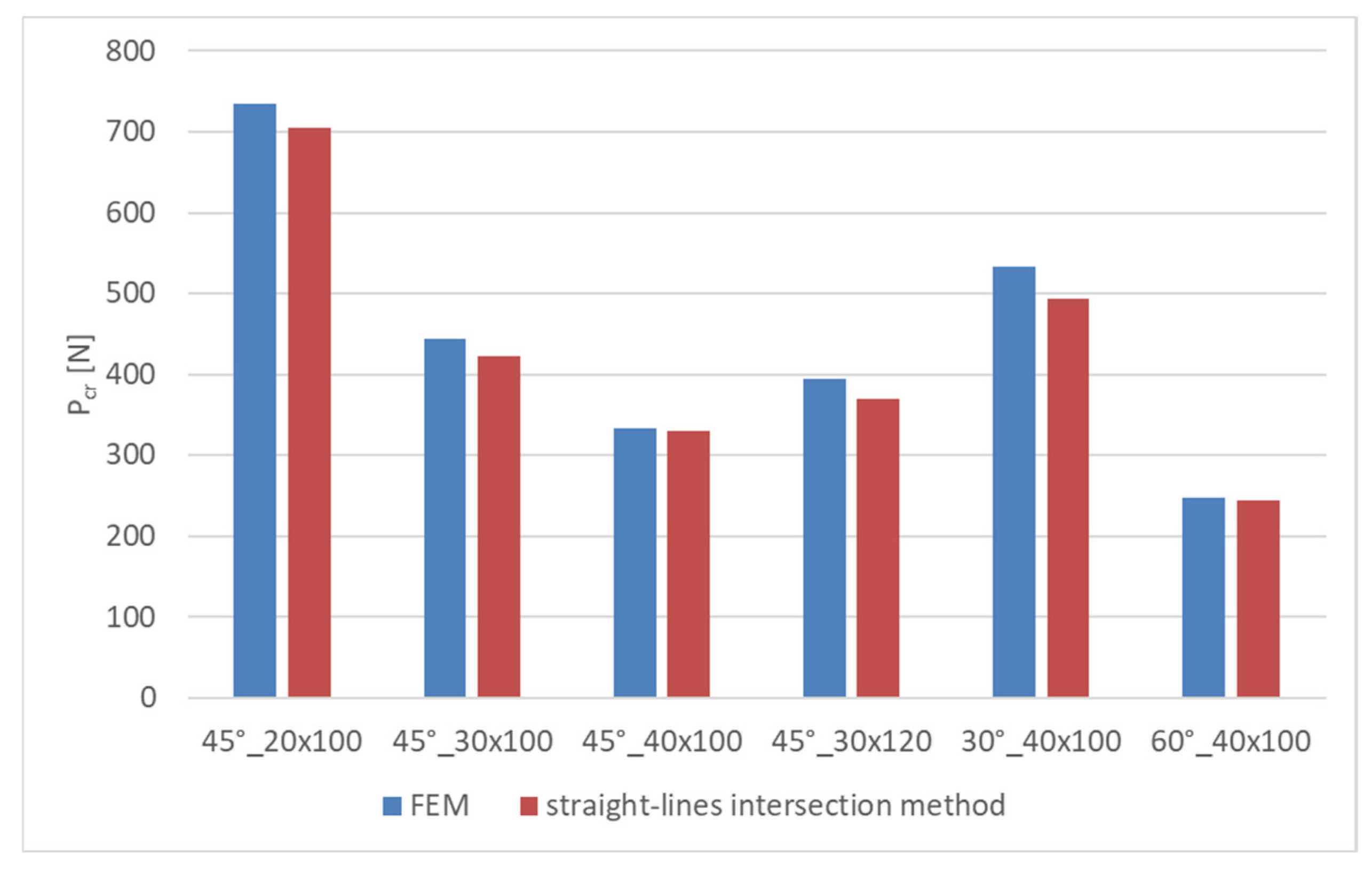
| Method | 45°_20 × 100 | 45°_30 × 100 | 45°_40 × 100 | 45°_30 × 120 | 30°_40 × 100 | 60°_40 × 100 |
|---|---|---|---|---|---|---|
| FEM [N] | 735 | 444 | 333 | 394 | 533 | 247 |
| straight-lines intersection [N] | 705 | 422 | 330 | 370 | 494 | 244 |
| Difference [N] | 20 | 22 | 3 | 24 | 39 | 3 |
| Difference [%] | 45°_20 × 100 | 45°_30 × 100 | 45°_40 × 100 | 45°_30 × 120 | 30°_40 × 100 | 60°_40 × 100 |
|---|---|---|---|---|---|---|
| FEM/ straight-lines intersection | 4.08% | 4.95% | 0.9% | 6.09% | 7.32% | 1.21% |
Disclaimer/Publisher’s Note: The statements, opinions and data contained in all publications are solely those of the individual author(s) and contributor(s) and not of MDPI and/or the editor(s). MDPI and/or the editor(s) disclaim responsibility for any injury to people or property resulting from any ideas, methods, instructions or products referred to in the content. |
© 2023 by the authors. Licensee MDPI, Basel, Switzerland. This article is an open access article distributed under the terms and conditions of the Creative Commons Attribution (CC BY) license (https://creativecommons.org/licenses/by/4.0/).
Share and Cite
Falkowicz, K.; Wysmulski, P.; Debski, H. Buckling Analysis of Laminated Plates with Asymmetric Layup by Approximation Method. Materials 2023, 16, 4948. https://doi.org/10.3390/ma16144948
Falkowicz K, Wysmulski P, Debski H. Buckling Analysis of Laminated Plates with Asymmetric Layup by Approximation Method. Materials. 2023; 16(14):4948. https://doi.org/10.3390/ma16144948
Chicago/Turabian StyleFalkowicz, Katarzyna, Pawel Wysmulski, and Hubert Debski. 2023. "Buckling Analysis of Laminated Plates with Asymmetric Layup by Approximation Method" Materials 16, no. 14: 4948. https://doi.org/10.3390/ma16144948