

Study on Flexural Behavior of Corroded I-Shaped Steel Beams Strengthened with Hybrid CFRP/GFRP Sheets
Abstract
:1. Introduction
2. Materials and Methods
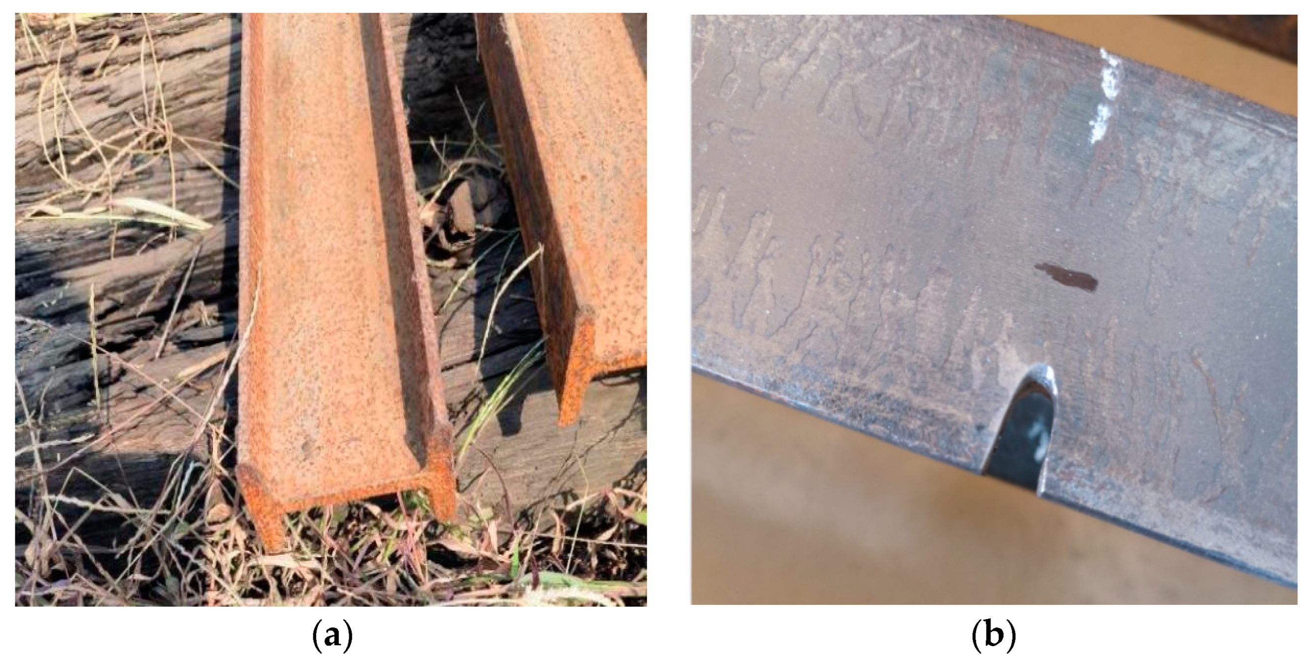
2.1. Test Piece Processing
2.2. Material Properties

| Testing Items | Testing Basis | Detection Result |
|---|---|---|
| Tensile Strength | National Standard [20] | 56.2 MPa |
| Tensile Modulus of Elasticity | 2932 MPa | |
| Elongation | 2.33% | |
| Bending Strength | 89.5 MPa, and there is no fragmented damage | |
| Compressive Strength | 81.0 MPa |
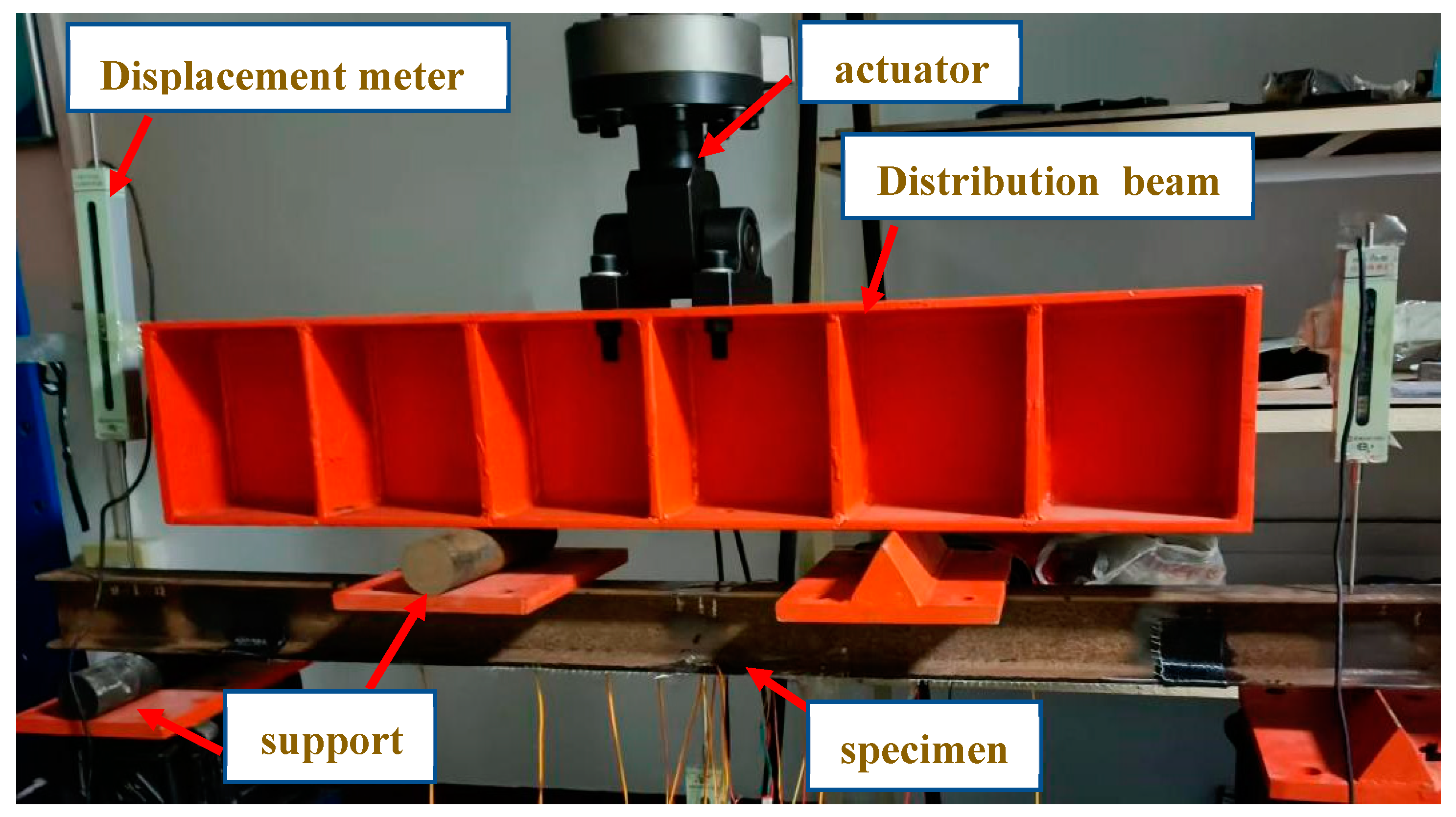
2.3. Loading Device
3. Test Results
3.1. Failure Model
3.2. The Influence of GFRP Fabric Reinforcement Layers
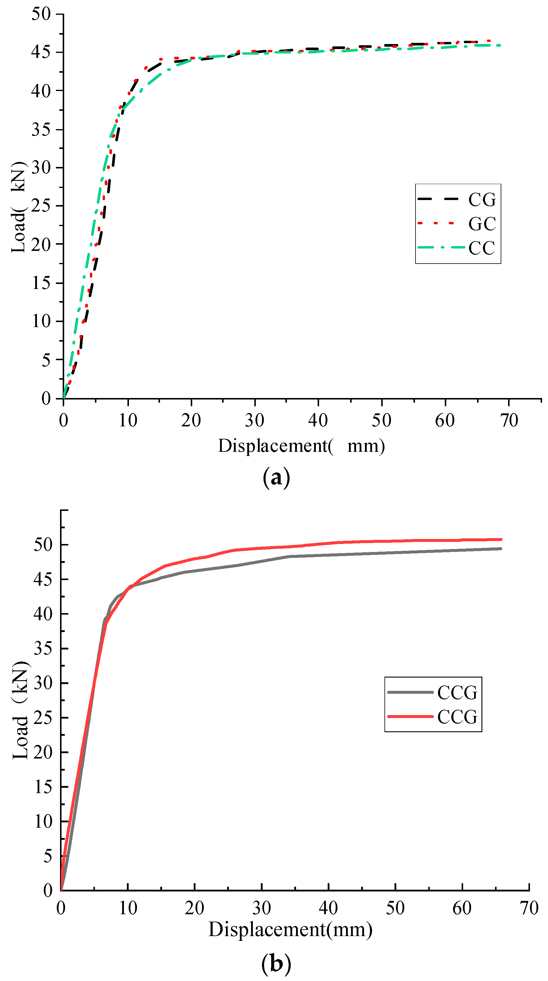
3.3. The Influence of Interlayer Mixed Layering Order
3.4. Comparison of Reinforcement Effects of GFRP Fabric Partially Replacing CFRP Fabric
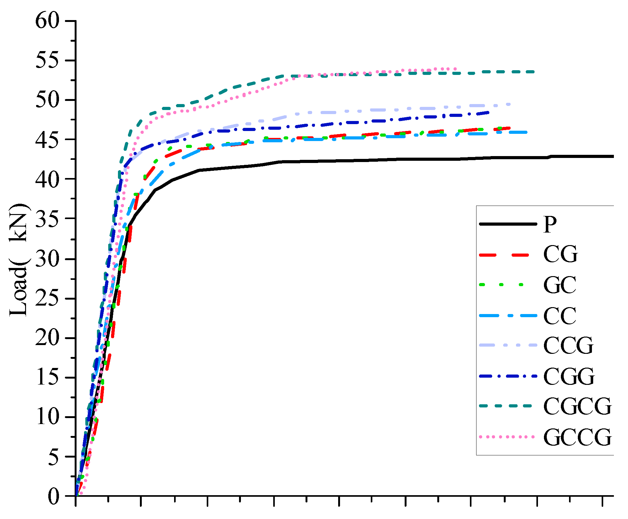
3.5. Comprehensive Analysis of the Experiment
4. Numerical Simulation of Mixed Reinforcement of Corroded I-Shaped Steel Beams with CFRP/GFRP Sheets
4.1. Model Building
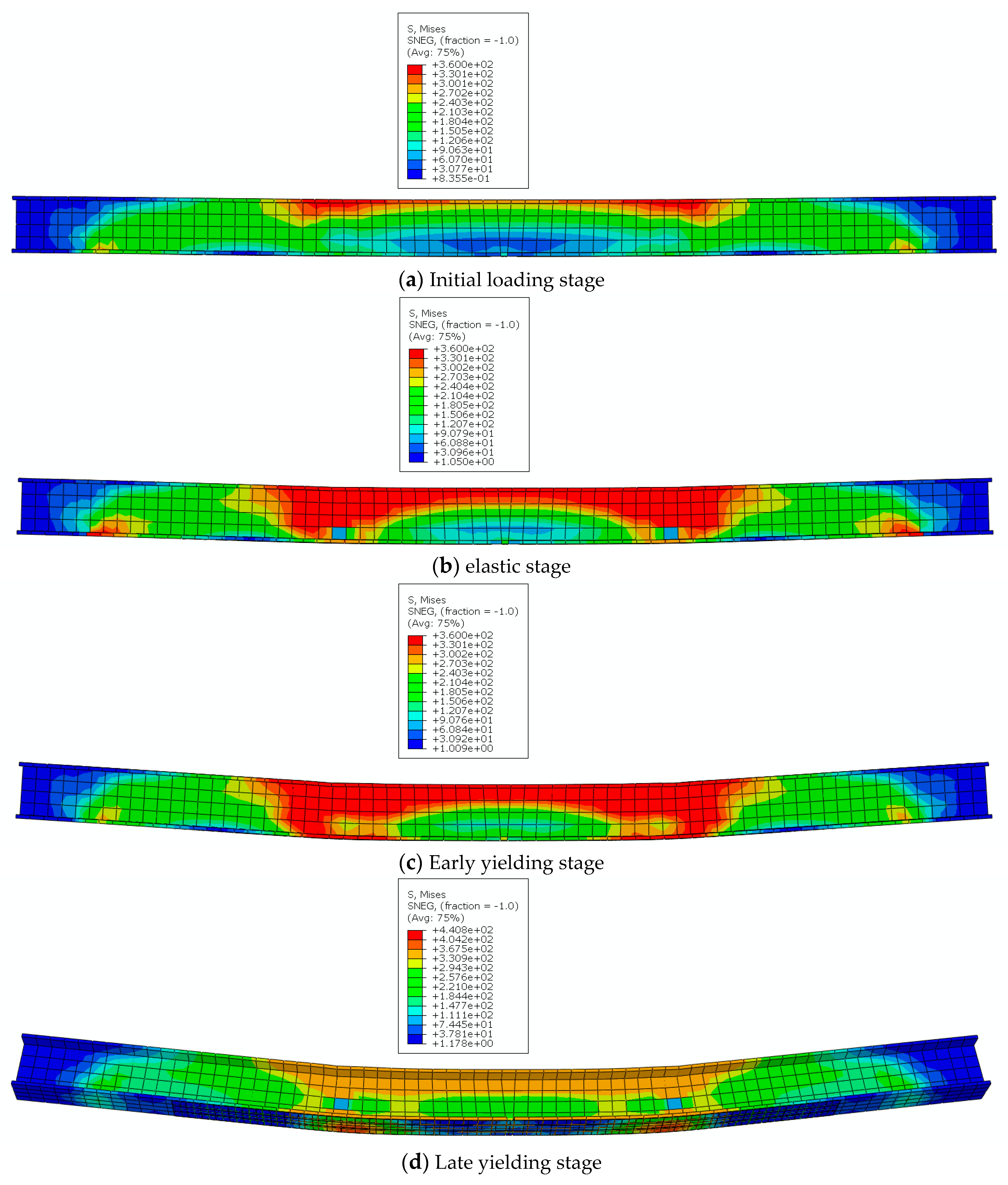
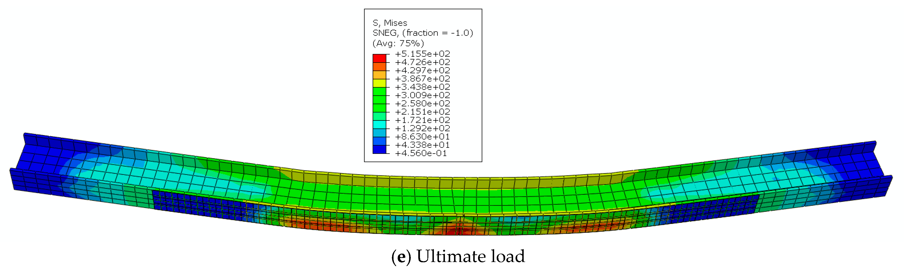
4.2. Stress Nephogram
4.3. Stress Process Analysis
5. Conclusions
- (1)
- Based on the experimental failure phenomena of 8 test beams, 2 failure modes were identified, namely the middle section torsion instability failure of the steel beam and the fracture and detachment of the CFRP/GFRP cloth from the steel beam.
- (2)
- The overall strain value of the reinforced beam increases continuously with the increase of load. After the steel beam enters the yield stage, significant bending deformation occurs in the mid-span area, where the maximum tensile stress of CFRP/GFRP fabric is concentrated here. Therefore, the fracture and peel failure of CFRP/GFRP fabric also occur here.
- (3)
- The number of CFRP/GFRP reinforcement layers is the most important factor affecting the reinforcement effect. Compared to the unreinforced beam, the yield load increase rate of the 2-layer CFRP/GFRP fabric is between 2.78% and 5.95%, and the ultimate load increase rate is between 7.23% and 8.65%. The reinforcement effect of 3-layer CFRP/GFRP fabric increase rates ranging from 12.31% to 13.58%, and ultimate load increase rates ranging from 12.88% to 15.28%.The effect of 4-layer CFRP/GFRP fabric has been significantly improved, with yield load increase rates ranging from 17.68% to 20.19%, and ultimate load increase rates ranging from 25.03% to 27.34%.
- (4)
- When the number of CFRP reinforcement layers is the same, the number of GFRP reinforcement layers is directly proportional to the yield load and ultimate load of the reinforced beam. GFRP fabric effectively suppresses the plastic development of the tensile zone of the specimen and improves the flexural bearing capacity of the corroded I-shaped steel beam.
Author Contributions
Funding
Institutional Review Board Statement
Informed Consent Statement
Data Availability Statement
Acknowledgments
Conflicts of Interest
Nomenclature
| Symbol | Name |
| E | Elastic modulus |
| Nu | Poisson’s ratio |
| G | shear modulus |
References
- Albrecht, P.; Hall, T.T., Jr. Atmospheric Corrosion Resistance of Structural Steels. J. Mater. Civ. Eng. 2003, 15, 2–4. [Google Scholar] [CrossRef]
- Yu, Z. State Assessment and Fatigue Life Prediction of Composite Steel Bridge Structures Based on Corrosion Damage; Chang’an University: Xi’an, China, 2007. [Google Scholar]
- Nassiraei, H.; Rezadoost, P. SCFs in tubular X-connections retrofitted with FRP under in-plane bending load. Compos. Struct. 2021, 274, 114314. [Google Scholar] [CrossRef]
- Nassiraei, H.; Rezadoost, P. SCFs in tubular X-joints retrofitted with FRP under out-of-plane bending moment. Mar. Struct. 2021, 79, 103010. [Google Scholar] [CrossRef]
- Zhao, J.; Luo, X.; Wang, Z.; Feng, S.; Gong, X.; Shumuye, E.D. Experimental Study on Bond Performance of Carbon- and Glass-Fiber Reinforced Polymer (CFRP/GFRP) Bars and Steel Strands to Concrete. Materials 2021, 14, 1268. [Google Scholar] [CrossRef]
- Kim, J.S.; Kim, S.J.; Min, K.J.; Choi, J.C.; Eun, H.S.; Song, B.K. A Study on Tensile Behavior According to the Design Method for the CFRP/GFRP Grid for Reinforced Concrete. Materials 2022, 15, 357. [Google Scholar] [CrossRef]
- Wang, Y.; Wu, J. Flexural Behavior of Corroded Concrete Beams Strengthened with Carbon Fiber-Reinforced Polymer. Materials 2023, 16, 4355. [Google Scholar] [CrossRef]
- Zhang, T.; Dan, Y.G. Tensile behavior analysis and prediction of steel fiber-reinforced-carbon/glass hybrid composite bars. J. Build. Eng. 2023, 64, 105669. [Google Scholar] [CrossRef]
- Xia, Y.; Du, Q.; Xian, G.; Xia, Y.; Zhu, Y. Durability study of flax fiber and basalt fiber hybrid panels under 98% humidity environment. Munic. Technol. 2021, 39, 129–133. [Google Scholar]
- Attari, N.; Amziane, S.; Chemrouk, M. Flexural strengthening of concrete beams using CFRP, GFRP and hybrid FRP sheets. Constr. Build. Mater. 2012, 37, 746–757. [Google Scholar] [CrossRef]
- Ostapiuk, M.; Bieniaś, J. Fracture Analysis and Shear Strength of Aluminum/CFRP and GFRP Adhesive Joint in Fiber Metal Laminates. Materials 2020, 13, 7. [Google Scholar] [CrossRef] [Green Version]
- Zhang, L.; Zhang, X. Comparative experimental study on CFRP and GFRP reinforcement and repair of steel beams. J. Hefei Univ. Technol. (Nat. Sci. Ed.) 2009, 32, 1253–1255+1259. [Google Scholar]
- He, X.; Guo, X.; Li, Y.; Shen, Q. Mechanism of crack resistance and reinforcement of GFRP/CFRP hybrid reinforced concrete beams. J. Huazhong Univ. Sci. Technol. (Nat. Sci. Ed.) 2014, 42, 78–83. [Google Scholar]
- Mao, D. Comparative experimental study on reinforced concrete beams strengthened with bonded CFRP/GFRP. J. Henan Univ. Technol. (Nat. Sci. Ed.) 2014, 33, 804–809. [Google Scholar]
- Zhang, X.; Deng, Z.; Wang, Y.; Huang, Y. Experimental study on the reinforcement of concrete beams and columns with interlayer hybrid fiber cloth. J. Appl. Fundam. Eng. Sci. 2012, 20, 93–102. [Google Scholar]
- Deng, Z.; Li, J. Flexural performance of corroded beams strengthened with carbon/aramid/glass interlayer hybrid fiber cloth. J. Beijing Univ. Technol. 2009, 35, 338–344. [Google Scholar]
- Wei, J.; Du, Y.; Liang, J.; Huang, D.; Chen, T. Experimental Study on the Effect of Various Fiber Interlayer Hybrid Adhesion on the Ductility of Reinforced Concrete Beams. J. Railw. Sci. Eng. 2019, 16, 1282–1290. [Google Scholar]
- Hou, W.; Wang, L. Experimental study on the flexural performance of corroded steel beams strengthened with prestressed CFRP sheets under overload. J. Northeast. Univ. (Nat. Sci. Ed.) 2018, 39, 1342–1347. [Google Scholar]
- Li, A.; Xu, S.; Wang, Y.; Wu, C.; Nie, B. Fatigue behavior of corroded steel plates strengthened with CFRP plates. Constr. Build. Mater. 2022, 314(Part B), 125707. [Google Scholar] [CrossRef]
- GB/T 2567-2008; Test Method for Properties of Resin Casting Body. Standardization Administration of China: Beijing, China, 2008.
- Yue, Q.; Zhang, N.; Peng, F.; Zheng, Y. Research on the Performance and Engineering Application of Carbon Fiber Reinforced Composite (CFRP) for Strengthening and Repairing Steel Structures; China Construction Industry Press: Beijing, China, 2009. [Google Scholar]
- Bielak, J.; Schmidt, M.; Hegger, J. Structural Behavior of Large-Scale I-Beams with Combined Textile and CFRP Reinforcement. Appl. Sci. 2020, 10, 4625. [Google Scholar] [CrossRef]
- Guo, X.; Wu, Z.; Yang, Y.; Bai, J. A Study on the Bond–Slip Relationship of the CFRP–Steel Interface of CFRP Strengthened Steel. Materials 2022, 15, 4187. [Google Scholar] [CrossRef]
- Chen, S. Nonlinear Finite Element Analysis of RC Beams Strengthened with CFRP; Wuhan University of Technology: Wuhan, China, 2008. [Google Scholar]
- Wang, W. Nonlinear Finite Element Numerical Simulation Analysis of CFRP Reinforced I-Steel Beams; Hefei University of Technology: Hefei, China, 2009. [Google Scholar]
- Gao, T. Experimental Study and Finite Element Analysis of Reinforced Concrete Beams Strengthened with CFRP; Chang’an University: Xi’an, China, 2009. [Google Scholar]
- Zhao, F.; Niu, Z.; Lu, D.; Yan, Y. Finite element analysis of CFRP reinforced welded I-shaped steel beams. Steel Struct. 2009, 24, 32–35. [Google Scholar]
- Zhang, W. Finite Element Analysis and Shear Bearing Capacity Study of CFRP Reinforced Masonry Experimental Research; Wuhan University of Technology: Wuhan, China, 2007. [Google Scholar]
- Zhang, Z.; Li, T. Deformation Performance of CFRP-Strengthened Corroded Reinforced Concrete Beams after Fatigue Loading. Appl. Sci. 2023, 13, 6198. [Google Scholar] [CrossRef]
- Liu, T.; Xu, X.; Chen, L. Numerical Analysis on Dynamic Response of CFRP-Wrapped RC Columns under Lateral Impact Loading. Materials 2023, 16, 2425. [Google Scholar] [CrossRef] [PubMed]


| Number | Interlayer Mixed Layer | Number | Interlayer Mixed Layer |
|---|---|---|---|
| P | 0 layer CFRP/0 layer GFRP | CGG | 1 layer CFRP/2 layers GFRP |
| CC | 2-layer CFRP | CCG | 2 layers of CFRP/1 layer of GFRP |
| CG | 0 layer CFRP/0 layer GFRP | CGCG | 1 layer CFRP/1 layer GFRP/1 layer CFRP/1 layer GFRP |
| GC | 1 layer GFRP/1 layer CFRP | GCCG | 1 layer GFRP/2 layers CFRP/1 layer GFRP |
| Number | Quality | Quality after Rusting | Mass Loss (%) | Number | Quality | Quality after Rusting | Mass Loss (%) |
|---|---|---|---|---|---|---|---|
| (kg) | (kg) | (kg) | (kg) | ||||
| P | 10.41 | 10.04 | 3.55% | CGG | 10.42 | 9.97 | 4.32% |
| CC | 10.44 | 9.98 | 4.41% | CCG | 10.47 | 9.99 | 4.58% |
| CG | 10.43 | 9.95 | 4.60% | CGCG | 10.43 | 10.03 | 3.84% |
| GC | 10.46 | 10.06 | 3.82% | GCCG | 10.43 | 10.11 | 3.07% |
| FRP Type | Nominal Thickness (mm) | Performance Parameter | |
|---|---|---|---|
| Project | Performance Parameter | ||
| Carbon fiber cloth | 0.167 | tensile strength (MPa) | 3468 |
| Tensile modulus of elasticity (MPa) | 2.31 × 10⁵ | ||
| tensile elongation at break (%) | 1.74 | ||
| Glass fiber cloth | 0.167 | tensile strength (MPa) | 3356 |
| Tensile modulus of elasticity (MPa) | 8.71 × 10⁴ | ||
| tensile elongation at break (%) | 5.3 | ||
| Test Piece Number | Destruction Mode |
|---|---|
| P | During the loading process of the steel beam, the upper and lower flanges of the span buckled and deformed forward, resulting in the instability of the specimen and the inability to load. |
| CC | The CFRP/GFRP fabric broke at the anchorage and detached from the steel beam. |
| CG | Part of the fibers in the middle of the CFRP/GFRP fabric are broken, and the CFRP/GFRP fabric is detached from the steel beam. |
| GC | The CFRP/GFRP fabric on one side of the steel beam is broken, the CFRP fabric is detached from the GFRP fabric, and the inner layer of GFRP fabric is not completely pulled apart. |
| CGG | The middle part of the CFRP/GFRP fabric is detached from the steel beam, and there is a peeling phenomenon between one side of the U-shaped hoop and the web plate. |
| CCG | The CFRP/GFRP fabric breaks and detaches from the steel beam, causing a sudden increase in the degree of buckling and bending at the upper flange of the steel beam span, resulting in the instability of the steel beam. |
| CGCG | The outer GFRP fiber at one edge experienced partial fiber breakage and cracking, with some CFRP/GFRP cloth detached from the steel beam and the specimen damaged. |
| GCCG | Multiple fiber fractures and detachment occurred, and the middle of the CFRP/GFRP fabric detached from the steel beam. |
| Test Piece Number | Yield Load (kN) | Yield Load Increase Rate (%) | Ultimate Load (kN) | Ultimate Load Increase Rate (%) |
|---|---|---|---|---|
| CC | 37.32 | / | 45.97 | / |
| CCG | 40.78 | 9.27 | 48.39 | 5.26 |
| CGCG | 43.64 | 16.93 | 53.60 | 16.60 |
| GCCG | 42.95 | 15.09 | 54.12 | 17.73 |
| Test Piece Number | Yield Load (kN) | Yield Load Increase Rate (%) | Ultimate Load (kN) | Ultimate Load Increase Rate (%) |
|---|---|---|---|---|
| CC | 37.32 | / | 45.97 | / |
| CG | 38.47 | 3.08 | 46.46 | 1.07 |
| GC | 38.06 | 1.98 | 46.58 | 1.33 |
| CCG | 40.78 | / | 48.39 | / |
| CGG | 41.24 | 1.13 | 49.42 | 2.13 |
Disclaimer/Publisher’s Note: The statements, opinions and data contained in all publications are solely those of the individual author(s) and contributor(s) and not of MDPI and/or the editor(s). MDPI and/or the editor(s) disclaim responsibility for any injury to people or property resulting from any ideas, methods, instructions or products referred to in the content. |
© 2023 by the authors. Licensee MDPI, Basel, Switzerland. This article is an open access article distributed under the terms and conditions of the Creative Commons Attribution (CC BY) license (https://creativecommons.org/licenses/by/4.0/).
Share and Cite
Han, Y.; Li, N.; Zhang, G. Study on Flexural Behavior of Corroded I-Shaped Steel Beams Strengthened with Hybrid CFRP/GFRP Sheets. Materials 2023, 16, 5080. https://doi.org/10.3390/ma16145080
Han Y, Li N, Zhang G. Study on Flexural Behavior of Corroded I-Shaped Steel Beams Strengthened with Hybrid CFRP/GFRP Sheets. Materials. 2023; 16(14):5080. https://doi.org/10.3390/ma16145080
Chicago/Turabian StyleHan, Yiming, Nan Li, and Guangxi Zhang. 2023. "Study on Flexural Behavior of Corroded I-Shaped Steel Beams Strengthened with Hybrid CFRP/GFRP Sheets" Materials 16, no. 14: 5080. https://doi.org/10.3390/ma16145080