Review

Review of the Hydrogen Permeation Test of the Polymer Liner Material of Type IV On-Board Hydrogen Storage Cylinders

1
China Special Equipment Inspection and Research Institute, Beijing 100029, China
2
Key Laboratory of Safety of Hydrogen Energy Storage and Transportation Equipment for State Market Regulation, Beijing 100029, China
*
Author to whom correspondence should be addressed.
Materials 2023, 16(15), 5366; https://doi.org/10.3390/ma16155366
Submission received: 28 June 2023 / Revised: 22 July 2023 / Accepted: 28 July 2023 / Published: 31 July 2023

Abstract

:
Type IV hydrogen storage cylinders comprise a polymer liner and offer advantages such as lightweight construction, high hydrogen storage density, and good fatigue performance. However, they are also characterized by higher hydrogen permeability. Consequently, it is crucial for the polymer liner material to exhibit excellent resistance to hydrogen permeation. International organizations have established relevant standards mandating hydrogen permeation tests for the liner material of type IV on-board hydrogen storage cylinders. This paper provides a comprehensive review of existing research on hydrogen permeability and the hydrogen permeation test methods for the polymer liner material of type IV on-board hydrogen storage cylinders. By delving into the hydrogen permeation mechanism, a better understanding can be gained, offering valuable references for subsequent researchers in this field. This paper starts by thoroughly discussing the hydrogen permeation mechanism of the liner material. It then proceeds to compare and analyze the hydrogen permeation test methods specified by various standards. These comparisons encompass sample preparation, sample pretreatment, test device, test temperature and pressure, and qualification indicators. Then, this study offers recommendations aimed at enhancing the hydrogen permeation test method for the liner material. Additionally, the influence of test temperature, test pressure, and polymer material properties on the hydrogen permeability of the liner material is discussed. Finally, the influences of the test temperature, test pressure, and polymer material properties on the hydrogen permeability of the liner material are discussed. Future research direction on the hydrogen permeability and hydrogen permeation test method of the liner material of the type IV hydrogen storage cylinder has been prospected.

1. Introduction

With the increasingly serious global greenhouse effect, the goals of carbon emissions peak and carbon neutrality have been proposed, and various countries have accelerated their exploration of new energy sources [1,2,3]. Hydrogen energy is considered the most promising secondary energy source of this century due to its advantages of abundant reserves, pollution-free operations, high combustion calorific value, zero emissions, and renewability [4,5]. It represents the most effective technical approach to achieving the goals of carbon emission peak and carbon neutrality [6,7,8]. In the field of transportation, hydrogen fuel cell vehicles (HFCVs) are the main applications of hydrogen energy and have attracted substantial attention to related technologies [9,10]. Currently, the most mature and widely used approach to on-board hydrogen storage is high-pressure gaseous hydrogen storage, primarily utilizing the on-board type III and type IV hydrogen storage cylinders with nominal working pressures (NWP) of 35–70 MPa [11,12]. Among HFCVs, the type IV hydrogen storage cylinder has become a research hotspot due to its advantages of being lightweight, having high hydrogen storage density, and good fatigue performance [13,14]. The structure of the type IV hydrogen storage cylinder and the polymer liner are shown in Figure 1. Typically, the polymer liner material of type IV hydrogen storage cylinders is made from high-density polyethylene (HDPE) or polyamide (PA) [15,16,17]. However, due to the structural characteristics of these polymer materials, hydrogen permeation is inevitable, and the large gas permeability and dissolution rate can also lead to liner blistering and collapse [18,19].
The hydrogen explosion limit is 4–75.6%. When a hydrogen fuel cell vehicle is parked in a relatively hermetic space for a long time, hydrogen can accumulate, increasing the risk of fire and explosion [20,21]. To ensure the safety of on-board hydrogen storage cylinders, the ISO 19881 standard stipulates that the steady-state hydrogen permeability rate of a type IV hydrogen storage cylinder should be less than 46 NmL/(h·L) at 1.15 times the nominal working pressure (NWP) and 55 °C, and less than 6 NmL/(h·L) at the NWP and 15 °C [22]. Therefore, the hydrogen permeability of the liner material is critical in determining the intrinsic safety of the type IV hydrogen storage cylinder. Reducing the hydrogen permeation amount of liner materials as much as possible and accurately measuring the hydrogen permeability rate remain essential and challenging tasks that will be the focus of future research.
Various countries and organizations have issued standards that define hydrogen compatibility test methods (including hydrogen permeation tests) for the polymer liner materials used within the on-board hydrogen storage cylinders. The CSA/ANSI CHMC 2:19-2019 standard “Test methods for evaluating material compatibility in compressed hydrogen applications—Polymers” (abbreviated as CSA/ANSI CHMC 2) [23] was revised by the Canadian Standards Association and CSA America in 2019. This important hydrogen compatibility test requires that hydrogen permeation testing of the liner material use the high-pressure hydrogen gas permeation test (HPHP) method. In the HPHP method, the sample is placed between a high-pressure chamber and a low-pressure chamber, and the gas permeability coefficient is determined by the extent of gas permeation between the two chambers. The change in the amount of hydrogen permeating the sample over time is recorded when the hydrogen pressure in the high-pressure chamber reaches a steady state. This test method is applicable to compressed hydrogen applications and is not limited to the on-board high-pressure hydrogen storage systems. The ISO 11114-5-2022 standard “Gas cylinders—Compatibility of cylinder and valve materials with gas contents—Part 5: Test methods for evaluating plastic liner” (abbreviated as ISO 11114-5) [24] was revised by the International Organization for Standardization in 2022. Two types of tests are defined in this standard: (a) permeation tests on discs or other specimens, which are used to compare different polymer materials and select the right liner material or to identify areas of the liner that might undergo excessive hydrogen permeation; and (b) cylinder permeation tests, which are used to determine liner material suitability. The hydrogen permeation test method in ISO 11114-5 also uses the HPHP method. China has not issued a separate national standard for hydrogen compatibility testing of polymer liner materials. As a normative appendix to the test standard for hydrogen storage cylinders, the China Association for Technical Supervision Information revised group standard T/CATSI 02 007-2020 “Fully-wrapped carbon fiber reinforced cylinder with a plastic liner for on-board storage of compressed hydrogen for land vehicles” (abbreviated as T/CATSI 02 007) [25] was released in 2020. This standard stipulates that hydrogen permeation tests of liner materials for type IV on-board hydrogen storage cylinders use the HPHP method. There are differences in the hydrogen permeation test methods of polymer liner materials in each standard, and no unified measurement method has been formed. Furthermore, the hydrogen permeability of polymers such as HDPE and PA is affected mainly by environmental conditions (temperature and pressure), material crystallinity, molecular chains, fillers, and interaction between the gas and material [26,27]. Several scholars have researched the laws that govern the influences of various factors on polymer permeability [28,29,30]. However, there is little research on hydrogen permeation test methods of the polymer liner material of on-board type IV hydrogen storage cylinders.
Section 2 discusses the hydrogen permeation mechanism within the polymer liner material. In Section 3, the hydrogen permeation test methods of polymer liner materials required by various standards are compared and analyzed. This section considers factors such as sample preparation, sample pretreatment, test device, test temperature, pressure, and qualification indicators. Several recommendations for improving the hydrogen permeation test method of the liner material are presented. Section 4 discusses the influences of test temperature, test pressure, and polymer material properties on the hydrogen permeability of the liner material based on literature research. Section 5 provides insights into future research directions on the hydrogen permeability and hydrogen permeation test method of the liner material for type IV hydrogen storage cylinders.

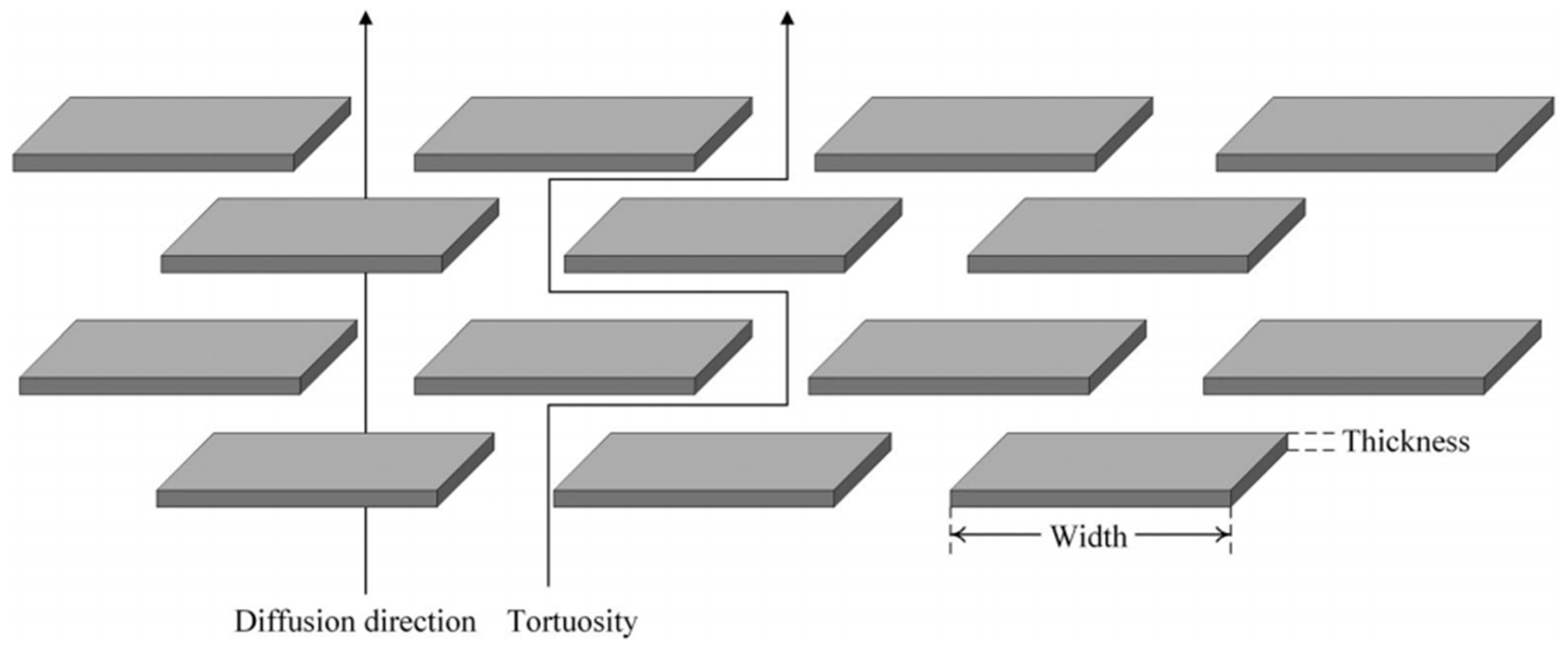
2. Hydrogen Permeation Mechanism in Polymer Liner Materials

Hydrogen embrittlement may occur when the metal liner materials of type II and type III hydrogen storage cylinders come into contact with high-pressure hydrogen. Hydrogen atoms permeate into the metal material and combine to form hydrogen molecules [31]. As the partial hydrogen concentration in the metal liner saturates, the mechanical properties and plasticity of the metal liner decrease, leading to the potential development of cracks or delayed fracture [32,33]. On the other hand, type IV hydrogen storage cylinders use polymer materials to achieve high hydrogen storage densities. Research conducted by the Sandia National Laboratory in the US [34] demonstrates that polymers do not suffer from hydrogen embrittlement as metals do in high-pressure hydrogen environments. This is because the hydrogen absorbed by polymers exists in the form of diatomic molecules and does not segregate, unlike in metals. However, it is worth noting that HDPE and PA, which are commonly used as liner materials in type IV cylinders, are semi-crystalline thermoplastics. Hydrogen molecules permeate slowly through the amorphous zones in their polymeric molecular structures [35,36]. Gas molecule transport in such polymers occurs via a dissolution–diffusion mechanism [37,38]. These differences in hydrogen permeation mechanisms highlight the varying behaviors of metal and polymer materials in hydrogen-rich environments. The gas transport theory proposed by Calvert [39] and Klopffer M.H. [38] assumes that when the polymer comprises a homogeneous, non-porous film at a given temperature, the diffusion process of gas in the polymer can be divided into five steps, as shown in Figure 2.
During the first stage, gas molecules diffuse through the limit layer on the upstream side of the material. In the second stage, these gas molecules are adsorbed by the polymer due to chemical affinity or solubility at the upstream interface. The third stage involves the gas molecules diffusing inside the polymer. During the fourth stage, the gas molecules are received on the downstream side. In the fifth stage, the gas molecules diffuse through the limit layer on the downstream side. The gas barrier properties of the first and fifth stages can be neglected due to the low gas-permeation barrier properties of the limit layer in these referenced stages. The formation of such limit layers is difficult to observe [35]. Therefore, the gas permeation process can be divided into two parts: dissolution and diffusion. Dissolution is a thermodynamic process that depends on the interactions between a gas and a polymer, as well as the compressibility of the gas [40,41]. When hydrogen dissolves in a polymer, it has a plasticizing effect, reducing the material’s strength and increasing its toughness [36]. On the other hand, diffusion is a kinetic term that reflects the mobility of gas molecules in a polymer due to random motion. Permeation is evaluated using two thermodynamic parameters, the diffusion coefficient (D) and the solubility coefficient (S) [42]. The diffusion coefficient (D) describes the permeability of the gas in the polymers, while the solubility coefficient (S) describes the amount of gas contained in the polymer [43].
The steady-state process of gas diffusion in a polymer conforms to Fick’s first law:
J = D c x
where J denotes the gas diffusion flux (mol/m2·s); D is the diffusion coefficient (m2/s); c is the molarity of hydrogen (mol/m3), and x represents the diffusion direction.
The solubility of hydrogen in a polymer conforms to Henry’s law. The hydrogen molecule concentration is proportional to the partial pressure of hydrogen [19,36], as shown in Equation (2):
c = S p H
where S denotes the solubility coefficient (mol/m3·Pa), and pH is the partial pressure of hydrogen (Pa). The hydrogen permeability coefficient of a polymer is the product of the diffusion and solubility coefficients and is expressed as Pe = D × S [44,45].
When hydrogen permeates a polymer of a constant thickness (t = x1x2) from the upstream side and forms a pressure difference in ΔtH on the downstream side, the hydrogen permeation flux J can be expressed as shown in Equation (3):
J = D S ( p H 2 p H 1 ) ( x 1 x 2 ) = D S Δ p H t = P e Δ p H t
The diffusion coefficient D can be obtained from the lag time τ via extrapolation from the linear portion, in which the hydrogen transfer rate reaches a steady state, to the time axis in the integrated transmission curve [46], as shown in Equation (4):
D = l 2 6 τ
where l is the sample thickness (m), and τ is the lag time (s).
For a circular specimen with a thickness of t (m) and a hydrogen-exposed area of A (m2), the steady-state gas permeation rate Fg (mol/s) [47] is shown in Equation (5):
F g = J A
Inserting Formula (5) into Formula (3) allows the permeability coefficient Pe to be calculated as shown in Formula (6):
P e = F g t Δ p H A
The standard unit of the hydrogen permeability coefficient Pe of a polymer is mol·m/(m2·s·Pa). The hydrogen permeation coefficient of a polymer can be calculated as the product of the molar mass of the permeating hydrogen gas at permeation equilibrium and the sample thickness, divided by the hydrogen-exposed area of the sample, the pressure difference across the sample, and the time to reach steady-state permeation.
Based on the hydrogen permeation mechanism described above for polymer liner materials, all existing standards adopt the high-pressure hydrogen gas permeation test method to measure the hydrogen permeation coefficient of liner materials. The calculation formula for the hydrogen permeability coefficient in each standard is represented by Formula (6). The differences in hydrogen permeation test requirements among these standards will be compared and analyzed in Section 3.

3. Hydrogen Permeation Test Methods of the Polymer Liner Material

3.1. Sample Preparation

The sample preparation methods required for hydrogen permeation tests CSA ANSI CHMC 2, ISO 11114-5, and T/CATSI 02 007 are shown in Table 1.
As shown in Table 1, different standards have varying requirements for hydrogen permeation samples. CSA ANSI CHMC 2 and ISO 11114-5 specify that samples should be prepared from the polymer liner. If a comparison of hydrogen permeation performance among multiple liner materials is required, samples can be prepared from polymers produced using the same molding process as the final product. However, the above two standards do not specify sampling position requirements. T/CATSI 02 007 stipulates that samples can be prepared from the polymer liner. For seamless liners, the sampling position is located in the middle of the cylinder, while for welded liners, it is located in the middle of the cylinder, away from the welding seam. Regarding the sample source, when samples are prepared from polymers produced using the same molding process as the final product, material grade and heat treatment processes, such as curing, can affect the hydrogen permeability characteristics of the polymer liner material. Additionally, the sample may have defects, such as wrinkles, creases, and gas cavities formed during molding. Differences in the molding processes used with the prepared specimen and the final product can impact the representativeness of test results [43]. Therefore, if the sample is prepared using the same process as the liner product, it is necessary to specify that the process flow and heat treatment method are consistent with that used to make the liner and that the prepared sample should not have manufacturing defects that affect test results.
In terms of sampling position, injection-molded liners with welds may have defects such as wrinkles, creases, and gas cavities near the weld, which can affect the hydrogen permeability at the welding seam of the liner. There is still a lack of systematic research on the hydrogen permeability at the welding seam of the liner material for the type IV on-board hydrogen storage cylinders. Therefore, it is necessary to study the performance at the welding seam to ensure that the plastic liner hydrogen permeation test considers the area with the weakest hydrogen permeability.
Regarding the sample diameter, CSA ANSI CHMC 2 stipulates that, in order to ensure the consistency of hydrogen permeation test results from the same materials and the comparability of the permeability of different liner materials, the sample diameter should be greater than or equal to 25 mm. A sample diameter of 78 ± 1 mm is recommended, as it matches that of the test device described in the standard. ISO 11114-5 specifies that the sample diameter should be between 40 mm and 80 mm, while T/CATSI 02 007 requires a sample diameter of 78 ± 1 mm. Since the hydrogen permeation sample is sealed in the test device using sealing rings and the support fixture, the sample diameter only needs to exceed the hydrogen leakage area diameter. The sample volume outside the sealing rings should be as small as possible to prevent hydrogen from escaping. Therefore, the sample diameter only needs to exceed that of the hydrogen exposure area of the test device. To ensure the consistency of experimental parameters, a fixed recommended sample diameter can be specified in the standard.
CSA ANSI CHMC 2 requires a sample thickness between 1 mm and 6 mm, with a preference for a sample with the same thickness as the liner. On the other hand, both ISO 11114-5 and T/CATSI 02 007 stipulate that the sample thickness should equal the liner thickness. It is important to avoid machining the sample to change its thickness, as this may create new defects on its surface, thus affecting the hydrogen permeation test results. Therefore, when conducting a hydrogen permeation test for a specific liner material, it is recommended to select the liner thickness as the sample thickness. Furthermore, Fujiwara [41] studied the relationship between the thicknesses of different samples and the diffusion coefficient delay time and verified a linear relationship between the square of the sample thickness and the delay time. This relationship conforms to Formula (4) of the diffusion coefficient. However, since the hydrogen permeability coefficient is determined by both the diffusion and solubility coefficients, whether the sample thickness has a linear relationship with the hydrogen permeability coefficient requires further verification through experimental research.
In summary, the hydrogen permeation test should consider the influence of the molding process and weld defects of the liner material and determine appropriate sample preparation requirements and sampling position. When discussing the specific reasons in depth, they may be closely related to polymer material properties such as molecular chains, crystallinity, and additives. The influence of polymer material properties on the hydrogen permeability of the liner material is discussed in Section 4.3.

3.2. Sample Pretreatment

The sample pretreatment requirements for CSA ANSI CHMC 2, ISO 11114-5, and T/CATSI 02 007 are shown in Table 2.
As shown in Table 2, each standard requires heated drying and vacuum degassing of samples before hydrogen permeation testing. ISO 11114-5 recommends a vacuum pressure of 10–50 mbar, whereas CSA ANSI CHMC 2 and T/CATSI 02 007 do not specify the vacuum pressure. Regarding finishing conditions, CSA ANSI CHMC 2 requires that the mass loss rate within 48 h or 1 h of drying is <0.5%, and ISO 11114-5 requires a mass loss rate within 24 h of drying of <0.1%. It is worth noting that volatile organic compounds (VOCs) from polymer exhaust can affect hydrogen compatibility evaluation test results [22]. Therefore, it is suggested that the liner hydrogen permeation test specifications clarify the required vacuum pressure and specify the mass loss rate of the sample at the end of vacuum drying to ensure that the polymer sample completes the exhaust process.
Regarding the drying temperature, CSA ANSI CHMC 2 recommends a drying temperature of 60 °C; ISO 11114-5 recommends 65 °C, and T/CATSI 02 007 does not give a specific temperature. A study by Emanuele Parodi et al. [48] revealed that PA6, an adipose polyamide consisting of amide and carbonyl groups, exhibited strong hygroscopicity due to its polar character. When exposed to a humid environment, PA6 absorbs water up to a saturation level, resulting in the breaking of hydrogen bonds between the chains and the formation of new hydrogen bonds with the absorbed water molecules. This phenomenon leads to plasticization and depression of the glass transition temperature, resulting in considerable degradation of the mechanical properties. Figure 3 shows the X-ray diffraction (XRD) results and crystalline fractions of PA6 at different relative humidity. As illustrated, the higher the relative humidity, the lower the glass transition temperature of PA6. Under certain conditions, PA6 may experience hydration-induced crystallization at room temperature, increasing its crystallinity and reducing its gas permeability.
Currently, there are numerous studies on the effect of humidity on the crystal structure and mechanical properties of polymer materials, but there is limited research and test data on the hydrogen permeability of liner materials for on-board hydrogen storage cylinders under varying humidity conditions. If the actual working conditions of the liner material are not considered, the sample should be dried during the hydrogen permeability test. It is recommended to keep the drying temperature below the softening temperature of the liner material to prevent softening from affecting test result consistency. However, since on-board hydrogen storage cylinders may operate in high-temperature, high-pressure, and high-humidity environments, it is essential to study the comprehensive influence of humidity, coupled with hydrogen temperature and pressure, on the hydrogen permeability of the liner material to ensure that the hydrogen permeation performance of the liner material meets applicable requirements under high-humidity conditions.

3.3. Test Device

The test devices used in CSA ANSI CHMC 2, ISO 11114-5, and T/CATSI 02 007 are shown in Table 3.
As shown in Table 3, the hydrogen permeation device structures described in the CSA ANSI CHMC 2 and ISO 11114-5 standards are nearly identical, but T/CATSI 02 007 does not specify a test device. Each standard uses the HPHP test method. The test device in the CSA ANSI CHMC 2 and ISO 11114-5 standards mainly consists of a high-pressure sealing cavity, a low-pressure sealing cavity, sealing rings, a wire mesh, and a sintered metal plate. The high-pressure and low-pressure sealed chambers are used to hold samples, while sintered metal plates support wafer specimens to prevent the sample from being squeezed and deformed under high-pressure gas. The wire mesh is placed between the sample and the sintered metal plate to avoid direct contact between the sintered metal and the sample surface and to ensure that hydrogen permeating from the sintered metal is distributed evenly in the exposed area of the sample.
The HPHP method is based on the differential pressure method proposed by Barrier and Brubaker et al. [49,50,51], optimized and improved by integrating the ASTM 1434 and ISO 7229 standards, which were used to measure gas permeation properties at equilibrium. In this method, the sample is placed between the high- and low-pressure chambers, and the gas permeability coefficient is determined by measuring the amount of gas that permeates to the low-pressure chamber. Yamabe et al. [52] also proposed a thermal desorption analysis (TDA) method for measuring the hydrogen permeability coefficient. The sample was exposed to high-pressure hydrogen, and then the emission (elimination) of hydrogen from the polymer material was measured using a gas chromatograph in a non-equilibrium state. The gas permeability and diffusion coefficients were calculated by function fitting. Fujiwara [53] compared hydrogen permeability data of different polymer materials measured by the TDA and HPHP methods. As shown in Figure 4, the permeability coefficients measured by the TDA method were greater than those measured by the HPHP method regardless of the material considered, and the difference between the results increased with the test pressure. The HPHP method can measure the true extent of hydrogen permeation in the high-pressure equilibrium state, and the data are more accurate and more suitable for measuring the hydrogen permeation characteristics of high-pressure hydrogen storage cylinder liner materials [54]. However, the conditions required for continuous data acquisition and pressure maintenance under high-pressure conditions are relatively harsh, the test device is relatively complex, and the test duration is longer.
Regarding the sintered metal plate porosity, CSA ANSI CHMC 2 stipulates that the sintered metal should have a porosity of Grade 2 to ensure that the gas transmission rate of the plate is at least 100 times greater than that of the liner specimen, preventing the gas barrier properties of the sintered metal from affecting test results. Both CSA ANSI CHMC 2 and ISO 11114-5 recommend placing a 140 μm and 150 μm wire mesh, respectively, between the polymer specimen and the porous plate. Since the gas transmission rate of the wire mesh is significantly higher than that of the polymers, the mesh size has no effect on the hydrogen permeation test results [55]. Regarding the hydrogen leakage zone diameter, CSA ANSI CHMC 2 and T/CATSI 02 007 stipulate that it should be greater than or equal to 25 mm, while ISO 11114-5 requires it to be greater than or equal to 30 mm. Theoretically, the amount of hydrogen permeation is proportional to the hydrogen exposure zone diameter, and different hydrogen permeation areas should not affect the hydrogen permeation coefficient. However, some studies have shown that the measured gas permeability coefficient of a sample may appear high when the hydrogen permeation area is small. This could be due to non-isotropic hydrogen diffusion in the thickness direction of the liner [46]. Therefore, further research is needed to understand the influence of the hydrogen exposure zone diameter on hydrogen permeability to determine the appropriate diameter range.
In summary, the three standards define test devices with similar principles and structures, and all use the HPHP method. However, this method requires a higher sealing effect for the O rings. The effect of the O ring hydrogen permeability coefficient cannot be accurately judged due to the existing test device being sealed via sealing rings. Additionally, since the sample diameter is larger than that of the sealing rings, hydrogen may escape from the sample edge. Hence, it is necessary to optimize the structure of the existing test device to improve hydrogen permeation test accuracy.

3.4. Test Temperature and Pressure

The CSA ANSI CHMC 2, ISO 11114-5, and T/CATSI 02 007 temperatures and pressures are shown in Table 4.
As shown in Table 4, ISO11114-5 stipulates that the hydrogen permeation test should be carried out at a certain pressure and temperature, but these values are not specified. However, the test temperature and pressure specifications differ for the other two standards. CSA ANSI CHMC 2 requires the sample to undergo a permeation test at pressures of 0.1 NWP and 1.25 NWP, as well as at test temperatures of 85 °C and 15 ± 5 °C. T/CATSI 02 007 specifies permeation tests at pressures of 0.1 MPa and 1.15 NWP, and at maximum ambient temperatures of 55 ± 1 °C and 15 ± 5 °C.
The choice of test temperature should align with the working conditions and service environment. A maximum allowable temperature of 85 °C is reached temporarily during the filling of on-board hydrogen storage cylinders. Since hydrogen refueling stations are open spaces where hydrogen does not accumulate easily, temperatures above 50 °C can persist for weeks in desert areas [55]. However, in confined spaces such as garages, where hydrogen fuel cell vehicles may be parked for extended periods, hydrogen permeation into the space can cause hydrogen accumulation, leading to potential hazards. Therefore, a high-temperature hydrogen permeation test temperature of 55 °C seems reasonable.
Hydrogen storage systems utilize the SAEJ 2601 filling protocol, where the maximum filling density (100% SOC) of the on-board hydrogen storage system is achieved at a hydrogen temperature of 85 °C and a filling pressure of 1.25 NWP. Conversely, the filling pressure required to reach 100% SOC is NWP at 15 °C and 1.15 NWP at 55 °C [56]. Therefore, a high-temperature, high-pressure hydrogen permeation test conducted at 55 °C and 1.15 NWP is more representative of actual working conditions. CSA ANSI CHMC 2 specifies a pressure of 1.25 NWP for normal-temperature, high-pressure hydrogen permeation tests. Considering that cylinders are used in a normal-temperature environment where gas pressure does not exceed the nominal working pressure, it is more reasonable to perform these tests at 15 °C and the nominal working pressure. Additionally, gas cylinders may be in a no-load state with a slight positive pressure for extended periods. Therefore, it is more reasonable to perform normal-temperature, high-pressure hydrogen permeation tests at 15 °C and the nominal working pressure. In addition, since the gas cylinder may be in a no-load state with a slight positive pressure for a long time, it is more reasonable to use a no-load pressure of 0.1 MPa during a hydrogen permeation test in order to verify the hydrogen permeability of the liner material in a no-load state.
In summary, none of the standards consider the hydrogen permeability of the polymer liner material in a low-temperature environment, and whether the combination of test pressure and test temperature is reasonable remains to be studied. The influence of temperature and pressure on the hydrogen permeability of the liner material is discussed in Section 4.1 and Section 4.2.

3.5. Qualification Indicators

The CSA ANSI CHMC 2, ISO 11114-5, and T/CATSI 02 007 standard hydrogen permeation test qualification indicators are shown in Table 5.
As shown in Table 5, the ISO 11114-5 standard does not specify hydrogen permeation test qualification indicators. However, for type-IV hydrogen storage cylinders, the steady-state hydrogen permeability rate should meet certain criteria. It should be less than 46 NmL/(h·L) at 1.15 NWP and 55 °C and less than 6 NmL/(h·L) at NWP and 15 °C [21,55,57]. T/CATSI 02 007 assigns a maximum allowable hydrogen permeability coefficient value range to each gas cylinder volume range. The hydrogen permeability coefficient of the polymer liner material should not exceed 2 × 10⁻¹³ cm3·cm/(cm2·s·Pa) at 15 °C or 1 × 10⁻¹² cm3·cm/(cm2·s·Pa) at 55 °C. Based on a requirement of 6 NmL/(h·L) for a 60 L cylinder, the CSA ANSI CHMC 2 standard uses a different approach by stipulating that the steady-state gas transmission rate measured at 15 °C for a sample with a diameter of 78 mm be divided into six rating values. Grade 0 indicates the material with the worst hydrogen barrier properties, and grade 10 represents the material with the best hydrogen barrier properties. This quantitative classification of the hydrogen transmission rate provides a standardized system for comparing the hydrogen permeation performances of different materials. Based on specific hydrogen system application scenarios, the minimum acceptable hydrogen permeation test rating value can be specified, providing a clear range of hydrogen permeability coefficient values. This allows for a more accurate evaluation of material suitability for hydrogen storage applications.
In summary, the quantitative classification of the hydrogen transmission rate provides a valuable means to compare the hydrogen permeation performances of various polymer materials. The minimum acceptable hydrogen permeation test rating value can be adjusted based on the specific requirements of different compressed hydrogen systems. However, when using the hydrogen permeation test method to assess whether a chosen liner material possesses good hydrogen permeation resistance, it is advisable to establish a maximum allowable hydrogen permeability coefficient range for the liner material. This can be determined by considering the hydrogen permeation test indicators of gas cylinders and the volume range of gas cylinders. Setting such limits ensures that the selected liner material meets the necessary hydrogen barrier properties for practical applications in different gas storage systems.

4. Discussion

The influence of test temperature, test pressure, and polymer material properties on the hydrogen permeability of the liner material is discussed in this section.

4.1. Test Temperature
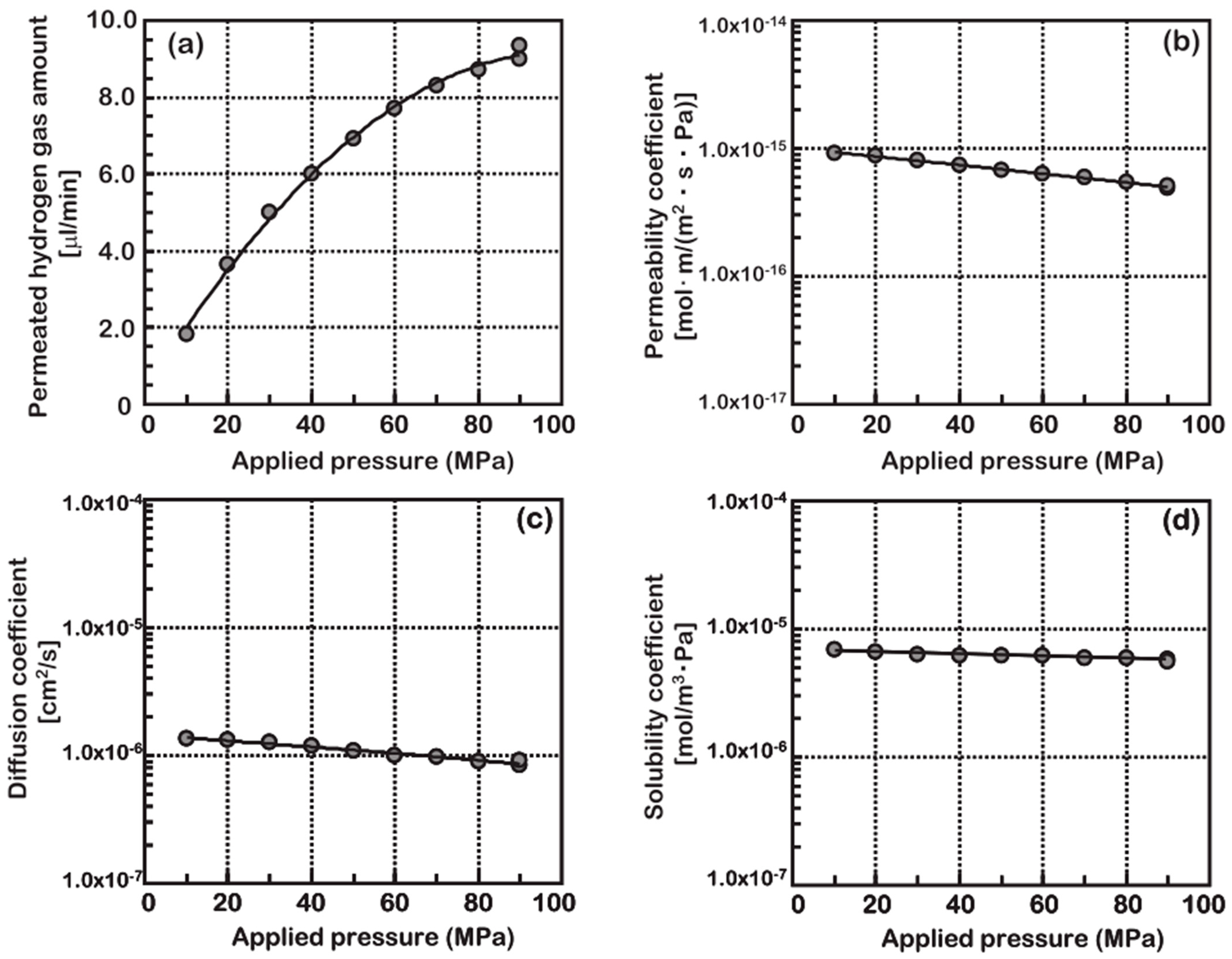
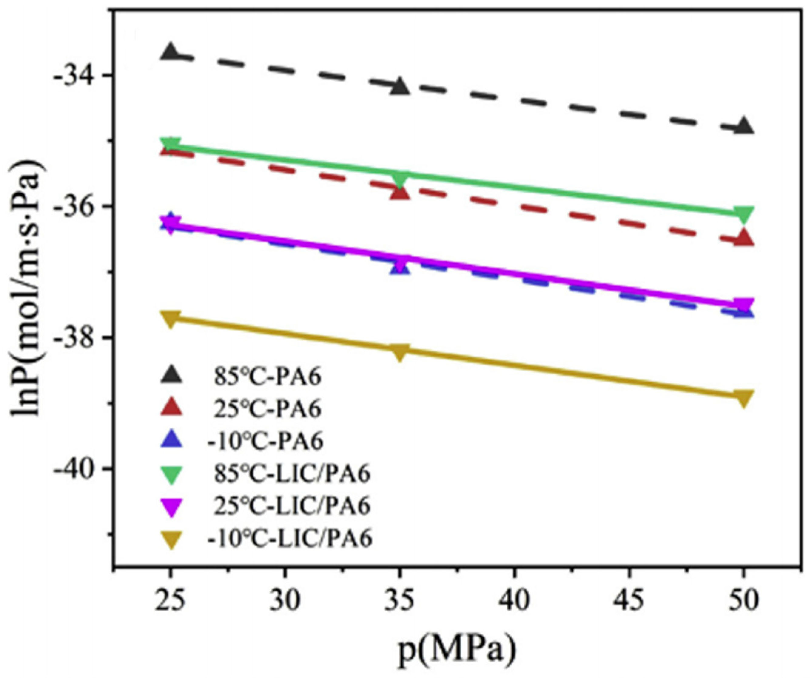
According to the GTR 13 and ISO 19881 standards, the hydrogen temperature in the on-board hydrogen storage system cannot exceed 85 °C during filling at the highest filling pressure [57,58]. The hydrogen must be pre-cooled to −40 °C before filling to avoid over-temperature during the filling process [56]. Therefore, the working temperature range of a hydrogen storage cylinder is −40 °C to 85 °C, and the influence of temperature change on the hydrogen permeability of the polymer liner material is an important research question.
Early theoretical studies [59,60,61] showed that the effects of the temperature on the polymer permeability, diffusion, and solubility coefficients conform to Arrhenius’ law within a certain temperature range:
P e ( T ) = P e 0 exp ( E p R T )
D ( T ) = D 0 exp ( E D R T )
S ( T ) = S 0 exp ( Δ H s R T )
where Pe0, D0, and S0 represent the limit values of various transportation coefficients when the temperature tends to infinity. EP, ED, and ΔHS, respectively, represent the apparent activation energies of the permeation and diffusion processes, and the heat of dissolution required for the penetrant to dissolve in the polymer matrix. The relationship between EP = ΔHS × ED. shows that for hydrogen, both ΔHS and ED are positive [41]. Therefore, at a given pressure, the hydrogen permeation coefficient of the material increases as the temperature increases.
PA6 and HDPE are the most common type-IV on-board hydrogen storage cylinder liner materials [62,63]. Barth et al. [34] analyzed the temperature dependence of hydrogen permeability of several polymer materials (such as HDPE, PA, PVC, butyl rubber, etc.). The permeation of hydrogen in polymer materials at different temperatures is shown in Figure 5. The hydrogen permeability coefficient of all materials increases with the temperature rising. The hydrogen permeation at a temperature of 85 °C will be an order of magnitude greater than at room temperature. Relative reductions in permeation at a low temperature are somewhat greater: at −40 °C, permeation is about 2% of the value at room temperature.
Yu Sun [41] tested the hydrogen permeability of PA6 and LIC/PA6 materials at different temperatures (−10 °C, 25 °C, 85 °C) and different pressures (25–50 MPa). The relationship between the hydrogen permeability coefficient and the temperature of the two materials is shown in Figure 6. The logarithm of the permeability coefficient has a linear relationship with the reciprocal of temperature, indicating that the hydrogen permeability coefficient follows Arrhenius’ law with the change in temperature. Zhang and Rogers et al. [36,61] conducted experimental research on the influence of temperature on the hydrogen permeation performance of HDPE and reached the same conclusion.
The hydrogen permeability coefficient of the material increases with the increase in temperature. This is because the rate of gas penetration is closely related to the motion state of the polymer. The free volume of the polymer and the segmental flow of the polymer determine the hydrogen permeability through the polymer. The temperature rise increases the kinetic energy of the polymer chain and activates the volume expansion, resulting in a larger free space for the moving elements to move. When the temperature gradually rises, the chain segments are unlocked from the frozen state, and mutual movement between side groups, branch chains, or links begins to occur, thereby making it easier for hydrogen molecules to penetrate the polymer [41].
In summary, existing research results indicate that the temperature-dependent hydrogen transport characteristics have mainly been studied at elevated temperatures, with limited data available over a broader temperature range, particularly for polymers in the −40 to 85 °C range. As described in Section 3.4, the current standards only require hydrogen permeation tests at normal and high temperatures, and they do not address hydrogen permeation in the low-temperature environment of −40 °C. Extremely low temperatures can increase material brittleness and reduce mechanical properties [64]. Additionally, micro-cracks in the material may more easily expand under the combined action of low temperature and fatigue load [65], leading to increased hydrogen permeability and the risk of low-temperature failure in severe cases [66,67]. Therefore, it is necessary to perform experimental research on the hydrogen permeation performance characteristics of polymer liner materials in the low-temperature environment of −40 °C and explore whether the hydrogen permeation law that governs liner materials under low-temperature conditions is the same as the general law that governs gas permeability for existing polymer materials.

4.2. Test Pressure

In early studies on gas permeability in pressurized environments, Henry et al. [68] analyzed the permeability of inorganic and organic gases in PEs and PPs pipeline materials at pressurization conditions of up to 1.4 MPa. The results showed that the logarithm of the permeability coefficient was linear with the pressure, and the relationship of pressure to permeability rate varied with the gas species. Li [69] also reached the same conclusion at 10 MPa, where Henry’s law was applicable to the permeability coefficient below the critical pressure, but significant deviations occurred above the critical pressure. Stern [70] studied the influence of gas pressure on permeability for inorganic gases (hydroolefins and fluoroolefin-based organic gases) up to 5.5 MPa in semi-crystalline polymers and discussed the relationship between the permeability process and free volume. The change in the permeability coefficient with pressure was attributed to the correlation effect between the increase in free volume caused by osmotic absorption and the decrease in free volume caused by hydrostatic compression. Naito et al. [60] measured the permeability coefficients of LDPE and PP for several gases at a pressure of 8 MPa, and they found that the hydrogen permeability remained almost unchanged. They considered the effects of gas molecule size and solubility on diffusion, separating the pressure dependence of permeability into two factors related to hydrostatic pressure and concentration. However, as described in Section 3.4, the maximum allowable working pressure for 70 MPa type-IV on-board hydrogen storage cylinders is 87.5 MPa, which is nearly 10 times greater than the pressure used in the previous experiments. Therefore, the influence of the high-pressure hydrogen environment on the hydrogen permeability of type IV on-board hydrogen storage cylinders should be considered, including aspects such as material plasticization caused by gas dissolution and the potential impact of crystallinity changes.
In order to study polymer hydrogen permeability under high-pressure conditions, Fujiwara et al. [46] used the HPHP method to analyze the effects of various pressures (10–90 MPa) on the hydrogen permeability of HDPE, as shown in Figure 7. The experimental results showed that the extent of hydrogen permeation increased with pressure, although the rate of increase gradually decreased. Furthermore, the permeability, diffusion, and solubility coefficients all decreased as the pressure increased. The diffusion coefficient decreased more quickly than the solubility coefficient, indicating that at a certain temperature, hydrogen permeation was mainly affected by diffusion rather than solubility. This finding contrasts with the conclusions drawn from experiments at low pressures. Additionally, the gas permeation process under high pressure did not adhere to Henry’s law. Li [69] arrived at the same conclusion. Barth et al. [34] analyzed that the deviation observed under high pressure was due to the hydrostatic effect. The hydrostatic effect reduces the free volume in the polymer, inhibits the diffusion process, and, consequently, reduces the permeability coefficient.
Yu Sun [41] tested the hydrogen permeability of PA6 and LIC/PA6 materials at different pressures (25 MPa, 35 MPa, 50 MPa). The relationship between the hydrogen permeability coefficient and pressure of the two materials is shown in Figure 8. It can be observed that as the pressure increased, the hydrogen permeability coefficient decreased. This phenomenon is attributed to the type of gas molecule involved in the process. For organic vapor and soluble gases such as CO2, the permeability coefficient tends to increase as pressure rises, whereas, for sparingly soluble gases such as helium and hydrogen, the permeability coefficient decreases with increasing pressure. This occurs because higher pressures cause the polymer to become compacted, leading to increased density, reduced free volume inside the material, and hindered hydrogen diffusion within it [71,72]. Moreover, Fumitoshi et al. [73] found that the crystallinity of polyethylene increases under a high-pressure hydrogen environment, further impeding hydrogen diffusion. However, this change in crystallinity is reversible, with the polymer’s crystallinity returning to its original value when the pressure returns to atmospheric levels.
As described in Section 3.4, the hydrogen permeation test pressure should be determined in combination with the test temperature and actual on-board hydrogen storage cylinder working conditions. The normal working pressure in the type IV hydrogen storage cylinder is as high as 87.5 MPa. Most of the existing experimental studies are carried out under low pressure, and the experimental data on the hydrogen permeability of polymer materials under high pressure are insufficient. Therefore, further research is needed to better understand the laws governing the hydrogen permeability of polymer liner materials under both high and low-pressure conditions.
Additionally, it is important to consider the operating temperature range of type IV hydrogen storage cylinders, which typically spans from −40 °C to 85 °C, and the working pressure range of 0.1 MPa to 1.25 NWP. These cylinders are subject to alternating pressure loads and continuous temperature changes during service, which can potentially affect the hydrogen permeability of the polymer liner material. In extreme temperature conditions, the liner may be at risk of damage, such as blistering and collapse [18], necessitating higher requirements for the hydrogen permeability resistance of liner materials. Therefore, the effect of alternating pressure load (repeated charging and discharging or rapid pressure relief) and temperature change in the hydrogen permeability characteristics of the polymer liner material of type IV on-board hydrogen storage cylinder are also the issues to be further studied in the future.

4.3. Polymer Material Properties

As described in Section 3.1, the influence of the molding process and weld defects of test samples on the hydrogen permeation test is related to polymer structure and properties. This section discussed the effect of material properties on hydrogen permeability, such as crystallinity, molecular chain, and additives.
In order to understand the hydrogen permeability mechanism, Kotono Takeuchi et al. [30] measured the gas permeability of different equivalent weight (EW) perfluorosulfonic acid (PFSA) membranes. For the high-EW (EW > 909) membranes, higher crystallinity decreased the void fraction in the structure and inhibits the hydrogen diffusion across the aligned polymer chains. This effectively reduced hydrogen solubility and diffusivity, thereby reducing hydrogen permeability. Yersak et al. [19] found that although the crystallinity of polyamide was generally lower than polyethylene, the hydrogen penetration rate of polyamide was lower than that of polyethylene. This indicated that there are many factors affecting the hydrogen permeability of polymer materials, which may also be related to the activation energy density in the amorphous region of polymer materials. Hydrogen bonds can be formed in polyamide, which enhances the interaction between molecular chains and reduces permeability. Pepin et al. [74] found that the hydrogen permeability coefficient of PA12 was five times that of PA6 due to the fact that the hydrogen bond density in PA12 was twice that of PA6. Moreover, the side chain groups of the molecular chain in the polymer and the orientation of the molecular chain also influence the gas permeability to a certain extent. The former affects the movement of molecular chains in the polymer, while the latter is related to the way the polymer is formed [40].
The molding process of polymer materials has some influence on hydrogen permeability. Barton Smith [75] tested the hydrogen permeability coefficient of polymer materials such as HDPE, PA, polyethylene terephthalate (PET), and thermotropic liquid crystal polymer (TLCP), and the test results are shown in Table 6. The result showed that there were no statistically significant differences between the permeability of HDPE produced by extrusion molding, rotational molding, and injection molding manufacturing processes. The permeability of PET was about an order of magnitude less than that of HDPE. The permeability of TLCP is comparable to that of blow-molded PET. Moreover, Condé-Wolter et al. [76] found that there were micro-cracks and other defects in the weld of the liner material, which would affect the mechanical properties and increase the hydrogen permeability coefficient of the liner.
In order to improve the hydrogen barrier properties of the liner, fillers can be added to the polymer. Fillers will form a physical barrier in the polymer, making the hydrogen transport path complicated and increasing the tortuous path of the penetrating molecule into the polymer matrix, as shown in Figure 9. Yu Sun [41] found that after PA6 was added with fillers, the cross path of permeating molecules was increased, thus reducing the rate of hydrogen permeation. In addition, the introduction of filler also increased the stiffness of the material, and the flexibility of the polymer chain decreased, making it more difficult for hydrogen molecules to penetrate the polymer. Therefore, how to prepare the inner liner material with good hydrogen barrier properties will be the future research direction.

5. Conclusions and Prospects

The type IV hydrogen storage cylinder has become a research hotspot due to its advantages of light-weight, high-hydrogen storage density, and good fatigue performance. However, hydrogen permeation will occur inevitably in the polymer liner. Therefore, it is necessary and challenging to reduce the hydrogen permeation amount of liner materials as much as possible and to accurately measure the hydrogen permeability rate, which will remain the focus of future research. In this paper, the hydrogen permeation mechanism of the liner material is first discussed in detail. Then, the hydrogen permeation test methods defined by various standards are compared and analyzed, and the factors that affect the process of hydrogen permeation are discussed. This can improve the understanding of the hydrogen permeation mechanism and provide references for subsequent researchers and research on the safety of the liner material of type IV on-board hydrogen storage cylinders.
So far, several standards have been promulgated by international organizations to require permeation tests of the liner material of type IV on-board hydrogen storage cylinders. From the perspective of on-board hydrogen storage cylinder safety, there are still many issues that need to be further studied:
(1) The welded liner prepared by injection molding may have defects such as wrinkles, creases, and gas cavities near the weld, which will affect the hydrogen permeability at the welding seam of the liner. In terms of sampling position, injection-molded liners with welds may have defects such as wrinkles, creases, and gas cavities near the weld, which can affect the hydrogen permeability at the welding seam of the liner. Therefore, it is necessary to study the performance at the welding seam to ensure that the plastic liner hydrogen permeation test considers the area with the weakest hydrogen permeability. The hydrogen permeation test should consider the influence of the molding process and weld defects of the liner material and determine appropriate sample preparation requirements and sampling position;
(2) It is recommended to keep the drying temperature below the softening temperature of the liner material to prevent softening from affecting test result consistency. However, since on-board hydrogen storage cylinders may operate in high-temperature, high-pressure, and high-humidity environments, it is essential to study the comprehensive influence of humidity, coupled with hydrogen temperature and pressure, on the hydrogen permeability of the liner material to ensure that the hydrogen permeation performance of the liner material meets applicable requirements under high-humidity conditions;
(3) The CSA ANSI CHMC 2 and ISO 11114-5 standards define test devices with similar principles and structures, and all use the HPHP method. However, this method requires a higher sealing effect for the O rings. The effect of the O ring hydrogen permeability coefficient cannot be accurately judged due to the existing test device being sealed via sealing rings. Additionally, since the sample diameter is larger than that of the sealing rings, hydrogen may escape from the sample edge. Hence, it is necessary to optimize the structure of the existing test device to improve hydrogen permeation test accuracy;
(4) The existing standard requires only that the polymer liner material undergo hydrogen permeation tests at normal and high temperatures. Hydrogen permeation tests in a low-temperature environment of −40 °C are not considered. Under the combined action of low temperature and fatigue load, micro-cracks in the material may expand more easily, leading to a decline in the hydrogen permeability of the material. Low-temperature failure may occur in severe cases. Therefore, it is necessary to perform experimental research on the hydrogen permeation performance characteristics of polymer liner materials in the low-temperature environment of −40 °C and to explore whether the hydrogen permeation law for polymer liner materials under low-temperature conditions is the same as the general law that governs gas permeability among existing polymer materials;
(5) The current standards only require hydrogen permeation tests at normal and high temperatures, and they do not address hydrogen permeation in the low-temperature environment of −40 °C. Micro-cracks in the material may more easily expand under the combined action of low temperature and fatigue load, leading to increased hydrogen permeability and the risk of low-temperature failure in severe cases. The normal working pressure in the type IV hydrogen storage cylinder is as high as 87.5 MPa. Most of the existing experimental studies are carried out under low pressure, and the experimental data on the hydrogen permeability of polymer materials under high pressure are insufficient. Therefore, further research is needed to better understand the laws governing the hydrogen permeability of polymer liner materials under both high and low-pressure conditions.
Hydrogen permeation test methods in existing standards are different in sample preparation, sample pretreatment, test device, test temperature and pressure, and qualification indicators. The existing hydrogen permeation test method needs to be further improved. In addition, the operating temperature range of the type IV hydrogen storage cylinder is between −40 °C and 85 °C, and the working pressure range is between 0.1 MPa and 1.25 NWP. Since the cylinder is often affected by alternating pressure loads and continuous temperature changes during service, which can potentially affect the hydrogen permeability of the polymer liner material. This puts forward higher requirements for the hydrogen permeability resistance of liner materials. Therefore, the effect of alternating pressure load (repeated charging and discharging or rapid pressure relief) and temperature change on the hydrogen permeability characteristics of the polymer liner material of type IV on-board hydrogen storage cylinder are also the issues to be further studied in the future.

Author Contributions

Conceptualization, X.L. and Q.H.; methodology, J.L.; formal analysis, J.L. and Y.L.; investigation, X.L. and J.L.; resources, Q.H.; writing—original draft preparation, X.L. and J.L.; writing—review and editing, Q.H. and Y.L.; supervision, B.Z.; project administration, B.Z. All authors have read and agreed to the published version of the manuscript.

Funding

This research was funded by the National Key Research and Development Program of China, grant number 2019YFB1504805; Science and Technology Program of CSEI, grant number 2022key10; Key Research and Development Program in Hebei Province, grant number 22314401D.

Institutional Review Board Statement

Not applicable.

Informed Consent Statement

Not applicable.

Data Availability Statement

Not applicable.

Conflicts of Interest

The authors declare no conflict of interest.

References

  1. Li, J.; Liu, J.; Zhao, B.; Wang, D.; Guo, S.; Song, J.; Li, X. Research on Temperature Rise of Type IV Composite Hydrogen Storage Cylinders in Hydrogen Fast-Filling Process. Energies 2023, 16, 2918. [Google Scholar] [CrossRef]
  2. Matsuo, Y.; Endo, S.; Nagatomi, Y.; Shibata, Y.; Komiyama, R.; Fujii, Y. A quantitative analysis of Japan’s optimal power generation mix in 2050 and the role of CO2-free hydrogen. Energy 2018, 165, 1200–1219. [Google Scholar] [CrossRef]
  3. Sgobbi, A.; Nijs, W.; De Miglio, R.; Chiodi, A.; Gargiulo, M.; Thiel, C. How far away is hydrogen? Its role in the medium and long-term decarbonisation of the European energy system. Int. J. Hydrogen Energy 2016, 41, 19–35. [Google Scholar] [CrossRef]
  4. Bakker, S.; van Lente, H.; Meeus, M.T. Credible expectations—The US Department of Energy’s Hydrogen Program as enactor and selector of hydrogen technologies. Technol. Forecast. Soc. Change 2012, 79, 1059–1071. [Google Scholar] [CrossRef]
  5. Jain, I. Hydrogen the fuel for 21st century. Int. J. Hydrogen Energy 2009, 34, 7368–7378. [Google Scholar] [CrossRef]
  6. Jingyuan, L.; Qianghua, H. Technology trends of high pressure vehicle fuel tanks and challenges for China. Press. Vessel Technol. 2014, 31, 43–51. [Google Scholar] [CrossRef]
  7. Schurer, A.P.; Mann, M.E.; Hawkins, E.; Tett, S.F.B.; Hegerl, G.C. Importance of the pre-industrial baseline for likelihood of exceeding Paris goals. Nat. Clim. Chang. 2017, 7, 563–567. [Google Scholar] [CrossRef]
  8. Zheng, J.; Liu, Z.; Hua, Z.; Guch, W.G.; Chen, L. Research status-in-situ and key challenges in hydrogen safety. J. Saf. Environ. 2020, 20, 106–115. [Google Scholar] [CrossRef]
  9. Hwang, H.T.; Varma, A. Hydrogen storage for fuel cell vehicles. Curr. Opin. Chem. Eng. 2014, 5, 42–48. [Google Scholar] [CrossRef]
  10. Manoharan, Y.; Hosseini, S.E.; Butler, B.; Alzhahrani, H.; Senior, B.T.F.; Ashuri, T.; Krohn, J. Hydrogen Fuel Cell Vehicles; Current Status and Future Prospect. Appl. Sci. 2019, 9, 2296. [Google Scholar] [CrossRef] [Green Version]
  11. Valencia, L.B.; Blanc-Vannet, P.; Domergue, D.; Heudier, L.; Jamois, D. Thermal History Resulting in the Failure of Lightweight Fully-Wrapped Composite Pressure Vessel for Hydrogen in a Fire Experimental Facility. Fire Technol. 2015, 52, 421–442. [Google Scholar] [CrossRef]
  12. Huang, Q.; Li, X.; Li, J.; Liu, Y.; Li, X.; Zhu, C. Overview of Standards on Pressure Cycling Test for On-Board Composite Hydrogen Storage Cylinders. In Proceedings of the ASME 2022 Pressure Vessels & Piping Conference, Las Vegas, NV, USA, 17–22 July 2022. [Google Scholar] [CrossRef]
  13. Shi, J.; Cheng, B.; Li, J.; Sun, M.; Li, X.; Li, X. Research on Standard Comparison of Hydrogen Cycling Test Method for On-Board Composite Hydrogen Storage Cylinders. In Proceedings of the ASME 2022 Pressure Vessels & Piping Conference, Las Vegas, NV, USA, 17–22 July 2022. [Google Scholar] [CrossRef]
  14. Li, J.; Lv, R.; Gu, C.; Liu, Y.; Li, J.; Li, X. An Ageing Test Standards Analysis on Thermoplastic Liners of Type IV Composite Hydrogen Storage Tanks. Energies 2023, 16, 2818. [Google Scholar] [CrossRef]
  15. Ahluwalia, R.; Hua, T.; Peng, J. On-board and Off-board performance of hydrogen storage options for light-duty vehicles. Int. J. Hydrogen Energy 2012, 37, 2891–2910. [Google Scholar] [CrossRef]
  16. Pépin, J.; Lainé, E.; Grandidier, J.-C.; Benoit, G.; Mellier, D.; Weber, M.; Langlois, C. Replication of liner collapse phenomenon observed in hyperbaric type IV hydrogen storage vessel by explosive decompression experiments. Int. J. Hydrogen Energy 2018, 43, 4671–4680. [Google Scholar] [CrossRef]
  17. Zhang, M.; Lv, H.; Kang, H.; Zhou, W.; Zhang, C. A literature review of failure prediction and analysis methods for composite high-pressure hydrogen storage tanks. Int. J. Hydrogen Energy 2019, 44, 25777–25799. [Google Scholar] [CrossRef]
  18. Castagnet, S.; Grandidier, J.-C.; Comyn, M.; Benoît, G. Hydrogen influence on the tensile properties of mono and multi-layer polymers for gas distribution. Int. J. Hydrogen Energy 2010, 35, 7633–7640. [Google Scholar] [CrossRef]
  19. Yersak, T.A.; Baker, D.R.; Yanagisawa, Y.; Slavik, S.; Immel, R.; Mack-Gardner, A.; Herrmann, M.; Cai, M. Predictive model for depressurization-induced blistering of type IV tank liners for hydrogen storage. Int. J. Hydrogen Energy 2017, 42, 28910–28917. [Google Scholar] [CrossRef]
  20. Adams, P.; Bengaouer, A.; Cariteau, B.; Molkov, V.; Venetsanos, A. Allowable Hydrogen Permeation Rate from Road Vehicle Compressed Gaseous Storage Systems. Int. J. Hydrogen Energy 2011, 35, 2742–2749. [Google Scholar] [CrossRef]
  21. Gupta, S.; Brinster, J.; Studer, E.; Tkatschenko, I. Hydrogen related risks within a private garage: Concentration measurements in a realistic full scale experimental facility. Int. J. Hydrogen Energy 2009, 34, 5902–5911. [Google Scholar] [CrossRef]
  22. ISO 19881-2018; Gaseous Hydrogen—Land Vehicle Fuel Containers. International Organization for Standardization: Geneva, Switzerland, 2018.
  23. CSA/ANSI CHMC 2:2019; Test Methods for Evaluating Material Compatibility in Compressed Hydrogen Applications Polymers. Canadian Standards Association: Toronto, ON, Canada, 2019.
  24. ISO 11114-5: 2022; Gas Cylinders-Compatibility of Cylinder and Valve Materials with Gas Contents-Part 5: Test Methods for Evaluating Plastic Liners. International Organization for Standardization: Geneva, Switzerland, 2022.
  25. T/CATSI 02 007: 2020; Fully-Wrapped Carbon Fiber Reinforced Cylinder with a Plastic Liner for On-Board Storage of Compressed Hydrogen for Land Vehicles. China Association for Technical Supervision Information: Beijing, China, 2020.
  26. Castagnet, S.; Grandidier, J.-C.; Comyn, M.; Benoît, G. Mechanical Testing of Polymers in Pressurized Hydrogen: Tension, Creep and Ductile Fracture. Exp. Mech. 2011, 52, 229–239. [Google Scholar] [CrossRef]
  27. Cui, Y.; Kundalwal, S.; Kumar, S. Gas barrier performance of graphene/polymer nanocomposites. Carbon 2016, 98, 313–333. [Google Scholar] [CrossRef] [Green Version]
  28. Habel, C.; Tsurko, E.S.; Timmins, R.L.; Hutschreuther, J.; Kunz, R.; Schuchardt, D.D.; Rosenfeldt, S.; Altstädt, V.; Breu, J. Lightweight Ultra-High-Barrier Liners for Helium and Hydrogen. ACS Nano 2020, 14, 7018–7024. [Google Scholar] [CrossRef]
  29. Klopffer, M.-H.; Berne, P.; Espuche, E. Development of Innovating Materials for Distributing Mixtures of Hydrogen and Natural Gas. Study of the Barrier Properties and Durability of Polymer Pipes. Oil Gas Sci. Technol. 2014, 70, 305–315. [Google Scholar] [CrossRef] [Green Version]
  30. Takeuchi, K.; Kuo, A.-T.; Hirai, T.; Miyajima, T.; Urata, S.; Terazono, S.; Okazaki, S.; Shinoda, W. Hydrogen Permeation in Hydrated Perfluorosulfonic Acid Polymer Membranes: Effect of Polymer Crystallinity and Equivalent Weight. J. Phys. Chem. C 2019, 123, 20628–20638. [Google Scholar] [CrossRef]
  31. Briottet, L.; Moro, I.; Escot, M.; Furtado, J.; Bortot, P.; Tamponi, G.; Solin, J.; Odemer, G.; Blanc, C.; Andrieu, E. Fatigue crack initiation and growth in a CrMo steel under hydrogen pressure. Int. J. Hydrogen Energy 2015, 40, 17021–17030. [Google Scholar] [CrossRef] [Green Version]
  32. Hua, Z.; Zhang, X.; Zheng, J.; Gu, C.; Cui, T.; Zhao, Y.; Peng, W. Hydrogen-enhanced fatigue life analysis of Cr–Mo steel high-pressure vessels. Int. J. Hydrogen Energy 2017, 42, 12005–12014. [Google Scholar] [CrossRef]
  33. Yamabe, J.; Itoga, H.; Awane, T.; Matsunaga, H.; Hamada, S.; Matsuoka, S. Fatigue-Life and Leak-Before-Break Assessments of Cr-Mo Steel Pressure Vessels with High-Pressure Gaseous Hydrogen. In Proceedings of the ASME 2014 Pressure Vessels and Piping Conference, Anaheim, CA, USA, 20–24 July 2014. [Google Scholar] [CrossRef]
  34. Barth, R.R.; Simmons, K.L.; Marchi, C.W.S. Polymers for Hydrogen Infrastructure and Vehicle Fuel Systems; Sandia National Lab.: Livermore, CA, USA, 2013. [CrossRef] [Green Version]
  35. Balasooriya, W.; Clute, C.; Schrittesser, B.; Pinter, G. A Review on Applicability, Limitations, and Improvements of Polymeric Materials in High-Pressure Hydrogen Gas Atmospheres. Polym. Rev. 2021, 62, 175–209. [Google Scholar] [CrossRef]
  36. Zhang, D.; Li, H.; Qi, D.; Ding, N.; Shao, X.; Wei, B.; Cai, X. Gas Permeation behaviors of high-density polyethylene as a liner material of flexible pipes. Nat. Gas Ind. 2017, 37, 104–109. [Google Scholar] [CrossRef]
  37. Humpenöder, J. Gas permeation of fibre reinforced plastics. Cryogenics 1998, 38, 143–147. [Google Scholar] [CrossRef]
  38. Klopffer, M.H.; Flaconneche, B. Transport Properdines of Gases in Polymers: Bibliographic Review. Oil Gas Sci. Technol. 2001, 56, 223–244. [Google Scholar] [CrossRef]
  39. Neogi, P. Diffusion in Polymers; CRC Press: Boca Raton, FL, USA, 1996; Volume 32, pp. 290–291. [Google Scholar]
  40. Su, Y.; Lv, H.; Zhou, W.; Zhang, C. Review of the Hydrogen Permeability of the Liner Material of Type IV On-Board Hydrogen Storage Tank. World Electr. Veh. J. 2021, 12, 130. [Google Scholar] [CrossRef]
  41. Sun, Y.; Lv, H.; Zhou, W.; Zhang, C. Research on hydrogen permeability of polyamide 6 as the liner material for type Ⅳ hydrogen storage tank. Int. J. Hydrogen Energy 2020, 45, 24980–24990. [Google Scholar] [CrossRef]
  42. Zhihui, G.; Shufeng, G.; Hailong, S. Analysis and research on key technologies of non-metallic liner fully wound gas cylinder. Auto Manuf. Eng. 2022, 1, 21–27. [Google Scholar] [CrossRef]
  43. Wu, L.; Huang, Q.; Shi, F.; Zhang, Z.; Liu, Y. Research process on the inner liner material of carbon fiber fully-reinforced composite tank with plastic liner. New Chem. Mater. 2022, 50, 262–265. [Google Scholar] [CrossRef]
  44. Lee, J.K.; Yao, S.X.; Li, G.; Jun, M.B.G.; Lee, P.C. Measurement Methods for Solubility and Diffusivity of Gases and Supercritical Fluids in Polymers and Its Applications. Polym. Rev. 2017, 57, 695–747. [Google Scholar] [CrossRef]
  45. Macher, J.; Hausberger, A.; Macher, A.E.; Morak, M.; Schrittesser, B. Critical review of models for H2-permeation through polymers with focus on the differential pressure method. Int. J. Hydrogen Energy 2021, 46, 22574–22590. [Google Scholar] [CrossRef]
  46. Fujiwara, H.; Ono, H.; Onoue, K.; Nishimura, S. High-pressure gaseous hydrogen permeation test method -property of polymeric materials for high-pressure hydrogen devices (1). Int. J. Hydrogen Energy 2020, 45, 29082–29094. [Google Scholar] [CrossRef]
  47. Prewitz, M.; Gaber, M.; Müller, R.; Marotztke, C.; Holtappels, K. Polymer coated glass capillaries and structures for high-pressure hydrogen storage: Permeability and hydrogen tightness. Int. J. Hydrogen Energy 2018, 43, 5637–5644. [Google Scholar] [CrossRef]
  48. Parodi, E.; Peters, G.W.M.; Govaert, L.E. Prediction of plasticity-controlled failure in polyamide 6: Influence of temperature and relative humidity. J. Appl. Polym. Sci. 2018, 135, 45942. [Google Scholar] [CrossRef] [Green Version]
  49. Barrer, R.M.; Rideal, E.K. Permeation, diffusion and solution of gases in organic polymers. Trans. Faraday Soc. 1939, 35, 628–643. [Google Scholar] [CrossRef]
  50. Brubaker, D.W.; Kammermeyer, K. Flow of Gases through Plastic Membranes. Ind. Eng. Chem. 1953, 45, 1148–1152. [Google Scholar] [CrossRef]
  51. van Amerongen, G.J. The Permeability of Different Rubbers to Gases and Its Relation to Diffusivity and Solubility. Rubber Chem. Technol. 1947, 20, 494–514. [Google Scholar] [CrossRef]
  52. Yamabe, J.; Nishimura, S. Influence of fillers on hydrogen penetration properties and blister fracture of rubber composites for O-ring exposed to high-pressure hydrogen gas. Int. J. Hydrogen Energy 2009, 34, 1977–1989. [Google Scholar] [CrossRef]
  53. Fujiwara, H.; Ono, H.; Ohyama, K.; Kasai, M.; Kaneko, F.; Nishimura, S. Hydrogen permeation under high pressure conditions and the destruction of exposed polyethylene-property of polymeric materials for high-pressure hydrogen devices (2). Int. J. Hydrogen Energy 2021, 46, 11832–11848. [Google Scholar] [CrossRef]
  54. Stern, S.A.; Fang, S.M.; Jobbins, R.M. Permeation of gases at high pressures. J. Macromol. Sci. Part B 1971, 5, 41–69. [Google Scholar] [CrossRef]
  55. SAE J2579: 2018; Technical Information Report for Fuel Systems in Fuel Cell and Other Hydrogen Vehicles. Society of Automotive Engineers: Warrendale, PA, USA, 2018.
  56. SAE J2601: 2020; Fueling Protocols for Light Duty Gaseous Hydrogen Surface Vehicles. Society of Automotive Engineers: Warrendale, PA, USA, 2020.
  57. HFCV-GTR: 2013; Global Technical Regulation for Hydrogen Fuel Cell Vehicles. United Nations Economic Commission for Europe: Geneva, Switzerland, 2013.
  58. Maus, S.; Hapke, J.; Na Ranong, C.; Wüchner, E.; Friedlmeier, G.; Wenger, D. Filling procedure for vehicles with compressed hydrogen tanks. Int. J. Hydrogen Energy 2008, 33, 4612–4621. [Google Scholar] [CrossRef]
  59. Flaconneche, B.; Martin, J.; Klopffer, M.H. Transport Properties of Gases in Polymers: Experimental Methods. Oil Gas Sci. Technol. 2001, 56, 245–259. [Google Scholar] [CrossRef] [Green Version]
  60. Naito, Y.; Mizoguchi, K.; Terada, K.; Kamiya, Y. The effect of pressure on gas permeation through semicrystalline polymers above the glass transition temperature. J. Polym. Sci. Part B Polym. Phys. 1991, 29, 457–462. [Google Scholar] [CrossRef]
  61. Rogers, C.E. Permeation of Gases and Vapours in Polymers. In Polymer Permeability; Springer: Berlin, Germany, 1985; pp. 11–73. [Google Scholar] [CrossRef]
  62. Eberle, U.; Müller, B.; von Helmolt, R. Fuel cell electric vehicles and hydrogen infrastructure: Status 2012. Energy Environ. Sci. 2012, 5, 8780–8798. [Google Scholar] [CrossRef]
  63. Hua, T.Q.; Ahluwalia, R.K.; Peng, J.-K.; Kromer, M.; Lasher, S.; McKenney, K.; Law, K.; Sinha, J. Technical assessment of compressed hydrogen storage tank systems for automotive applications. Int. J. Hydrogen Energy 2011, 36, 3037–3049. [Google Scholar] [CrossRef] [Green Version]
  64. Flaconneche, B.; Martin, J.; Klopffer, M.H. Permeability, Diffusion and Solubility of Gases in Polyethylene, Polyamide 11 and Poly (Vinylidene Fluoride). Oil Gas Sci. Technol. 2001, 56, 261–278. [Google Scholar] [CrossRef] [Green Version]
  65. Wang, G.; Zhou, J.; Hu, S.; Dong, S.; Wei, P. Investigations of filling mass with the dependence of heat transfer during fast filling of hydrogen cylinders. Int. J. Hydrogen Energy 2014, 39, 4380–4388. [Google Scholar] [CrossRef]
  66. Kumar, S.S.; Kanagaraj, G. Investigation on Mechanical and Tribological Behaviors of PA6 and Graphite-Reinforced PA6 Polymer Composites. Arab. J. Sci. Eng. 2016, 41, 4347–4357. [Google Scholar] [CrossRef]
  67. Vasudeo, R.A.; Vk, A.; Vr, U.; Samarth, N.; Jadhav, S.; Patil, S.; Vr, A.; Narute, S. Development in Air Permeability of Natural Rubber Tire Tube Compound by Adding Variable Dosage of Nanoclay. Macromol. Symp. 2016, 361, 34–41. [Google Scholar] [CrossRef]
  68. Li, N.N.; Henley, E.J. Permeation of gases through polyethylene films at elevated pressures. AIChE J. 1964, 10, 666–670. [Google Scholar] [CrossRef]
  69. Li, N.N.; Long, R.B. Permeation through plastic films. AIChE J. 1969, 15, 73–80. [Google Scholar] [CrossRef]
  70. Stern, S.A.; Mullhaupt, J.T.; Gareis, P.J. The effect of pressure on the permeation of gases and vapors through polyethylene. Usefulness of the corresponding states principle. AIChE J. 1969, 15, 64–73. [Google Scholar] [CrossRef]
  71. Stern, S.A.; Fang, S.-M.; Frisch, H.L. Effect of pressure on gas permeability coefficients. A new application of “free volume” theory. J. Polym. Sci. Part A-2 Polym. Phys. 1972, 10, 201–219. [Google Scholar] [CrossRef]
  72. Naito, Y.; Bourbon, D.; Terada, K.; Kamiya, Y. Permeation of high-pressure gases in poly(ethylene-co-vinyl acetate). J. Polym. Sci. Part B Polym. Phys. 1993, 31, 693–697. [Google Scholar] [CrossRef]
  73. Fumitoshi, K.; Hirotada, F.; Shin, N. Influence of high-pressure hydrogen gas on crystalline polymers. In Proceedings of the 33rd Polymer Degradation Discussion Group, St. Julians, Malta, 1–5 September 2019. [Google Scholar]
  74. Pepin, J.; Lainé, E.; Grandidier, J.-C.; Castagnet, S.; Blanc-Vannet, P.; Papin, P.; Weber, M. Determination of key parameters responsible for polymeric liner collapse in hyperbaric type IV hydrogen storage vessels. Int. J. Hydrogen Energy 2018, 43, 16386–16399. [Google Scholar] [CrossRef]
  75. Smith, B.; Anovitz, L.M. IV.F.1 Lifecycle Verification of Polymeric Storage Liners. Available online: https://www.hydrogen.energy.gov/pdfs/progress13/iv_f_1_smith_2013.pdf (accessed on 14 July 2021).
  76. Condé-Wolter, J.; Ruf, M.G.; Liebsch, A.; Lebelt, T.; Koch, I.; Drechsler, K.; Gude, M. Hydrogen permeability of thermoplastic composites and liner systems for future mobility applications. Compos. Part A Appl. Sci. Manuf. 2023, 167, 107446. [Google Scholar] [CrossRef]
Figure 1. The structure of the type IV hydrogen storage cylinder and polymer liner.
Materials 16 05366 g001
Figure 2. The diffusion process of gas in the polymer, reproduced with permission from [38].
Materials 16 05366 g002
Figure 3. (a) Wide angle X-ray diffraction integrated patterns of samples conditioned at different relative humidity and 23 °C; (b) crystalline fractions as functions of relative humidity, obtained by deconvolution analysis, reproduced with permission from [48].
Materials 16 05366 g003
Figure 4. Correlativity of HPHP and TDA method. (a) Amount of penetrated hydrogen gas. (b) Permeability. Numbers in the plot show the exposed pressure, reproduced with permission from [53].
Materials 16 05366 g004
Figure 5. Temperature dependence of hydrogen permeability of several polymer materials, reproduced with permission from [34].
Materials 16 05366 g005
Figure 6. The relationship between hydrogen permeability coefficient and temperature of PA6 and LIC/PA6, reproduced with permission from [41].
Materials 16 05366 g006
Figure 7. The results of high-pressure permeation tests performed at 30 °C. The influence of the applied pressure on the (a) amount of hydrogen gas that permeates, (b) permeability, (c) diffusion coefficient, and (d) solubility coefficient, reproduced with permission from [46].
Materials 16 05366 g007
Figure 8. The relationship between hydrogen permeability coefficient and pressure of PA6 and LIC/PA6, reproduced with permission from [41].
Materials 16 05366 g008
Figure 9. Increased tortuous path length, generated by orthogonally arranged two-dimensional obstacles, reproduced with permission from [35].
Materials 16 05366 g009
Table 1. Comparison of the sample preparation requirements imposed by various standards.
StandardCSA ANSI CHMC 2ISO 11114-5T/CATSI 02 007
Sample sourceSample from polymer liner or prepared from polymer liner produced using same molding process as the productSame as CSA ANSI CHMC 2Sample from polymer liner
Sampling positionUnspecifiedUnspecifiedSeamless liner: middle of cylinder Welded liner: middle of cylinder away from the welding seam
Diameter (mm)≥25 mm (recommend 78)Between 40 mm and 80 mm78 mm
Thickness (mm)1 ≤ liner thickness ≤ 6 (recommend liner thickness)Liner thicknessLiner thickness
Table 2. Comparison of sample pretreatment requirements imposed by various standards.
StandardCSA ANSI CHMC 2ISO 11114-5T/CATSI 02 007
Drying temperatureRecommend 60 °CRecommend 65 °CUnspecified
Vacuum pressureUnspecifiedRecommend 10–50 mbarUnspecified
Vacuum drying finish conditionsMass loss rate within 48 h or 1 h of drying is <0.5%The mass loss rate within 24 h of drying is <0.1%Unspecified
Table 3. Comparison of the test devices used by the different standards.
StandardCSA ANSI CHMC 2ISO 11114-5T/CATSI 02 007
Device structure diagramMaterials 16 05366 i001Materials 16 05366 i002Unspecified
Test MethodHPHP methodHPHP methodHPHP method
Sintered metal plate porosityPorosity reaches grade 2UnspecifiedUnspecified
Wire mesh size140 μm150 μmUnspecified
Hydrogen exposure zone diameter≥di mm≥di mm≥di mm
Table 4. Comparison of test temperatures and pressures.
StandardCSA ANSI CHMC 2ISO 11114-5T/CATSI 02 007
Test temperature and pressure(85 ± 1) °C, 1.25 NWP,
(15 ± 1) °C, 1.25 NWP,
(85 ± 1) °C, 0.1 NWP,
(15 ± 1) °C, 0.1 NWP.
Test should be carried out at a certain pressure and temperature(55 ± 1) °C, 1.15 NWP,
(15 ± 1) °C, NWP,
(55 ± 1) °C, 0.1 MPa,
(15 ± 1) °C, 0.1 MPa.
Table 5. Comparison of qualification indicators defined by various standards.
StandardCSA ANSI CHMC 2ISO 11114-5T/CATSI 02 007
Qualification indicatorsThe steady-state gas transmission rate measured at 15 °C for a sample with a diameter of 78 mm is divided into six rating values:
10: ≤0.8 Ncm³/h, 8: >0.8–1.5 Ncm³/h, 6: >1.5–3 Ncm³/h, 4: >3–6 Ncm³/h, 2: >6–16 Ncm³/h, and 0: >16 Ncm³/h.
UnspecifiedAt 15 °C, Pe ≤ 1 × 10⁻¹³ cm3·cm/(cm2·s·Pa),
At 55 °C, Pe ≤ 1 × 10⁻¹² cm3·cm/(cm2·s·Pa)
Table 6. Test results of hydrogen permeability coefficient of different polymer materials under different molding processes.
PolymerPressure/BarPe/mol H2·m/(m2·s)
Injection-molded HDPE1342.08 × 10−10
Extrusion-molded HDPE1045.51 × 10−11
Rotomolded HDPE3452.58 × 10−10
Extrusion-molded PA61373.38 × 10−11
Compression-molded TLCP1367.09 × 10−13
Blow-molded PET1376.71 × 10−12
Disclaimer/Publisher’s Note: The statements, opinions and data contained in all publications are solely those of the individual author(s) and contributor(s) and not of MDPI and/or the editor(s). MDPI and/or the editor(s) disclaim responsibility for any injury to people or property resulting from any ideas, methods, instructions or products referred to in the content.

