2. High Cycle Fatigue Resistance
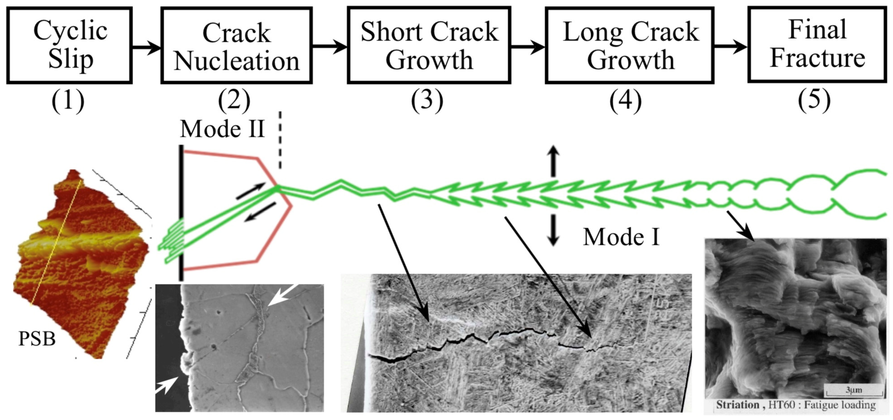
Figure 1 presents a schematic representation of the evolution of a fatigue crack initiated from a polished surface of a defect-free metallic alloy. Additionally, the figure showcases various crack lengths and illustrates the generation of surface damage on carbon steels.
Due to low applied nominal stresses (high cycle fatigue) and surface concentration effects, plastic deformation is confined to specific grains with favorable orientations, minimizing restrictions from neighboring grains. With increasing cycles, damage grows, causing persistent slip bands (PSB) induced by shear stresses, resulting in intrusions and extrusions (stage 1). Localized damage areas lead to microcracks similar in size to the microstructure (e.g.,
Figure 1, mode II crack arrested at a grain boundary, stage 2). Early microcrack propagation culminates in macrocrack formation (stage 3), and subsequent engineering crack propagation leads to final failure or fracture (stages 4 and 5).
Accurately predicting total fatigue life, encompassing both long fatigue crack propagation and short crack regimes, hinges on properly quantifying fatigue crack initiation life (stages 1 and 2). However, in scenarios involving components with small cracks or crack-like defects, such as additive manufactured metals, slip damage localization and microcrack generation stages may be negligible. Consequently, fatigue behavior becomes dominated by the propagation of undetectable microcracks until component failure. To address this, reliable prediction models for non-detectable cracks (short cracks) are essential [
3,
7,
8,
9,
10,
11,
12]. In the subsequent sections, we analyze various aspects of fracture mechanics models utilized for these tasks.
2.1. Crack Initiation and Intrinsic Fatigue Limit
The crack initiation mechanism has been a significant focus of research for decades [
13,
14,
15], with numerous models proposed, primarily based on dislocation movement [
14,
15,
16]. Historically, the interpretation of the fatigue limit as the “limit of crack initiation under cyclic stress” was prevalent [
17,
18,
19] (as it is pointed out by Murakami [
4]). For cases where a fatigue limit cannot be determined, an “endurance limit” for a specific fatigue life (e.g., 10
7 cycles) may be considered instead.
In the present understanding, the high-cycle intrinsic fatigue limit is no longer viewed as a critical stress for crack initiation. Instead, it represents the stress level below which an already initiated micro-crack cannot propagate. In essence, the intrinsic fatigue limit acts as a threshold stress for micro-crack growth. This concept was clearly reported by Miller in reference [
6], employing a Kitagawa–Takahashi diagram [
20], which illustrates the threshold stress range for crack propagation as a function of crack length (see
Figure 2). This limit is material-based and depends on the microstructural characteristic dimension (
d) [
6]. Early evidence supporting this concept can also be found in the thorough analyses of Tanaka et al. [
21] and Tokaji et al. [
22]. Previous research by Kitano, Chapetti, and their colleagues [
23,
24,
25,
26,
27,
28,
29] delved into the position and effective resistance of microstructural barriers, establishing their relation to the fatigue limit. These studies provide additional evidence that the intrinsic fatigue limit for plain and blunt-notched samples is defined by the strongest microstructural barrier. This shift in perspective has brought greater clarity to the fatigue phenomenon, emphasizing the significance of limiting crack growth rather than merely preventing crack initiation. The Kitagawa–Takahashi diagram has become an invaluable tool in fatigue research, aiding in the prediction of crack propagation behavior and enabling more precise and efficient fatigue life assessments in various materials and engineering applications.
In reference [
23,
24], three different steel microstructures were analyzed under tension-compression (
R = −1): ferrite (JIS SS-400, σ
U = 438 MPa, H
V = 127 Kgf/mm
2,
d = 38 μm and Δσ
eR = 420 MPa), ferrite-bainite (JIS SW12-3, σ
U = 552 MPa, H
V = 181 Kgf/mm
2,
d = 50 μm and Δσ
eR = 510 MPa) and bainite-martensite (JIS SW12-5, σ
U = 740 MPa, H
V = 288 Kgf/mm
2,
d = 50 μm and Δσ
eR = 580 MPa). The sample surfaces were totally polished and revealed before testing.
Figure 3 illustrates non-propagating cracks found in samples tested at stress levels at or just below the fatigue limit (run-out results for 10
7 cycles). Some of these cracks are newly published, while others were previously reported in publications [
23,
24,
27,
28]. All non-propagating cracks were effectively arrested by the first and strongest barrier directly associated with the material’s intrinsic fatigue limit. These cracks occur naturally without the introduction of artificial defects to localize their nucleation, as is commonly done. It should be noted that naturally nucleated cracks manifest themselves in the weakest configuration along the entire surface of the sample, making their localization arduous and time-consuming. However, this approach represents the most appropriate method for studying crack nucleation processes in any material. Another crucial aspect to consider is the necessity of observing and analyzing not only the surface path of the crack but also, primarily, its depth and the position of the crack tip in relation to microstructural barriers.
Figure 3 provides surface observations of the non-propagating (or arrested) cracks associated with the intrinsic fatigue limit of the three microstructures. Additionally, cross-section examples of these cracks clearly demonstrate the influence of microstructural barriers that define the intrinsic fatigue limit and allow for their identification. These barriers represent a microstructural threshold for micro-crack growth. Nowadays, advanced equipment such as Scanning Electron Microscopy-Focused Ion Beam (SEM-FIB) is available, making the task of understanding crack nucleation processes much simpler and faster. Therefore, carrying out this task no longer requires significant effort and should be widely adopted when analyzing these topics.
In reference to [
27], Chapetti et al. conducted a comprehensive analysis of the impact of four distinct static strengthening methods on fatigue crack initiation, fatigue limit, and blunt-notch sensitivity in low-carbon steels with a ferrite–pearlite microstructure. The microstructural barriers’ average distance (
d) was kept constant by maintaining a consistent average grain size, while the effective resistance to crack growth was increased using static strengthening. All microstructures exhibited a ferrite
–pearlite configuration with a similar grain size (55 μm). To investigate the intrinsic fatigue limits of each configuration, test specimens were examined at nominal stress levels just below and very close to the experimental intrinsic fatigue limit (similar to the approach used in references [
23,
24]). In all cases, the non-propagating cracks associated with the intrinsic fatigue limit were consistently found to be arrested by the first grain boundary, with a depth equivalent to the average grain size. These findings provided further compelling evidence that, in most instances, the intrinsic fatigue limit is determined using the strongest microstructural barrier, as previously suggested by Miller [
6] (see
Figure 2). The resistance to crack propagation is generally greater than the resistance to crack nucleation, reinforcing the critical role of microstructural barriers in defining the intrinsic fatigue limit of the material.
Based on the experimental evidence, the intrinsic fatigue limit can be precisely defined as the capacity of the strongest microstructural barrier (e.g., grain boundary) to arrest a micro-crack. Utilizing the intrinsic fatigue limit, Δσ
eR, and the average distance from the surface to the strongest microstructural barrier (corresponding to the average microstructural size,
d), a minimum intrinsic resistance to micro-crack growth (microstructural threshold, ΔK
dR) can be established for a given load ratio
R. This formulation was proposed by Chapetti [
8] and is depicted in
Figure 2, as follows:
Y is the geometric correction factor that is taken conservatively as 0.65 because, in most cases, microstructural short cracks nucleated at surfaces are considered semicircular [
23,
24,
30]. The ‘
R’ subscript indicates that as Δσ
eR is
R-ratio (load ratio) dependent, ΔK
dR also is.
The ΔK
dR parameter, a microstructural threshold, represents the minimum driving force we can apply to propagate a crack of size
d. Furthermore, it defines a minimum intrinsic stress range as a function of crack length associated with the total threshold for crack growth, as shown by the red line in
Figure 2.
It is important to mention here that to experimentally analyze this intrinsic microstructural propagation threshold associated with the intrinsic fatigue limit of the material, it is necessary to analyze naturally nucleated cracks. Artificial defects cannot be used because the intrinsic fatigue limit is given by the weakest microstructural configurations in microstructural entities favorably oriented to induce surface strain concentrations. Any artificially introduced defect would neglect this concept and would introduce substantial changes that would make the configuration finally studied different from the one that would naturally be generated when a fatigue crack nucleates.
2.2. The Microstructural Threshold ΔKdR and the Surface Strain Concentration
Once the la crack is nucleated and overcome the barrier associated with the intrinsic fatigue limit, several transition processes take place. These include the effect of surface strain concentration, which involves the first 3 or 4 microstructural entities, the transition of the crack opening mode, shifting from mode II during crack nucleation to opening mode I as the crack propagates and develops further, and the development of the crack closure phenomenon (initially null when the crack nucleates). The analysis of crack closure and its fundamental concepts will not be discussed in detail here, but they can be explored in the extensive available literature [
31,
32,
33,
34,
35,
36]. Additionally, the concepts related to the transition of the propagation mode, which depends on various material properties and its microstructure, will not be covered in this discussion. What is important to highlight is the concept of surface strain concentration since it is generally unknown or dismissed by many analyses that only contemplate the development of crack closure as the only phenomenon associated with the development of the propagation threshold, ΔK
th (see, for instance [
1,
2,
9,
10]). As will be discussed later, this can be the case once the crack has passed 3 or 4 microstructural entities. However, the disregarded phenomenon does not allow extrapolating the effective thresholds of long cracks (ΔK
th,eff) to microcracks associated with the intrinsic fatigue limit of sizes similar to the microstructural size
d.
Figure 4 illustrates the concept proposed by Abdel-Raouf, Topper, and Plumtree [
37,
38], elucidating the inherent surface strain concentration phenomenon. The explanation centers around the disparity in deformation between the material at the free surface and the interior, where neighboring grains provide support (with increasing constraint at depth). Additionally, the free surface of polycrystalline alloys comprises numerous randomly oriented grains, each with different slip system orientations relative to the loading axis. This leads to a strain redistribution process. The strain in the surface is accommodated due to the lack of constraint, and the local strain is proportionate to the corresponding grain orientation. Favorably oriented grains undergo more surface deformation and experience a higher level of localized slip, thus serving as preferred sites for crack initiation.
In contrast, within the material’s interior, grains mutually support each other, leading to a decrease in local strain with depth into the specimen until it approaches the nominal strain range. This results in a constraint gradient, which arises from the variation in grain orientations and the lack of constraint at the surface. As the local strain diminishes with depth, it approaches the nominal strain range due to increased constraint and strain compatibility requirements. Furthermore, they argued that the rate of decay is influenced by the average grain size d, meaning that larger grains exhibit deeper local resolved shear strain (greater deformation) and have less surface area per unit volume of contact with neighboring grains, consequently experiencing less constraint.
After the crack departs from the region influenced by these phenomena, the dominant factor in the development of the crack growth threshold, ΔKth, becomes the crack closure effect, which initiates during the early stages of crack growth.
Those phenomena were considered by Chapetti when proposing his model. The minimum threshold ΔK
dR (see Equation (1)) is defined by the experimentally measured intrinsic fatigue limit, Δσ
eR, which implicitly includes and quantifies all the phenomena mentioned above. Additional work on the estimation of the complementary extension force due to the surface strain concentration is reported in reference [
26].
The concentration of deformations on the surface plays a critical role in defining the intrinsic fatigue limit because it is dependent on the weakest configuration that generates the dominant crack. This further supports the difficulty in extrapolating the effective threshold for long cracks, ΔKth,eff (threshold without crack closure), to determine a non-propagating crack length connected to the intrinsic fatigue limit. The value obtained from this method cannot be linked to the microstructure and does not represent the length physically associated with the intrinsic fatigue limit of the material.
Figure 5 shows the basic differences between models that use the concept of crack closure and the Chapetti model. The underlying assumptions associated with the intrinsic fatigue limit are different. This is important in order to correctly define an intrinsic fatigue limit and the associated variables. While the former assumes that the intrinsic fatigue limit is determined by the effective crack propagation threshold, ΔK
th,eff (thus, the non-propagating crack length
a0,eff associated with the intrinsic fatigue limit increases as the load ratio increases because Δσ
eR decreases), the latter defines the microstructural threshold ΔK
dR considering a fixed non-propagating crack length given by the average microstructural size
d, yielding different values of ΔK
dR for different fatigue limits Δσ
eR (different load ratio
R).
Table 1 presents ΔK
dR and
a0,eff results for values of Δσ
eR, ΔK
th, and
d obtained from the literature for various metals [
21,
27,
29,
39,
40,
41,
42], along with reported or estimated values of the effective threshold using the expression ΔK
th,eff ≈ 1.3 × 10
−5 E [
3,
43], and E = 200 GPa.
It is evident that the crack closure model hypothesis gives rise to non-propagating cracks linked to the intrinsic fatigue limit that can extend up to four times the size of the microstructure. In the case of materials with small grain sizes, this effect can be even more pronounced. For instance, in the case of S20C steel with a diameter of 7.8 μm and a stress ratio R = 0, the estimated non-propagating crack size can reach up to twelve times the microstructural size.
a0,eff is, by definition and as a result of the crack closure model hypothesis, directly independent of
d and is only defined, for a given ΔK
th,eff, by the intrinsic fatigue limit Δσ
eR. However, it is possible to increase the intrinsic fatigue limit without varying the microstructural size
d. This can be observed, for example, in the previously referenced work [
27], where five ferritic steels with similar microstructural sizes (average ferrite grain size
d = 55 μm) but different intrinsic fatigue limits generated using the addition of alloying elements or precipitation heat treatment are analyzed.
If we analyze the case of the high-strength steel JIS SUJ2 [
40],
a0,eff is estimated to be 1 μm, one-tenth of the microstructural size
d (10 μm). This creates a configuration that requires an appropriate phenomenological explanation to be justified, which does not allow the use of the entire microstructural entity to explain crack nucleation.
On the other hand, in the case of ultrafine-grained steel (0.8 μm), the concept of crack closure applied to the intrinsic fatigue limit yields an
a0,eff ten times the microstructural size
d. Experimental evidence shows that it was not possible to find non-propagating cracks larger than
d associated with the intrinsic fatigue limit. This was only possible for fatigue limits with stress concentrators:
anp = 2 μm for
kt = 2, and
anp = 4 μm for
kt = 2.8 (see details in reference [
29]), far from the estimated
a0,eff = 10
d.
This author has not been able to find conclusive experimental evidence in the literature correlating the observed non-propagating crack length at the intrinsic fatigue limit for a given load ratio and the length estimated using the ΔK
th,eff criterion. In fact, this author proposed Equation (1) as a minimum threshold for microcrack growth for the intrinsic fatigue limit as a result of being unable to explain the experimental observations using only the concept of crack closure [
24,
26,
28].
2.3. Fatigue Crack Propagation Threshold Curve: ΔKth vs. a, estimation Models
Let us analyze the transition between the threshold associated with the intrinsic fatigue limit, Δσ
eR (or ΔK
dR, the minimum threshold value), and the threshold for long crack propagation, ΔK
thR (the maximum threshold value). This transition is complex as it involves dealing with very small cracks in threshold configurations within a specific range of crack lengths. The Chapetti model [
8] and the Murakami–Endo model [
7] are used here to analyze the short crack regime. Refer to references [
11,
44] for a detailed analysis of this range of short cracks and a discussion of hypotheses regarding various prediction models for threshold curves and their differences.
Based on the analysis conducted in the previous section, models that rely solely on the concept of crack closure will not be used. Neither is the El Haddad model [
12], as it does not allow for the definition of a minimum threshold value in terms of ΔK
th associated with the intrinsic fatigue limit (in fact, this model indicates ΔK
th = 0 for
a = 0).
2.3.1. The Chapetti Model
In
Section 2.1, Chapetti’s hypothesis was introduced, stating that the minimum ΔK
th associated with the intrinsic fatigue limit is equal to ΔK
dR. It can be estimated using the same intrinsic fatigue limit and the average microstructural size
d (e.g., grain size) as expressed in Equation (1) (refer to
Figure 2). This hypothesis is based on the idea that the intrinsic fatigue limit is determined using the capacity of the strongest microstructural barrier (e.g., grain boundary) to arrest a micro-crack. The parameter ΔK
dR represents the minimum driving force required to propagate a crack of size
d. This value serves as the starting point for the threshold, which then evolves until it reaches its maximum value, defined by the long crack threshold, ΔK
thR.
According to Chapetti’s model, the threshold for crack growth comprises both a “microstructural” component, ΔK
dR, and an “extrinsic” component, which is a function of crack length and is equal to (ΔK
th − ΔK
dR). As the crack length increases, this extrinsic component fully develops and reaches a maximum value (ΔK
thR − ΔK
dR) for long cracks. Chapetti proposed an exponential function to model the development of (ΔK
th − ΔK
dR), leading to the following expression for estimating the threshold for short crack growth as a function of crack length [
8]:
where
a is the crack length and
k is a material constant given by the following expression [
8]:
Equations (2) and (3) are fully defined once Δσ
eR, ΔK
thR, and
d are known. Further details of this model can be found in references [
8,
11].
In Chapetti’s model, the resistance curve ΔK
th vs.
a does not require a “fitting parameter”
k. Equation (3) is derived from hypotheses associated with the proposed model, and factor 4 is the only contribution stemming from both the model’s hypotheses and a fitting procedure applied to various sets of threshold data for short cracks at the time of proposal [
8]. However, when utilizing the model, Equations (2) and (3) do not necessitate any fitting procedure and offer a direct estimation of the threshold curve, providing a reliable and pure prediction of crack growth thresholds.
Equations (2) and (3) are widely employed by various authors to estimate the resistance curve in models considering that the minimum crack propagation threshold, ΔK
th, associated with the intrinsic fatigue limit, is represented by the effective propagation threshold, ΔK
th,eff (crack closure models). This approach yields acceptable results, particularly in analyses where the intrinsic length
a0,eff related to the fatigue limit exhibits dimensions similar to the microstructural size
d, but it cannot be generalized, as this practice can yield considerably different results, as we have seen in
Section 2.2.
For more details on the prediction models that use the crack closure concept, references [
9] and [
10] can be consulted for the proposals of McEvily et al. and Tanaka and Akiniwa, respectively. McEvily’s model is often confused with Chapetti’s model, but they only have in common the exponential mathematical expression to express the development of the propagation threshold since the models are based on substantially different hypotheses. Some studies even use the McEvily model (and its hypotheses) but resort to the parameter
k of the Chapetti model (Equation (3)) to estimate its exponential development parameter (see, for instance, [
45,
46]). These procedures mix hypotheses and run the risk of generating weakly supported conclusions, mainly for alloys with relatively small defects.
2.3.2. The Murakami–Endo Model
The Murakami–Endo model [
7] provides an estimation of the threshold ΔK
th for small cracks and defects by considering the Vickers hardness, H
V, and the
area1/2 parameter, which is the square root of the area resulting from projecting a small defect or crack onto a plane perpendicular to the maximum principal stress. To estimate the threshold stress range Δσ
th for surface cracks with
R = −1 [
4,
7], Murakami and Endo proposed the following expression:
where
area1/2 is in μm and
HV in kgf/mm
2, given Δ
σth in MPa. In the case of the threshold for short crack growth, in terms of the ΔK, the following expression was proposed [
4,
7]:
Equations (4) and (5) are applicable under fully reversed loading conditions, i.e., for load ratio
R = −1. The effect of load ratio is taken into account by the model by multiplying the expressions (4) and (5) by the following factor [
4,
7]:
with α given by the expression α = 0.266 +
HV × 10
−4.
An essential feature of this model is its proposition of a constant potential relationship between the propagation threshold and the defect size. However, as ΔK
th approaches the long crack growth threshold, it no longer depends on the defect size, as we have exited the domain of short cracks. The threshold for long crack growth thus establishes an upper limit (in terms of crack length) for the applicability of the Murakami–Endo model, as demonstrated in reference [
47].
3. The Intrinsic Fatigue Limit
Here, we will delve into the importance of distinguishing between the intrinsic fatigue limit of the material, given by ΔσeR or ΔKdR, and the fatigue limit of a material containing small cracks or defects larger than the microstructural size d. In these materials, what is being experimentally measured or estimated using the Murakami model is the fatigue limit of the matrix-defect ensemble. In this case, it is not possible to experimentally measure the intrinsic fatigue limit of the matrix, so it becomes necessary to estimate it appropriately. Next, it will be demonstrated how this intrinsic fatigue limit represents a lower bound to the Murakami model and how it could be estimated to properly apply fracture mechanics models in materials with defects larger than d, which are, in many cases, inherent to the manufacturing process.
Figure 6 illustrates the propagation thresholds in terms of Δσ
th (
Figure 6a, K-T diagram) or ΔK
th (
Figure 6b), as predicted by the Murakami–Endo and Chapetti models. These models provide insights into the critical values required for crack propagation. The Murakami model is bounded by both lower and upper limits. The upper limit corresponds to the long crack threshold value, ΔK
thR, discussed and exemplified in reference [
47]. On the other hand, the lower limit is determined by the microstructural size
d associated with the material’s intrinsic fatigue limit. As reviewed by Miller [
6,
30], any defect or initial crack smaller than this
d value would have no significant impact on the intrinsic fatigue limit of the material.
In the schematic representation of
Figure 6, the predictions of the Murakami–Endo and Chapetti models are matched when
a =
d. This assumption implies that both models predict the same intrinsic fatigue limit of the material when there are no defects or cracks exceeding the size of
d. In fact, this is a hypothesis that has been applied when conducting analyses using various prediction models, as in the works of Schönbauer and Mayer [
48]. In the remaining part of this section and in the following ones, this hypothesis is examined in more detail, particularly when utilizing it to estimate ΔK
dR. Let us remember that in the case of the Chapetti model, Δσ
eR is a data (input) that needs to be measured or estimated, while in the Murakami–Endo model, Δσ
e (fatigue limit) is estimated by the model itself based on the hardness and size of the defect or crack.
The lower limit of the Murakami–Endo model has not been adequately addressed in previous analyses, as discussed in references [
11]. Some claims have even suggested that the intrinsic fatigue limit estimated by the Murakami–Endo model could involve up to 3 or 4 microstructural entities [
4,
49,
50]. This implies that defects or cracks smaller than 3
d or 4
d would not have an impact on the fatigue limit of the material or component. However, this author believes that such claims arise from the analysis of works involving artificial defects or metals with very low strength relative to other materials. In the last case, the fatigue strength is significantly low in terms of ΔK
th compared to the threshold of long cracks, ΔK
thR, which is associated with a wider range of short cracks. Similar observations can be made when analyzing relatively low-strength copper alloys, as demonstrated in reference [
42], where the intrinsic fatigue limit is associated with 2
d. Furthermore, the short crack range (
d-
asc in
Figure 2) increases as the strength or hardness of the metal decreases, as shown and explained in reference [
11], for instance. This leads to a situation where the evolution of the fatigue limit with the crack length (or defect size) exhibits a small average slope in the Kitagawa–Takahashi diagram (see
Figure 1). Consequently, it raises the likelihood that the material’s intrinsic fatigue limit is linked to micro-crack sizes that surpass the microstructural size,
d. For further examination of this matter, reference [
50] can also be analyzed.
In order to illustrate the challenges associated with defining intrinsic fatigue resistance, the study conducted by Merot et al. [
51] will be examined. The researchers investigated the fatigue behavior of a 316L steel produced using laser powder bed fusion, which contained various populations of defects, including lack of fusion (LoF), corrosion pits (CP), and electric discharge machined hemispherical defects (EDM). The study found that the crack leading to failure consistently initiated from a single surface defect, and interestingly, the nature and morphology of the critical defect did not appear to have any influence on the fatigue strength. Instead, only the size of the defect seemed to matter. To incorporate the critical defect size into the analysis, the Murakami–Endo, El Haddad, and Chapetti models were implemented and calibrated. Subsequently, a modified Paris propagation law was employed to model the regime of short cracks and predict the Δσ-N curve domains based on the range of critical defect sizes.
The focus of this analysis lies in examining various concepts related to the application of fracture mechanics models for estimating the threshold curve, specifically in cases where inherent material defects resulting from processing are present. However, the comparison and potential advantages of different models will not be discussed in detail in this context. For a more comprehensive understanding of the topic, further insights can be gained by referring to references [
11,
44].
The observed results are influenced by the combined effect of the material matrix’s strength and the presence of inherent defects, which impact the damage process and the determination of fatigue resistance. Data reported by Merot et al. are: tensile strength σ
U = 642 MPa, Vickers hardness Hv = 225 Kgf/mm
2, grain size
d = 49 μm, and threshold for long cracks (load ratio
R = −1) ΔK
thR = 9.04 MPa m
1/2 [
51].
Figure 7 illustrates the fatigue lives of all the tested specimens, with an indication of the type of defect leading to fracture [
51,
52]. It is important to note that the fatigue life reported by Merot et al. for failure initiated within the matrix (without involvement of defects) does not exceed 5 × 10
5 cycles. Therefore, this value should not be considered representative of the intrinsic fatigue limit. From
Figure 7, it is evident that if one were to extrapolate towards 10
7 cycle lives using slopes similar to those observed in the remaining data, the intrinsic resistance would be significantly lower. However, Merot adopts an intrinsic fatigue limit Δσ
eR = 900 MPa based on the stress range level applied for the failure from the matrix and the data reported by Andreau for a similar material [
53].
A similar analysis can be conducted concerning the fatigue lives of all other reported experiments. Notably, none of these fatigue lives exceed a million cycles, and more than half of them do not surpass 5 × 10⁵ cycles. These findings indicate that, in these cases, the applied stress intensity factor (ΔK) is considerably higher than the propagation threshold (ΔKthR) associated with the matrix. Lifetimes approaching 10 million cycles are expected to be associated with an applied ΔK close to the propagation threshold (ΔKthR) for crack growth. However, Merot et al. deviated from the conventional approach by modifying a parameter in each model using an adjustment derived from the collected data. This approach holds significant implications while drawing conclusions because it no longer estimates the propagation thresholds of the matrix (as the models typically do). Instead, the models are adjusted to fit the experimental results.
On the other hand, Merot et al. did not measure the propagation threshold for long cracks, ΔKthR. Instead, they reported a value of ΔKthR equal to 9.04 MPa m1/2, which was obtained using the Murakami–Endo model with the parameter area1/2 equal to 300 μm and under the assumption that the range of short cracks had already been surpassed, indicating the threshold for long cracks had been reached.
Regarding the microstructural size, they estimated a value of d = 11.4 μm, which was obtained by using it as a fitting parameter when applying the Chapetti model to explain the experimental results. However, it is essential to note that they also measured the average microstructural size for the analyzed material, which was reported to be equal to 49 μm. In the current analysis, the measured microstructural side d = 49 μm is used in accordance with the assumptions of the Chapetti model.
To apply the Chapetti model to the experimental data reported by Merot et al., it is supposed that the Murakami–Endo and Chapetti models predict similar ΔK
dR values, as shown in
Figure 6. The minimum ΔK
th (ΔK
dR) is estimated using the Murakami–Endo model (Equation (5)) for
R = −1, given ΔK
dR = 4.49 MPa·m
1/2 for
d = 49 μm. These values are associated with an intrinsic fatigue limit Δσ
eR = 497 MPa (according to Equation (4). When comparing this value with the tensile strength (642 MPa), it appears that the estimation made here is more reasonable than the value reported by Merot et al. (900 MPa).
Furthermore, to determine ΔKthR, the original Murakami–Endo model (Equation (5)) is employed instead of the modified model utilized by Merot et al. The parameter area1/2 is set to 300 μm, aligning with the assumption made by Merot et al. that the range of short cracks has already been surpassed, indicating the threshold for long cracks has been reached. The estimation yields a value of ΔKthR = 7.62 MPa·m1/2.
In
Figure 8, the data presented by Merot et al. is depicted using black symbols, along with their estimated threshold curve obtained using the Chapetti model and a fitting procedure (black dashed line). Additionally, the estimation developed here using the Chapetti model is represented by red lines. The crack length serves as the input variable, calculated by equating the parameter
area1/2 to 1.253 times the crack length. This calculation assumes that the area corresponds to that of a semicircular surface crack.
Figure 8a displays the Kitagawa–Takahashi diagram, while
Figure 8b presents the same results but in terms of the stress intensity factor range.
As expected, nearly all of the experimental data lies significantly above the threshold curve, which represents the ΔKth value associated with the fatigue limit as a function of defect size. The primary distinction between the two implementations of the Chapetti model lies in the assumptions, criteria, and methodologies employed to estimate the intrinsic fatigue limit, ΔσeR.
Additionally, there is an inherent uncertainty associated with the long crack threshold. It is important to bear in mind that when utilizing the Murakami–Endo model to estimate it, it is necessary to consider the upper limit of its validity, precisely determined by that threshold. The use of crack lengths exceeding the upper limit of the range of short cracks (
asc) may result in overestimations of the threshold, as illustrated in
Figure 6b. If this were the case, the correct result would be a threshold curve with lower stress ranges for similar crack lengths, resulting in a better explanation of the analyzed fractures. These uncertainties highlight the need to experimentally measure or properly and conservatively estimate the threshold for long cracks, which is the upper limit value for the threshold curve.
4. ΔKdR Estimation
Let us now analyze two formulas proposed here to estimate the intrinsic fatigue limit, ΔσeR, or alternatively, the associated propagation threshold, ΔKdR.
If
Figure 6b is observed, it can be inferred that it would be possible to estimate the intrinsic strength of the material using the Murakami–Endo model (Equation (5)) and the microstructural size
d, in the following manner (as it was proposed in [
11]):
where
d is in μm and
HV in kgf/mm
2, given ΔK
dR in MPa.m
1/2. In Equation (7), the relationship between
area1/2 and the microstructural size
d has been considered, assuming a semicircular crack of depth
d (hypothesis of the Chapetti model).
On the other hand, Chapetti has proposed the following expression to estimate ΔK
dR for steels as a function of
HV hardness and the microstructural size
d [
54]:
where
d is in m and
HV in kgf/mm
2, given ΔK
dR in MPa·m
1/2.
Figure 9 shows the ΔK
dR values given by Equation (1), along with the corresponding estimations obtained using Equations (7) and (8) for the steels data reported in [
22,
24,
29,
55,
56]. The data utilized and the resulting estimations are presented in
Table 2. The black line in
Figure 9 represents the equality between the values obtained from Equation (1) and the estimations, indicating the satisfactory performance of Equation (8).
The results clearly demonstrate a higher estimation when using Equation (7), which assumes that the Murakami model allows estimating ΔK
dR for
a =
d (see
Figure 6a). The overestimation of Equation (7) compared to Equation (8) remains at approximately 90%, yielding values almost twice as high. For a conservative estimation, Equation (8) could be preferred over Equation (7), although data collection and statistical analysis for different load ratios should be further explored in order to expand and improve it, even for other metallic alloys. To perform this task, it is necessary to gather sets of values for Δσ
eR,
d, and Hv of the analyzed materials.


