
Mechanical Evaluation of PET-G 3D-Printed Wrist-Hand Orthosis: An Integrated Experimental and Numerical Approach


Abstract
:1. Introduction
- being the most commonly recycled thermoplastic, it is not biodegradable but recyclable,
- having a very low thermal shrinkage,
- being odorless,
- not degrading in water or absorbing moisture, which is very important in case of contact with sweat,
- unlike PLA, not being brittle and being more flexible than PLA or ABS,
- being relatively easy to print (there are no requirements as to the type of 3D printer).
2. Literature Review
3. Materials and Methods
3.1. Research Plan
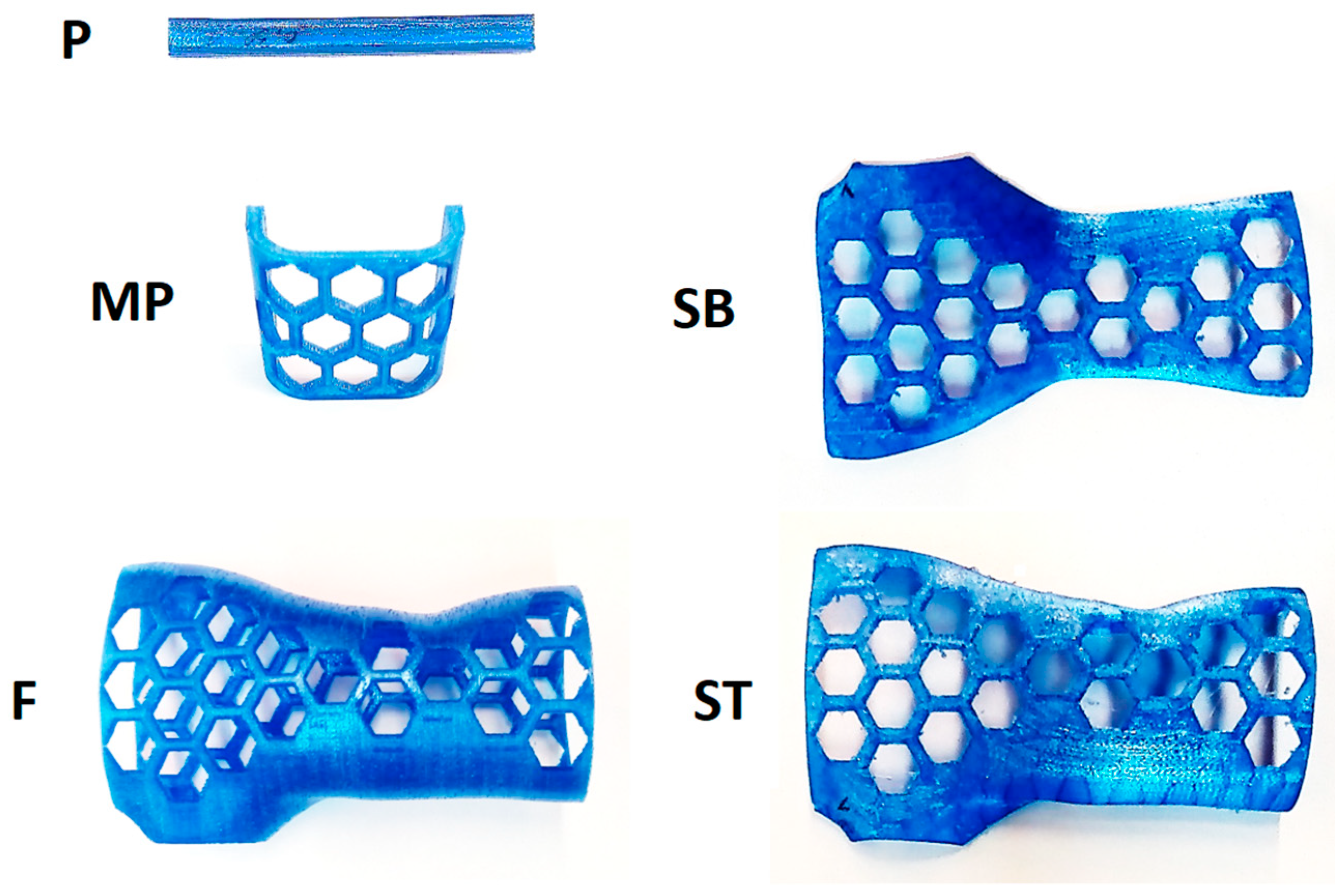
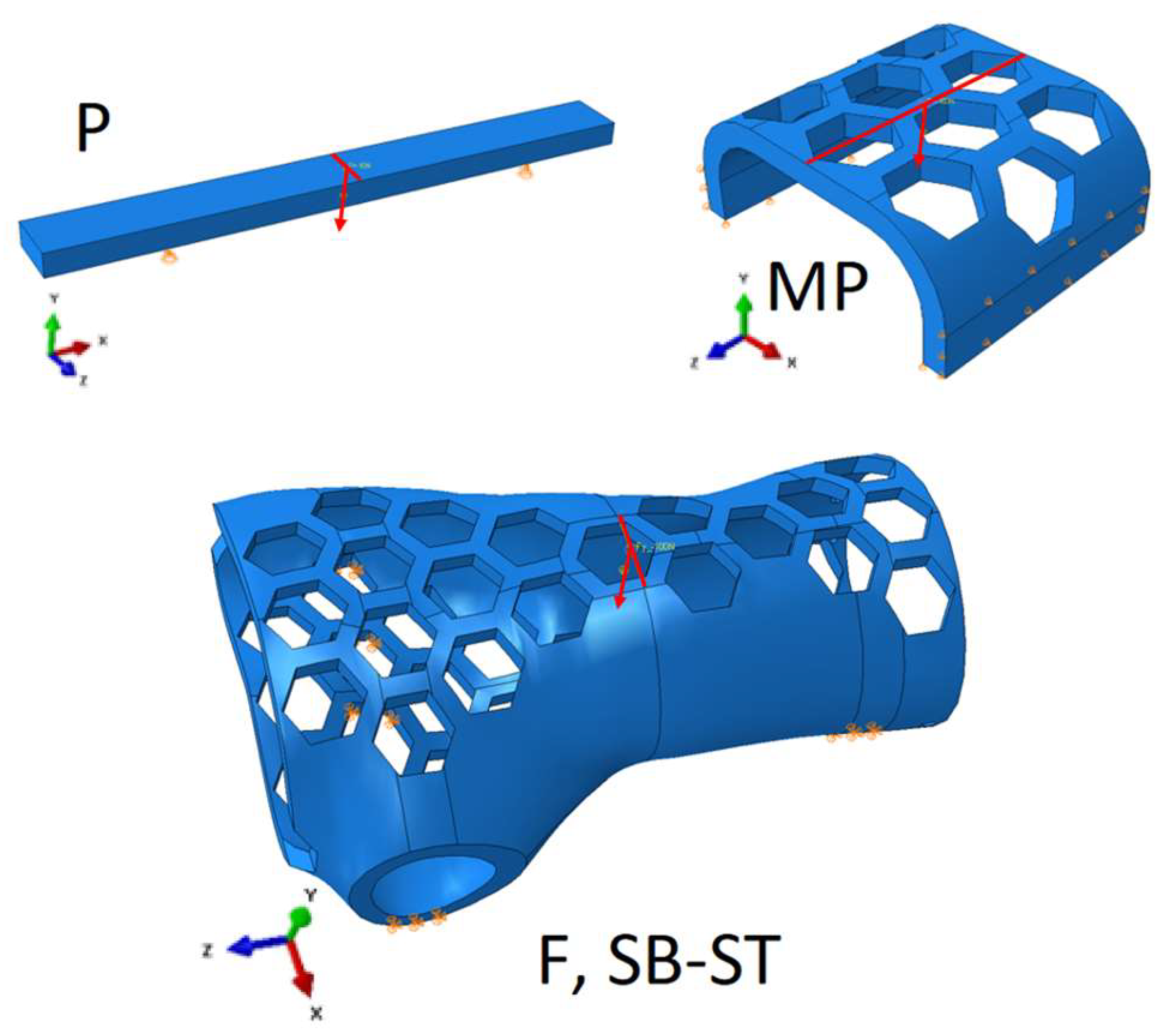
- sample preparation: standard 3-point bending samples, samples of the orthotic center without and with openings, and samples of the entire orthotic shape,
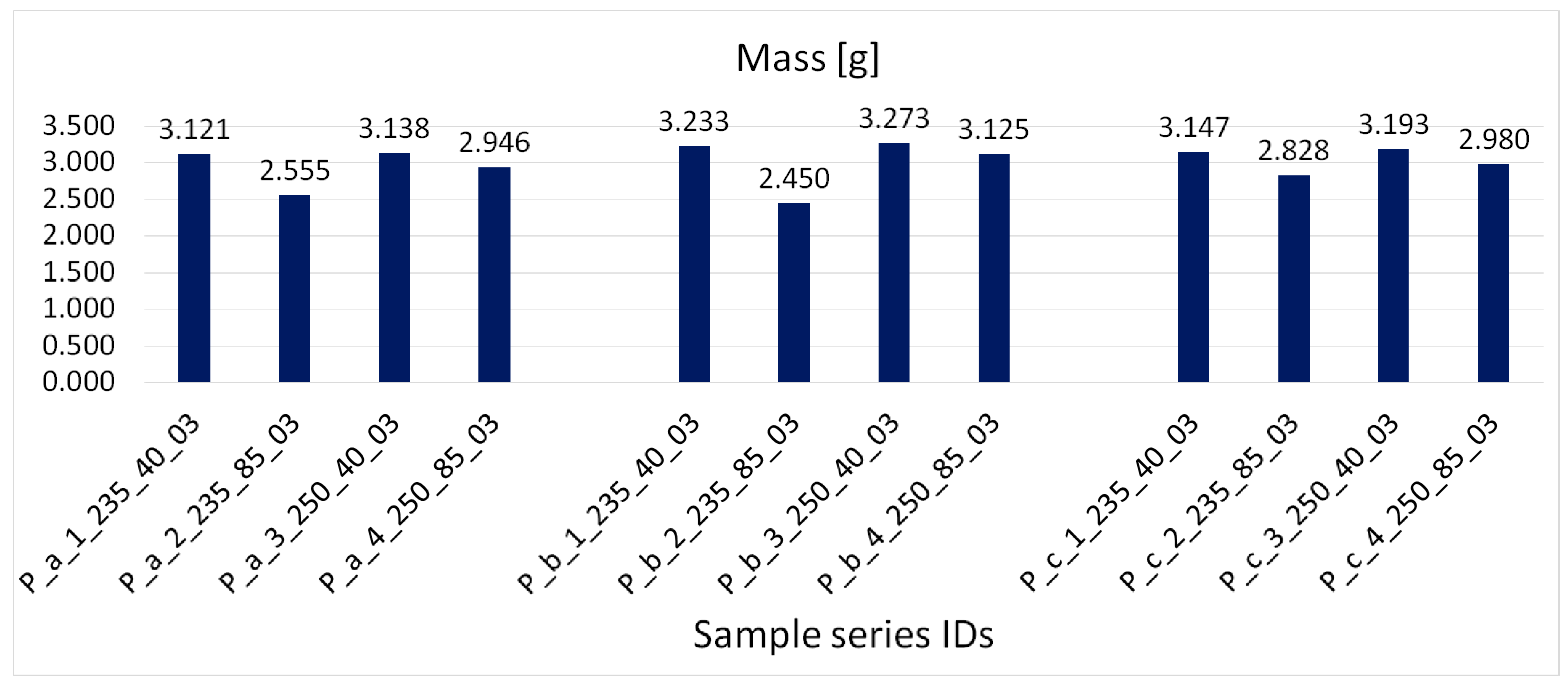
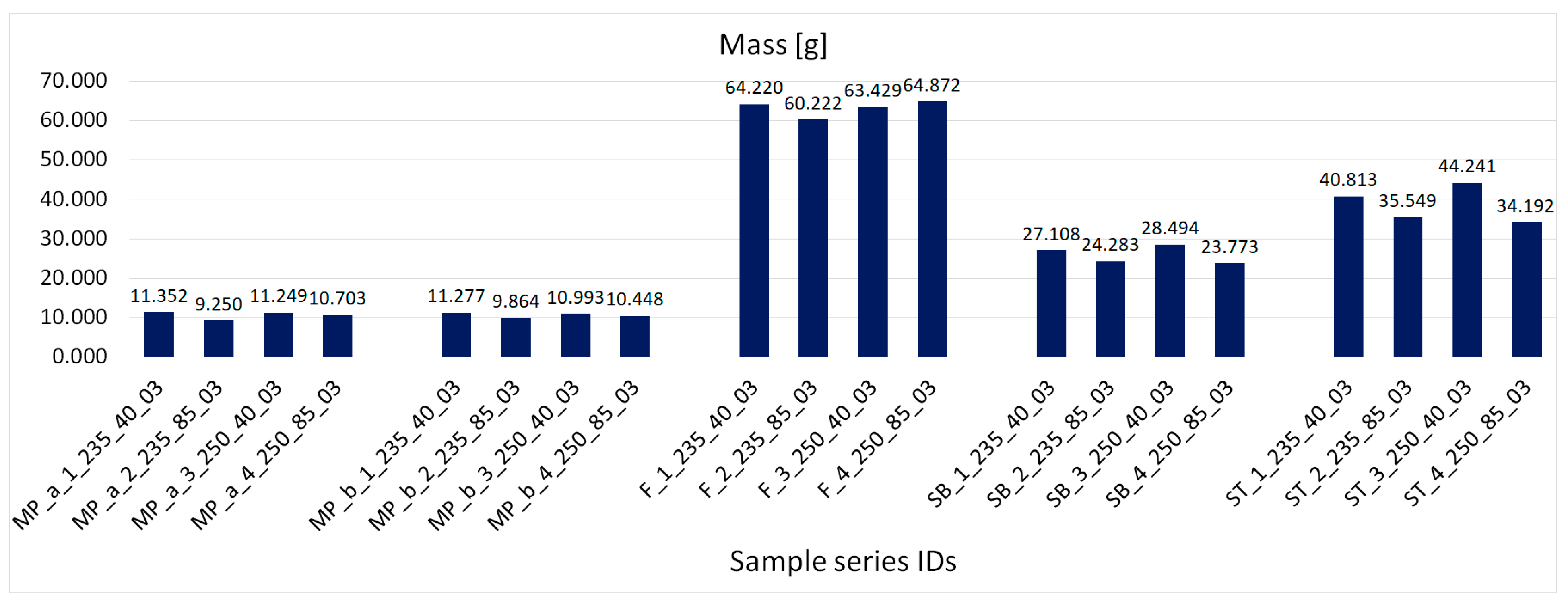
- measuring the density of the samples,
- bending test,
- modeling and simulation (FEM) of sample loads,
- comparison of displacement values from experiment and simulation, and determination of measured elastic modulus based on simulation results.
- Ee—real value of elastic modulus [MPa],
- Es—simulated value of elastic modulus [MPa],
- Uie—experimentally obtained displacement value [mm],
- Uis—simulated displacement value [mm].
3.2. Manufacturing of Samples
- extrusion temperature 220–250 [°C].
- density 1.29 [g/cm3],
- heat deflection temperature (HDT) 78 [°C].
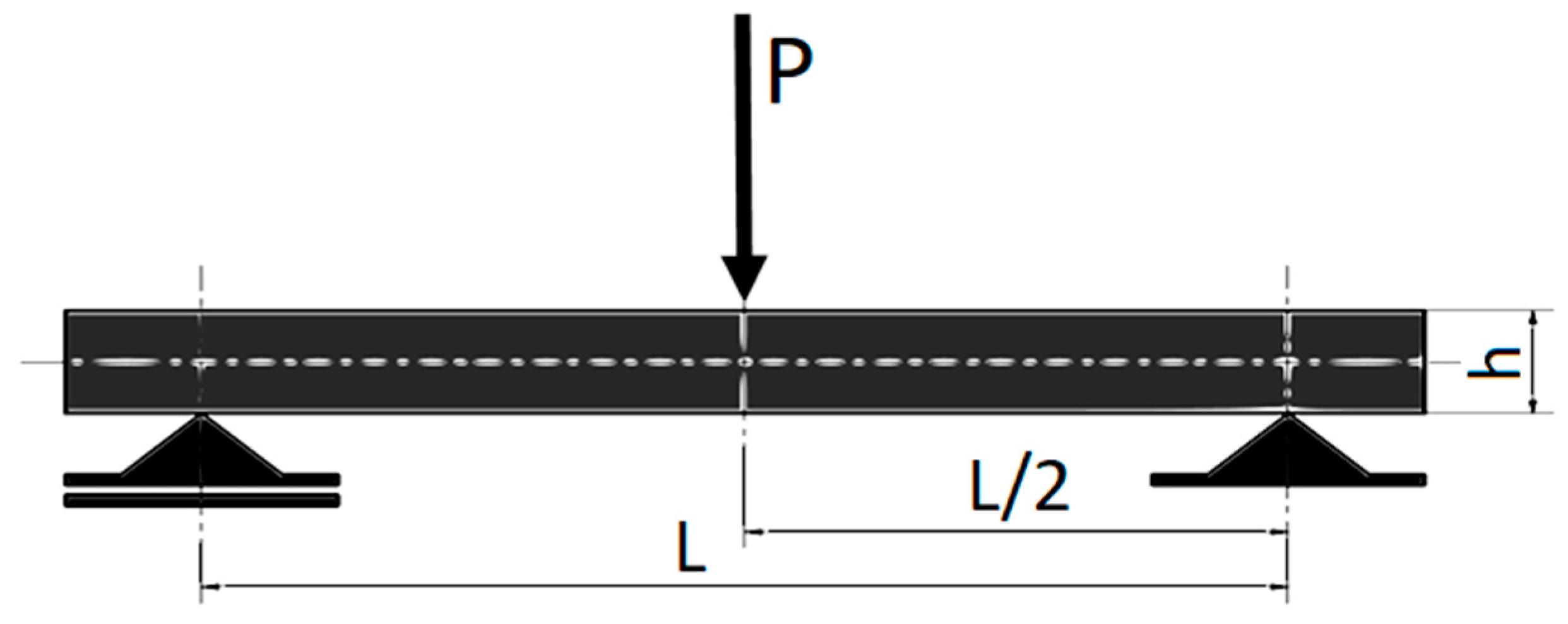
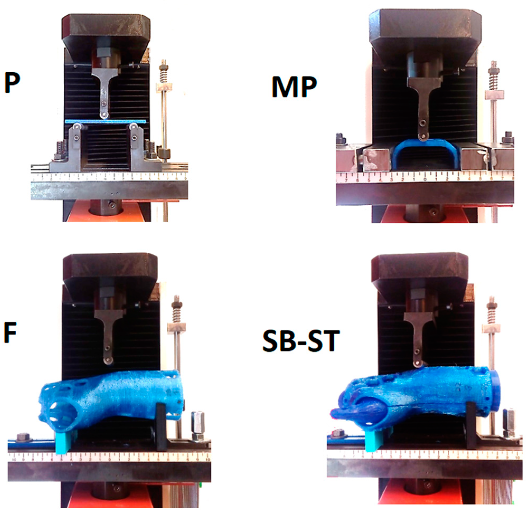
3.3. Methodology of Bending Tests
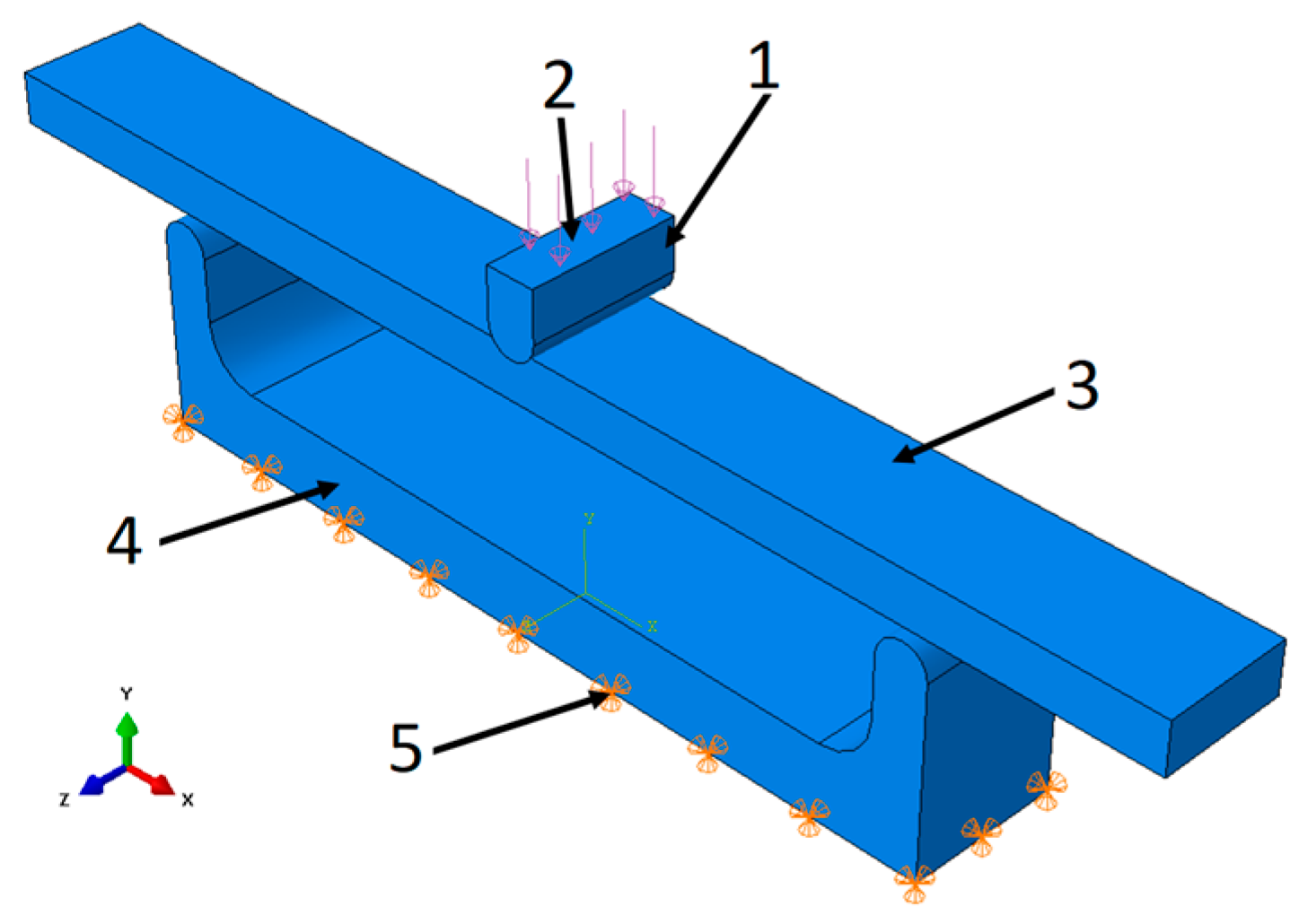
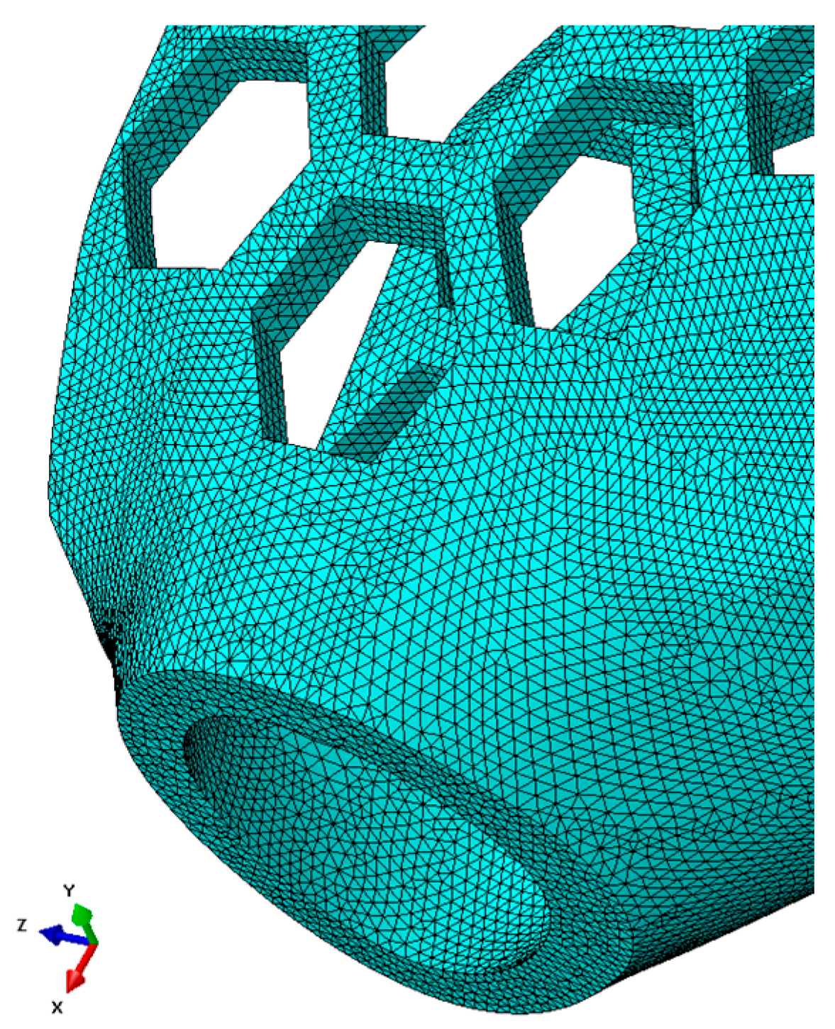
3.4. Methodology of Finite Element Analysis
4. Results
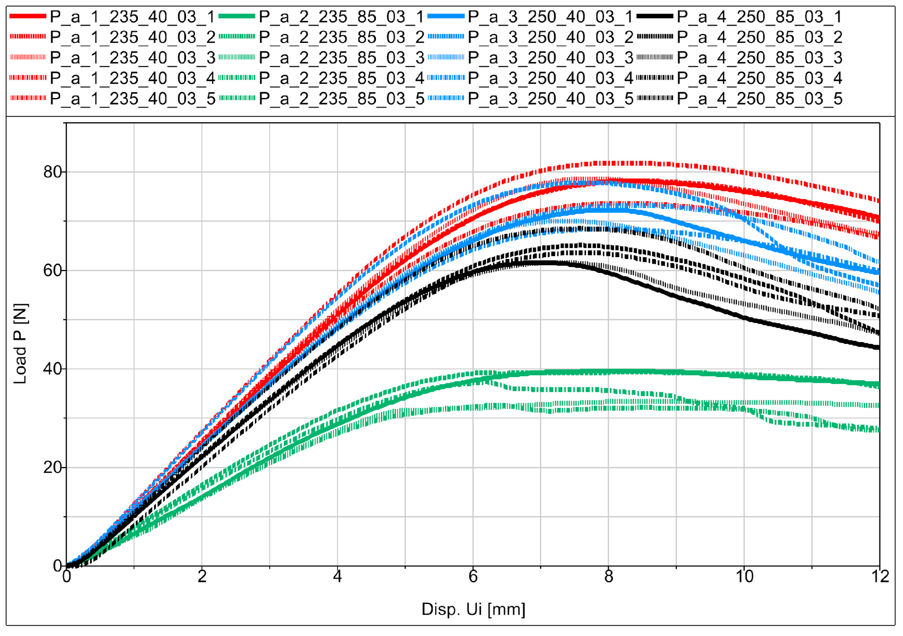
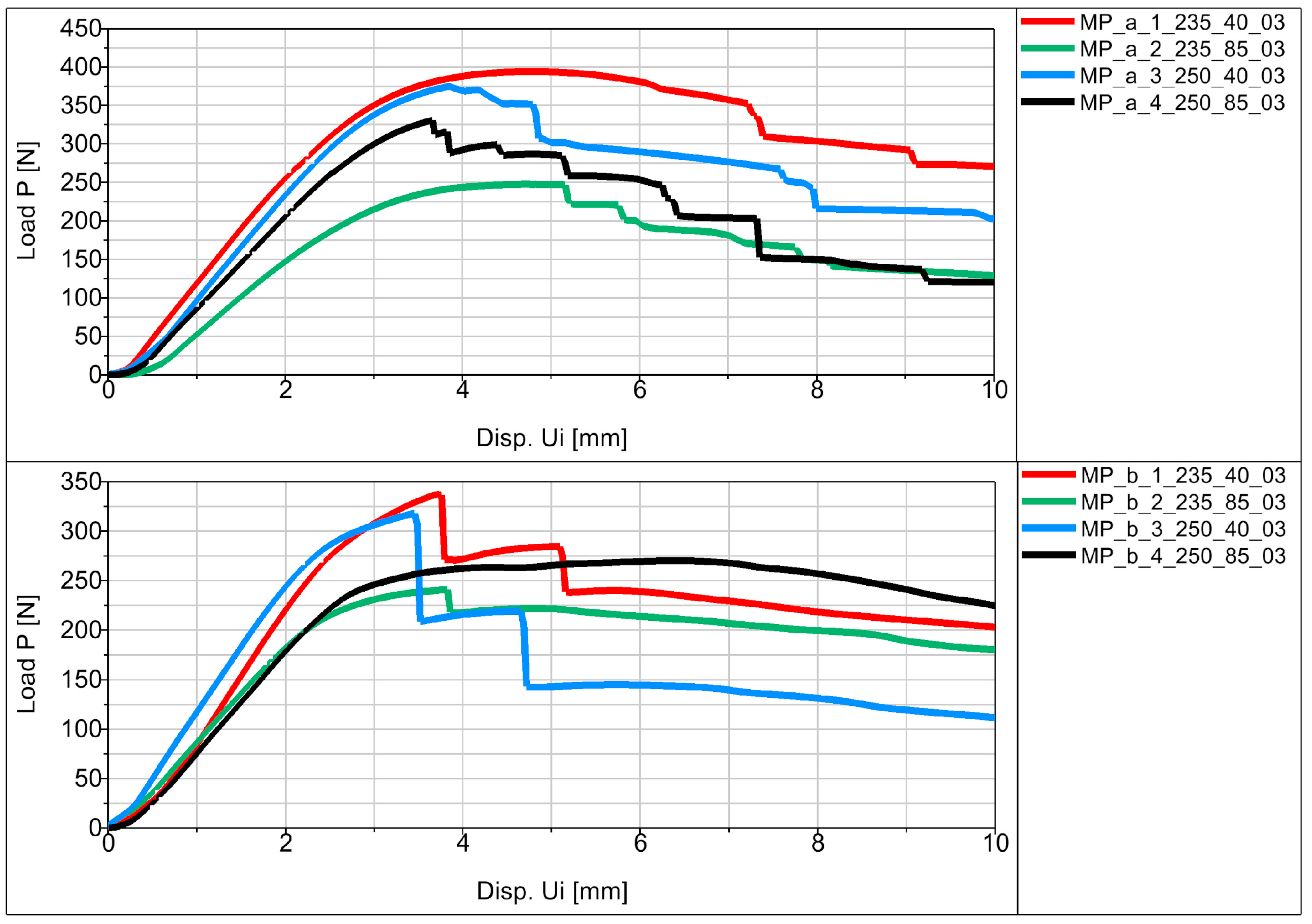
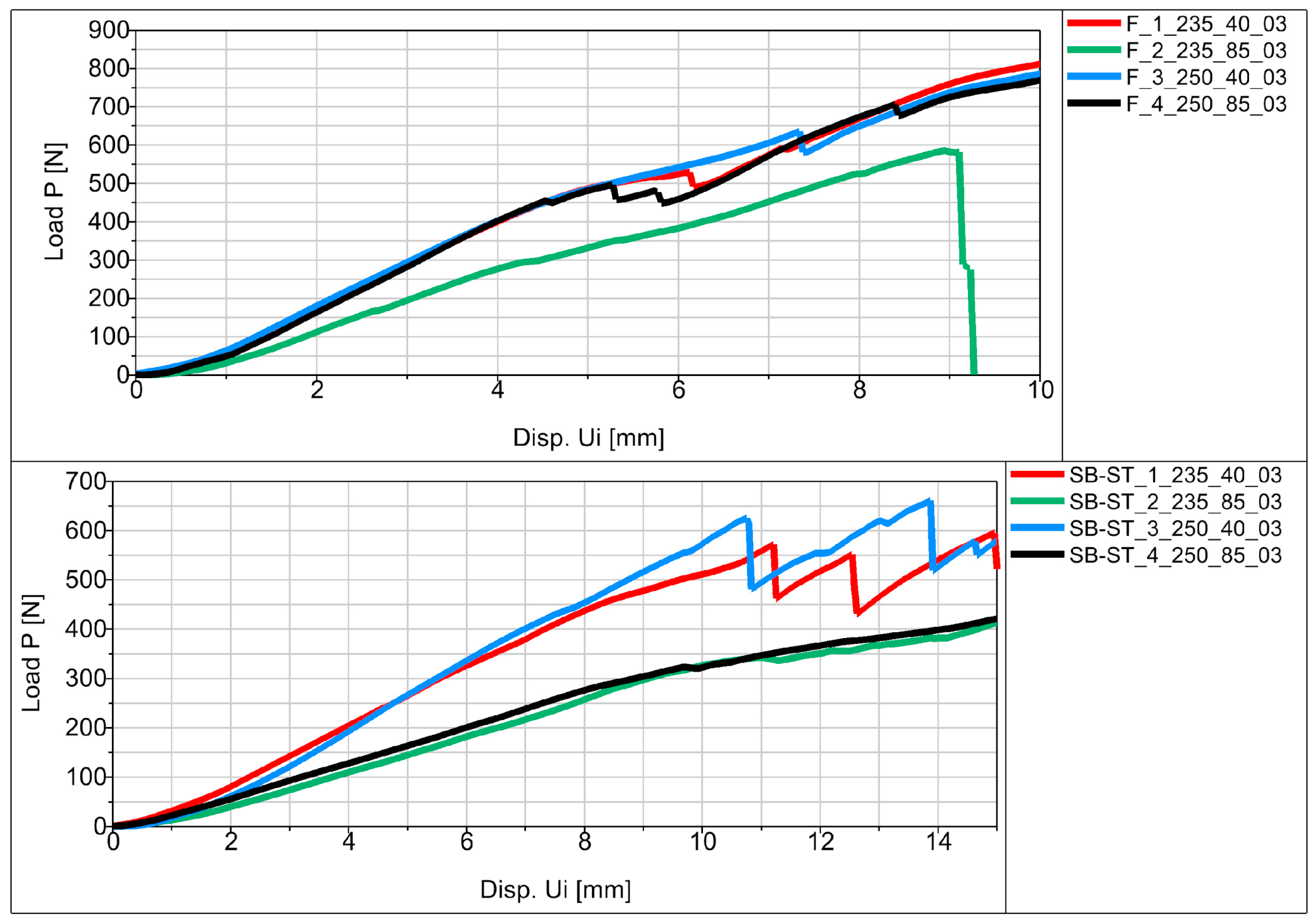
4.1. Bending Test Results
4.2. Bending Test Results
4.3. Finite Element Analysis Results
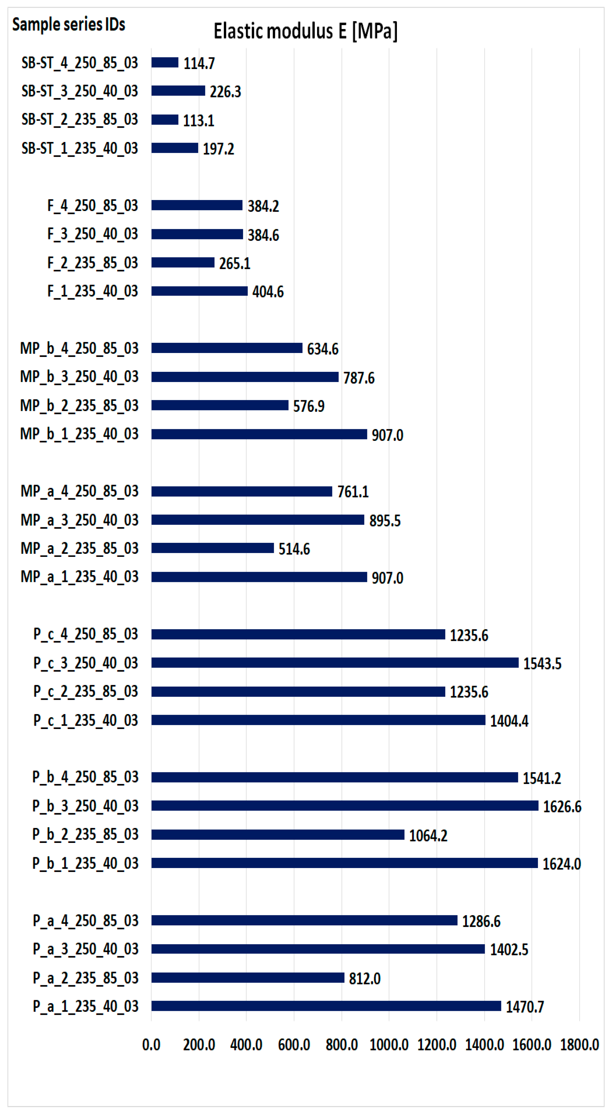
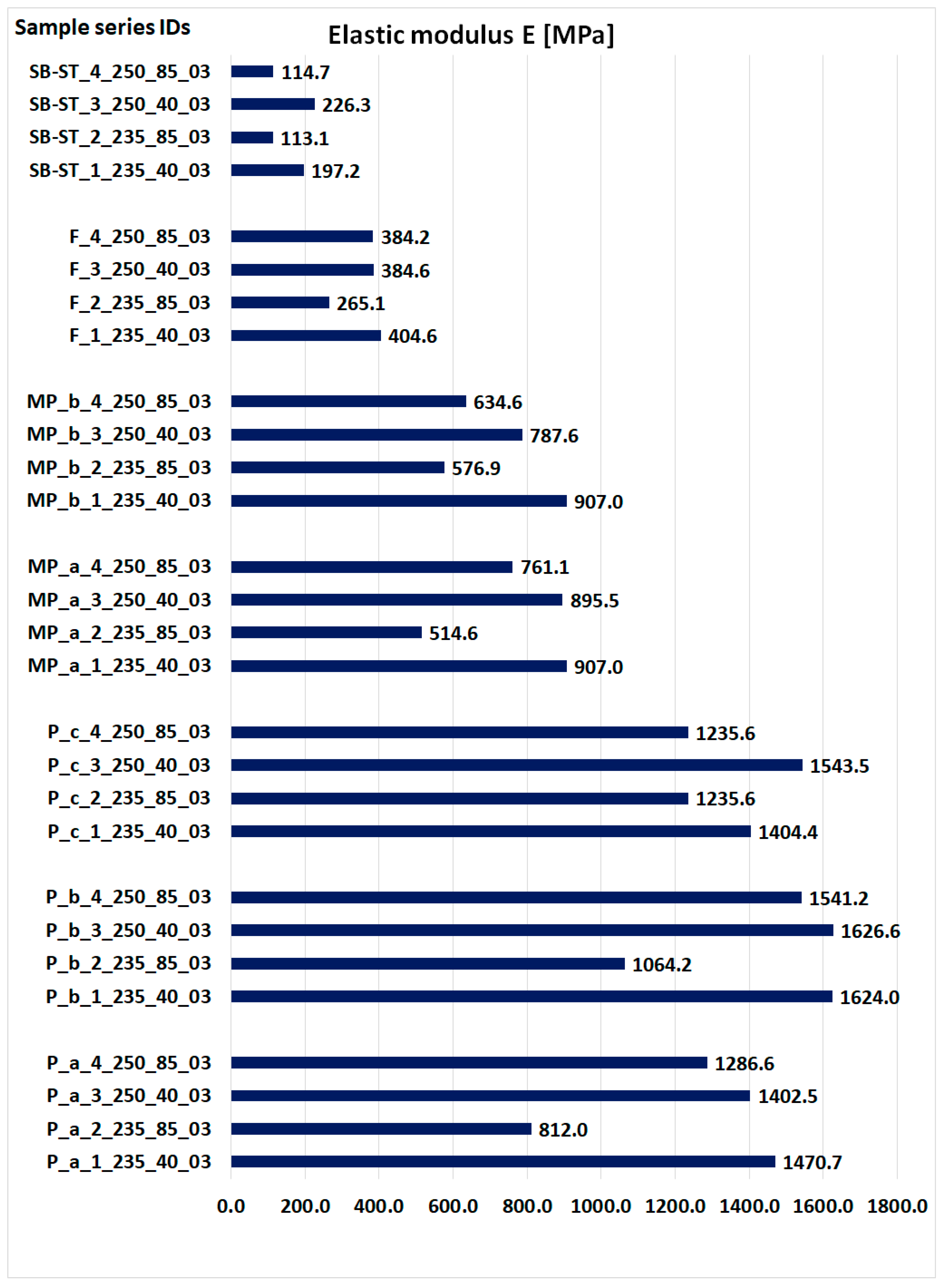
4.4. Elastic Modulus of Samples
4.5. Result Comparison
5. Discussion
5.1. Effect of Printing Parameter Variations in Weight and Density
5.2. Effect of Printing Parameter Variations on Strength
6. Conclusions
Author Contributions
Funding
Institutional Review Board Statement
Informed Consent Statement
Data Availability Statement
Conflicts of Interest
References
- Łukaszewski, K.; Wichniarek, R.; Górski, F. Determination of the Elasticity Modulus of Additively Manufactured Wrist Hand Orthoses. Materials 2020, 13, 4379. [Google Scholar] [CrossRef]
- Raj, R.; Dixit, A.R.; Łukaszewski, K.; Wichniarek, R.; Rybarczyk, J.; Kuczko, W.; Górski, F. Numerical and Experimental Mechanical Analysis of Additively Manufactured Ankle–Foot Orthoses. Materials 2022, 15, 6130. [Google Scholar] [CrossRef] [PubMed]
- Štefanovič, B.; Danko, M.; Michalíková, M.; Bednarčíková, L.; Rajťúková, V.; Tóth, T.; Trebuňová, M.; Hudák, R.; Živčák, J. Orthoses Development Using Modern Technologies. In Prosthetics and Orthotics; IntechOpen: London, UK, 2021. [Google Scholar] [CrossRef]
- Liu, Z.; Zhang, P.; Yan, M.; Xie, Y.; Huang, G. Additive manufacturing of specific ankle-foot orthoses for persons after stroke: A preliminary study based on gait analysis data. Math. Biosci. Eng. 2019, 16, 8134–8143. [Google Scholar] [CrossRef] [PubMed]
- Sakib-Uz-Zaman, C.; Khondoker, M.A.H. Polymer-Based Additive Manufacturing for Orthotic and Prosthetic Devices: Industry Outlook in Canada. Polymers 2023, 15, 1506. [Google Scholar] [CrossRef] [PubMed]
- Wojciechowski, E.; Chang, A.Y.; Balassone, D.; Ford, J.; Cheng, T.L.; Little, D.; Menezes, M.P.; Hogan, S.; Burns, J. Feasibility of designing, manufacturing and delivering 3D printed ankle-foot orthoses: A systematic review. J. Foot Ankle Res. 2019, 12, 11. [Google Scholar] [CrossRef] [PubMed]
- Available online: https://get3d.pl/2020/05/13/jak-drukowac-z-petg/ (accessed on 21 August 2023).
- ISO-ISO/ASTM 52900:2021(E); Additive Manufacturing—General Principles—Fundamentals and Vocabulary. ISO/ASTM International: West Conshohocken, PA, USA, 2022.
- Banaszewski, J.; Pabiszczak, M.; Pastusiak, T.; Buczkowska, A.; Kuczko, W.; Wichniarek, R.; Górski, F. 3D printed models in mandibular reconstruction with bony free flaps. J. Mater. Sci. Mater. Med. 2018, 29, 23. [Google Scholar]
- Shilo, D.; Emodi, O.; Blanc, O.; Noy, D.; Rachmiel, A. Printing the Future-Updates in 3D Printing for Surgical Applications. Rambam Maimonides Med. J. 2018, 9, e0020. [Google Scholar] [CrossRef] [PubMed]
- Evill, J. Cortex. Available online: https://www.evilldesign.com/cortex (accessed on 7 January 2023).
- Gorski, F.; Wichniarek, R.; Kuczko, W.; Hamrol, A. Selection of Fused Deposition Modeling Process Parameters Using Finite Element Analysis and Genetic Algorithms. J. Mult.-Valued Log. Soft Comput. 2019, 32, 293–311. [Google Scholar]
- Novakova-Marcincinova, L.; Novak-Marcincin, J.; Barna, J.; Torok, J. Special materials used in FDM rapid prototyping technology ap-plication. In Proceedings of the 2012 IEEE 16th International Conference on Intelligent Engineering Systems (INES), Lisbon, Portugal, 13–15 June 2012; pp. 73–76. [Google Scholar]
- Stano, G.; Ovy, S.M.A.I.; Edwards, J.R.; Cianchetti, M.; Percoco, G.; Tadesse, Y. One-shot additive manufacturing of robotic finger with embedded sensing and actuation. Int. J. Adv. Manuf. Technol. 2023, 124, 467–485. [Google Scholar] [CrossRef]
- Sepulveda-Navarrete, D.A.; Gutierrez, P.S.; Lopes, A.; Rome, J.I.; Goyal, V.K.; Espalin, D. Ultrasonically embedded wires in multi-material parts produced by hybrid additive manufacturing. Addit. Manuf. 2023, 73, 103662. [Google Scholar] [CrossRef]
- Wang, T.M.; Xi, J.-T.; Jin, Y. A model research for prototype warp deformation in the FDM process. Int. J. Adv. Manuf. Technol. 2007, 33, 1087–1096. [Google Scholar] [CrossRef]
- Pilipovi, A.; Raos, P.; Šercer, M. Experimental analysis of properties of materials for rapid prototyping. Int. J. Adv. Manuf. Technol. 2009, 40, 105–115. [Google Scholar] [CrossRef]
- Abaqus, version 6.12. Analysis User’s Manual Volume IV: Elements. Dassault Systèmes: Johnston, RI, USA, 2012.
- Aguilar-Martín, J.J.; Yagüe-Fabra, J.A.; Martínez, J.; Diéguez, J.L.; Ares, E.; Pereira, A.; Pérez, J.A. Comparative between FEM Models for FDM Parts and their Approach to a Real Mechanical Behaviour. Procedia Eng. 2013, 63, 878–884. [Google Scholar]
- Górski, F.; Kuczko, W.; Weiss, W.; Wichniarek, R.; Żukowska, M. Prototyping of an Individualized Multi-Material Wrist Orthosis Using Fused Deposition Modelling. Adv. Sci. Technol. Res. J. 2019, 13, 39–47. [Google Scholar] [CrossRef] [PubMed]
- Kuznetsov, V.; Solonin, A.; Tavitov, A.; Urzhumtsev, O.; Vakulik, A. Increasing strength of FFF three-dimensional printed parts by influencing on temperature-related parameters of the process. Rapid Prototyp. J. 2019, 26, 107–121. [Google Scholar] [CrossRef]
- Srilakshmi, C.; Rao, G.S.; Kumar, J.S. A Review on Damage Modelling and Analysis of Composites. Mater. Sci. Eng. 2021, 1185, 012021. [Google Scholar] [CrossRef]
- Cazon, A.; Kelly, S.; Paterson, A.M.; Bibb, R.J.; Campbell, R.I. Analysis and comparison of wristsplint designs using the finite element method: Multi-material three-dimensionalprinting compared to typical existing practice with thermoplastics. Proc. Inst. Mech. Eng. Part H J. Eng. Med. 2017, 231, 881–897. [Google Scholar] [CrossRef] [PubMed]
- Marques, M.A.; Mendes, E.; Ramos, N.V.; Pinto, V.C.; Vaz, M.A. Finite-element analysis of ankle-foot orthosis to predict fracture conditions during gait. In Proceedings of the 1st ICH Gaia-Porto, Porto, Portugal, 1 January 2010. [Google Scholar]
- Chen, R.K.; Chen, L.; Tai, B.L.; Wang, Y.; Shih, A.J.; Wensman, J. Additive Manufacturing of Personalized Ankle-Foot Orthosis. In Proceedings of the Transactions of the North American Manufacturing Research Institution of SME (NAMRC42), Detroit, MI, USA, 9–13 June 2014; Volume 42. [Google Scholar]
- Hendricks, A.; Nevin, S.; Wikoff, C.; Dougherty, M.; Orlita, J.; Noorani, R. The Low-Cost Design and 3D Printing of Structural Knee Orthotics for Athletic Knee Injury Patients. Int. J. Biomed. Biol. Eng. 2018, 12, 445–451. [Google Scholar]
- Cerda-Avila, S.N.; Medellín-Castillo, H.I.; de Lange, D.F. Analysis and Numerical Simulation of the Structural Performance of Fused Deposition Modeling Samples with Variable Infill Values. ASME J. Eng. Mater. Technol. 2019, 141, 021005. [Google Scholar] [CrossRef]
- Li, J.; Tanaka, H. Rapid customization system for 3D-printedsplint using programmable modelling technique—A practical approach. 3D Print. Med. 2018, 4, 5. [Google Scholar] [CrossRef] [PubMed]
- Available online: https://sklep.rosa3d.pl/product/filament-pet-g-standard-175-mm-blue-sky-08kg/ (accessed on 21 August 2023).
- ISO 178:2019; Plastics—Determination of Flexural Properties. ISO: Geneva, Switzerland, 2019.


| Sample No. | Extrusion Temperature [°C] | Extrusion Speed [mm/s] | Layer Thickness [mm] | Machine | Material |
|---|---|---|---|---|---|
| 1 | 235 | 40 | 0.3 | FlashForge Creator Pro | PET-G |
| 2 | 235 | 85 | |||
| 3 | 250 | 40 | |||
| 4 | 250 | 85 |
| Series Designation | Shape of Element | Type | Global Size | Amount of Nodes | Amount of Elements |
|---|---|---|---|---|---|
| P | Triangular | C3D10 | 1 mm | 42,517 | 27,456 |
| MP | Triangular | C3D10 | 1 mm | 158,610 | 102,752 |
| F, SB-ST | Triangular | C3D10 | 1 mm | 856,431 | 561,274 |
| Series | Force Value p Displacement Ui | Result as a Colorful Map |
|---|---|---|
| P | P = 10 [N] Ui = 1.028 [mm] |  |
| MP | P = 100 [N] Ui = 0.634 [mm] | 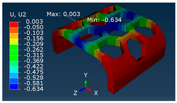 |
| F, SB-ST | P = 100 [N] Ui = 0.320 [mm] | 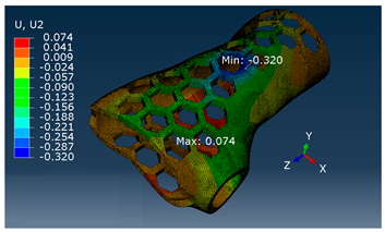 |
| Series Designation | Density [g/cm3] | Obtained E Modulus [MP] | The Maximum Force Obtained from the Average P [N] | Displacement Value from Maximum Force Ui [mm] |
|---|---|---|---|---|
| P_a_1_235_40_03 | 0.780 | 1470.7 | 78.04 | 8.25 |
| P_a_2_235_85_03 | 0.639 | 812.0 | 36.00 | 6.31 |
| P_a_3_250_40_03 | 0.785 | 1402.5 | 72.16 | 7.79 |
| P_a_4_250_85_03 | 0.736 | 1286.6 | 63.96 | 7.59 |
| P_b_1_235_40_03 | 0.808 | 1624.0 | 103.16 | 7.39 |
| P_b_2_235_85_03 | 0.613 | 1064.2 | 41.56 | 5.11 |
| P_b_3_250_40_03 | 0.818 | 1626.6 | 104.76 | 7.35 |
| P_b_4_250_85_03 | 0.781 | 1541.2 | 98.32 | 7.29 |
| P_c_1_235_40_03 | 0.787 | 1404.4 | 68.44 | 5.42 |
| P_c_2_235_85_03 | 0.707 | 1235.6 | 51.80 | 4.69 |
| P_c_3_250_40_03 | 0.798 | 1543.5 | 61.60 | 4.24 |
| P_c_4_250_85_03 | 0.745 | 1235.6 | 35.00 | 3.06 |
| MP_a_1_235_40_03 | 0.758 | 907.0 | 394.20 | 4.80 |
| MP_a_2_235_85_03 | 0.618 | 514.6 | 247.40 | 4.83 |
| MP_a_3_250_40_03 | 0.751 | 895.5 | 374.60 | 3.86 |
| MP_a_4_250_85_03 | 0.715 | 761.1 | 330.87 | 3.66 |
| MP_b_1_235_40_03 | 0.753 | 907.0 | 337.00 | 3.73 |
| MP_b_2_235_85_03 | 0.659 | 576.9 | 241.133 | 3.83 |
| MP_b_3_250_40_03 | 0.734 | 787.6 | 318.27 | 3.46 |
| MP_b_4_250_85_03 | 0.698 | 634.6 | 270.4 | 3.57 |
| F_1_235_40_03 | 0.786 | 404.6 | 829.40 | 10.68 |
| F_2_235_85_03 | 0.737 | 265.1 | 882.50 | 10.95 |
| F_3_250_40_03 | 0.777 | 384.6 | 585.60 | 8.94 |
| F_4_250_85_03 | 0.794 | 384.2 | 932.60 | 11.79 |
| SB-ST_1_235_40_03 | 0.862 | 197.2 | 649.10 | 17.79 |
| SB-ST_2_235_85_03 | 0.772 | 113.1 | 605.20 | 22.09 |
| SB-ST_3_250_40_03 | 0.906 | 226.3 | 741.30 | 17.45 |
| SB-ST_4_250_85_03 | 0.756 | 114.7 | 588.00 | 22.64 |
Disclaimer/Publisher’s Note: The statements, opinions and data contained in all publications are solely those of the individual author(s) and contributor(s) and not of MDPI and/or the editor(s). MDPI and/or the editor(s) disclaim responsibility for any injury to people or property resulting from any ideas, methods, instructions or products referred to in the content. |
© 2023 by the authors. Licensee MDPI, Basel, Switzerland. This article is an open access article distributed under the terms and conditions of the Creative Commons Attribution (CC BY) license (https://creativecommons.org/licenses/by/4.0/).
Share and Cite
Łukaszewski, K.; Raj, R.; Karwasz, A. Mechanical Evaluation of PET-G 3D-Printed Wrist-Hand Orthosis: An Integrated Experimental and Numerical Approach. Materials 2023, 16, 6132. https://doi.org/10.3390/ma16186132
Łukaszewski K, Raj R, Karwasz A. Mechanical Evaluation of PET-G 3D-Printed Wrist-Hand Orthosis: An Integrated Experimental and Numerical Approach. Materials. 2023; 16(18):6132. https://doi.org/10.3390/ma16186132
Chicago/Turabian StyleŁukaszewski, Krzysztof, Ratnesh Raj, and Anna Karwasz. 2023. "Mechanical Evaluation of PET-G 3D-Printed Wrist-Hand Orthosis: An Integrated Experimental and Numerical Approach" Materials 16, no. 18: 6132. https://doi.org/10.3390/ma16186132
APA StyleŁukaszewski, K., Raj, R., & Karwasz, A. (2023). Mechanical Evaluation of PET-G 3D-Printed Wrist-Hand Orthosis: An Integrated Experimental and Numerical Approach. Materials, 16(18), 6132. https://doi.org/10.3390/ma16186132