
Basic Design Parameters Influencing on Axial Stiffness of the Spiral Wound Gasket


Abstract
:1. Introduction
2. Materials and Methods
2.1. Experimental Research
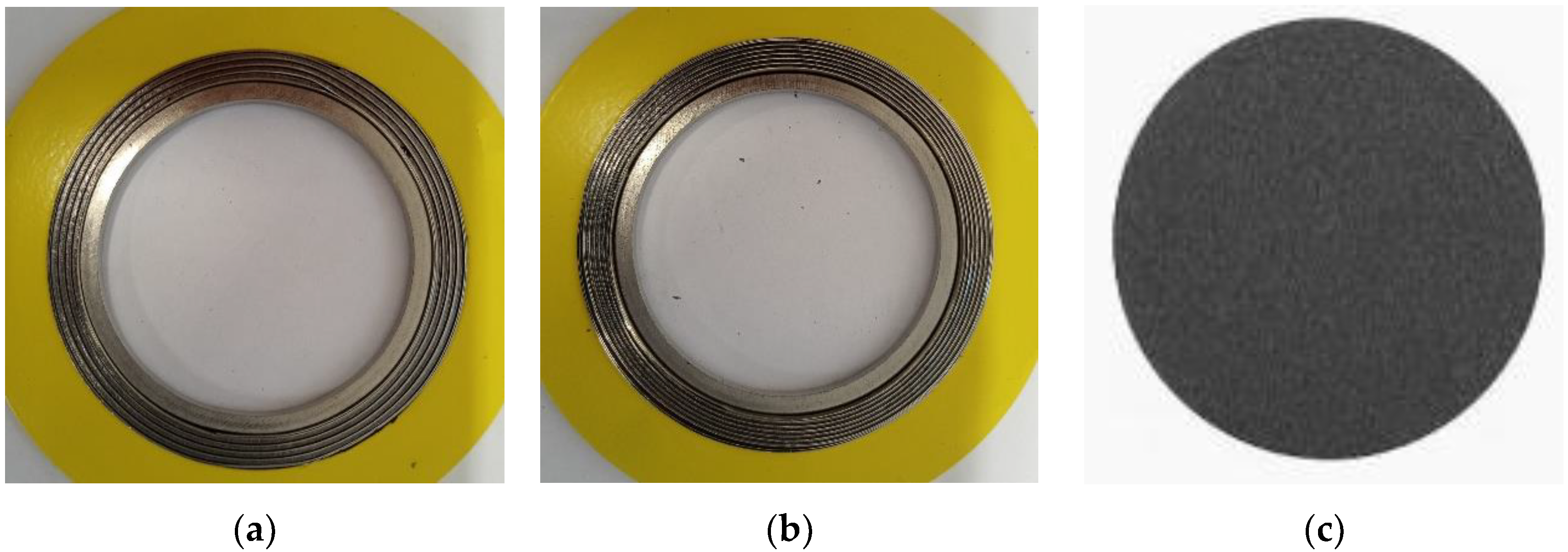
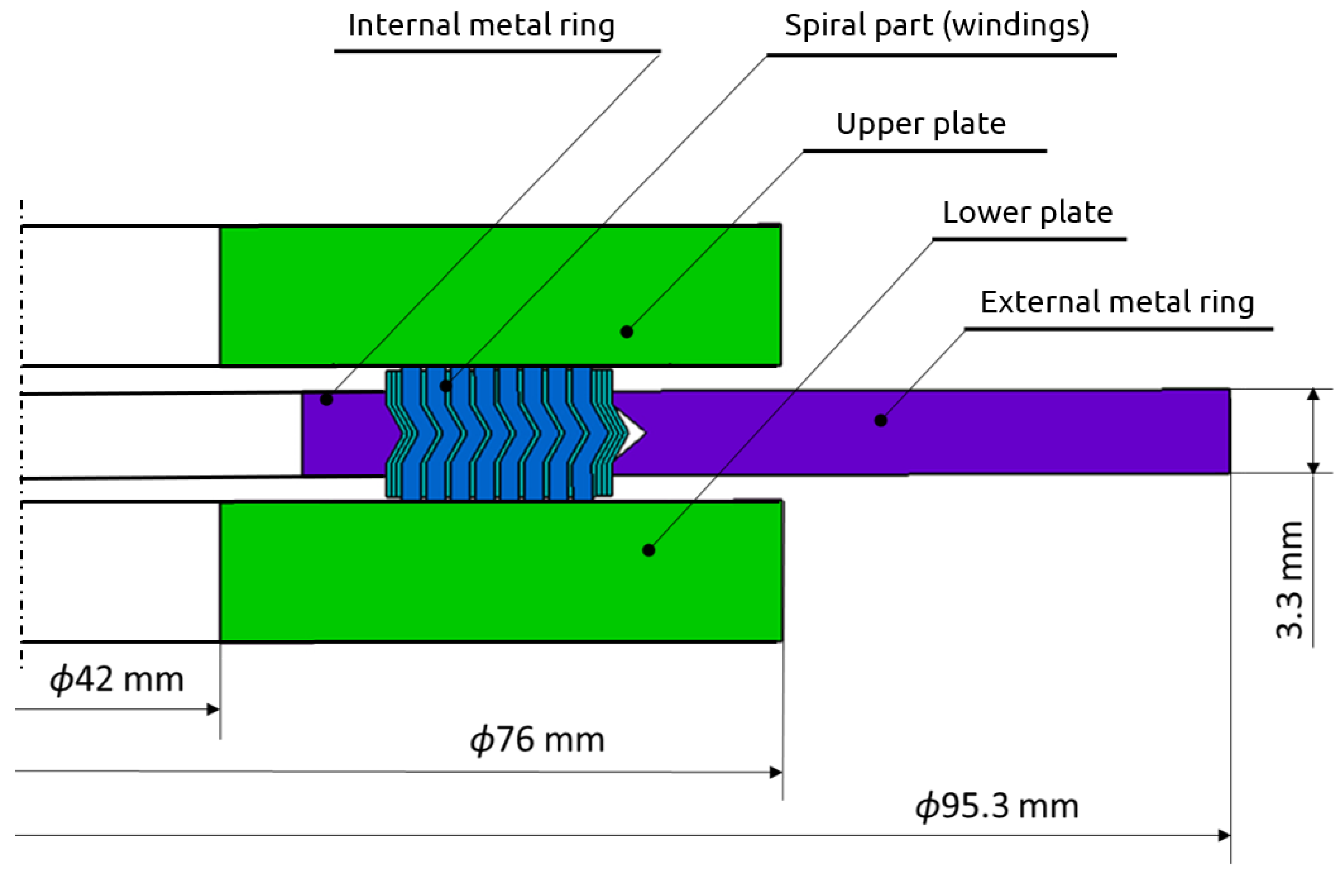
2.1.1. Research Object
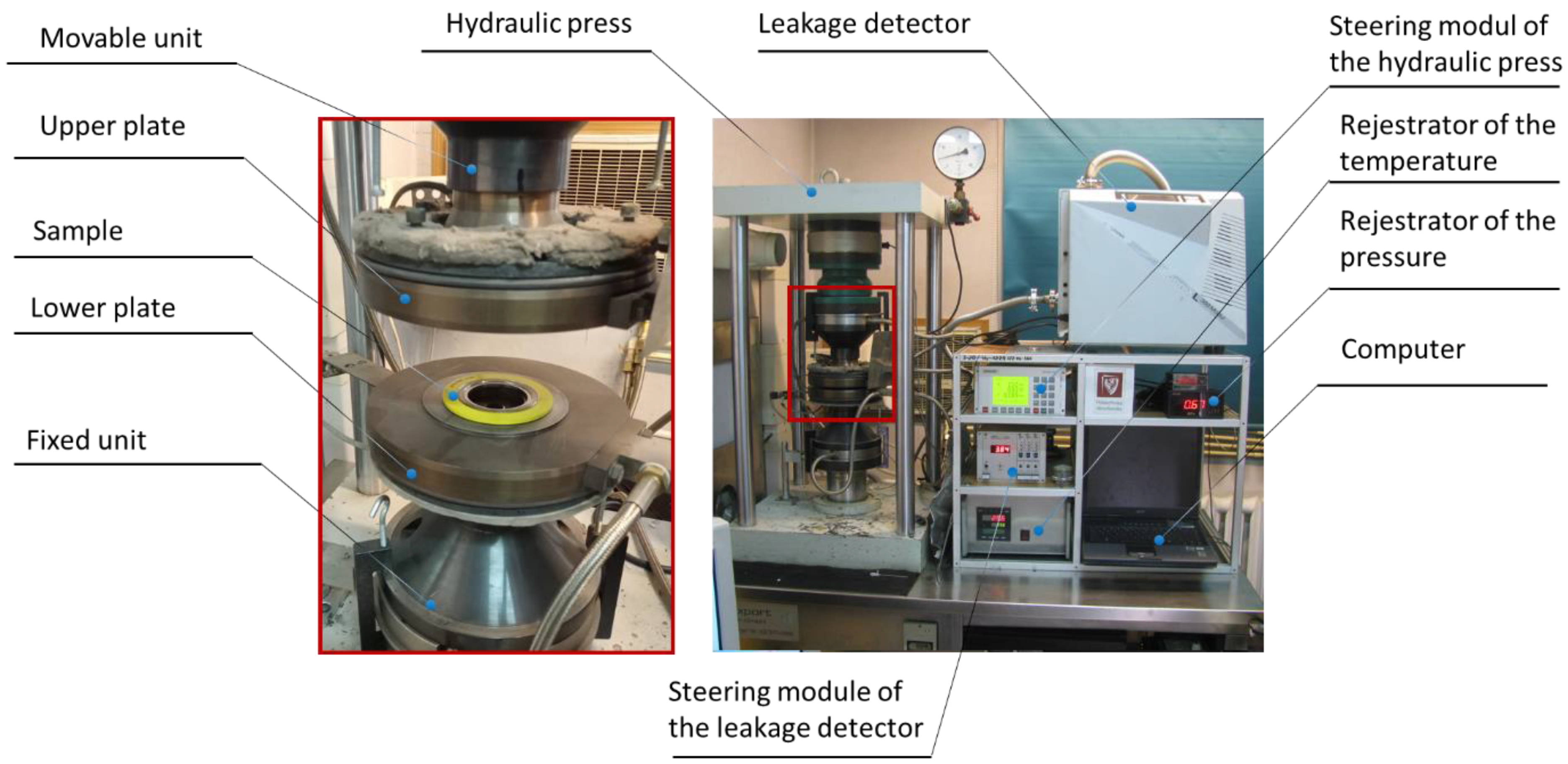
2.1.2. Test Stand
2.1.3. Research Procedures
- 1.
- Measurements of the geometry of the tested sample (thickness and external and internal diameter). Measurements were made at four points that were evenly distributed around the circumference (every 90 degrees);
- 2.
- Central location of a sample on the lower measuring plate of the test stand;
- 3.
- Starting the program that controls the displacement of the upper unit of the test stand in order to induce gradual compression of the tested sample; the computer program (controlling the displacement of the upper unit of the test stand) implemented the following load scenario: the compression speed of the sample—5 MPa/min. In the case of the spiral gaskets, the maximum displacement of the top plate of the test stand was 0.9 mm, whereas in the case of testing the filler, the maximum plate pressure (on the surface of the disc) was set as 150 MPa;
- 4.
- Simultaneously with the implementation of point 3 of the procedure, the program archived data in the form of the degree of compression of the tested sample and the force or pressure exerted on the surface of the sample;
- 5.
- After measuring the compression of the samples, their geometry was remeasured in accordance with point 3 of the procedure.
- 1.
- Measurements of the geometry of the tested sample (thickness and external and internal diameter); measurements were made at four points that were evenly distributed around the circumference (every 90 degrees);
- 2.
- Central placement of a sample on the lower measuring plate of the test stand;
- 3.
- Placement of the secondary seal that constitutes a collector for measuring the tested medium leaking from the gasket;
- 4.
- Starting the program that controls the displacement of the upper plate of the test stand in order to cause gradual compression of the tested sample. The computer program controlling the displacement of the upper platform plate implemented the following load scenario: the compression speed of the sample was 5 MPa/min. The contact pressure at which leakage was measured was 5, 10, 20, 30, 40, 50, 60, 80, 100, 120 and 140 MPa, respectively. At each load point, helium was automatically fed into the gasket at a pressure of 40 bar. The test stand control program automatically measured the leakage using a spectrometric helium detector.
2.2. Numerical Calculations
- —response function; in the analysed case, it is the axial stiffness of the gasket;
- xi, xj—decision parameters (design factors);
- b0, bi, bii, bij—polynomial coefficients, which are calculated according to the following dependencies;
- —results obtained from the tests.
- Height of the vertical part of the profile of metal windings h1s within the range from 0.8 to 1.6 mm;
- Angle of inclination of the central part of the metal windings α within the range of 45 to 70 degrees;
- Winding density of the spiral gasket ρg ranging from 1.18 turns/mm to 1.46 turns/mm; the winding density of the filler determined its thickness after being wound into a spiral.
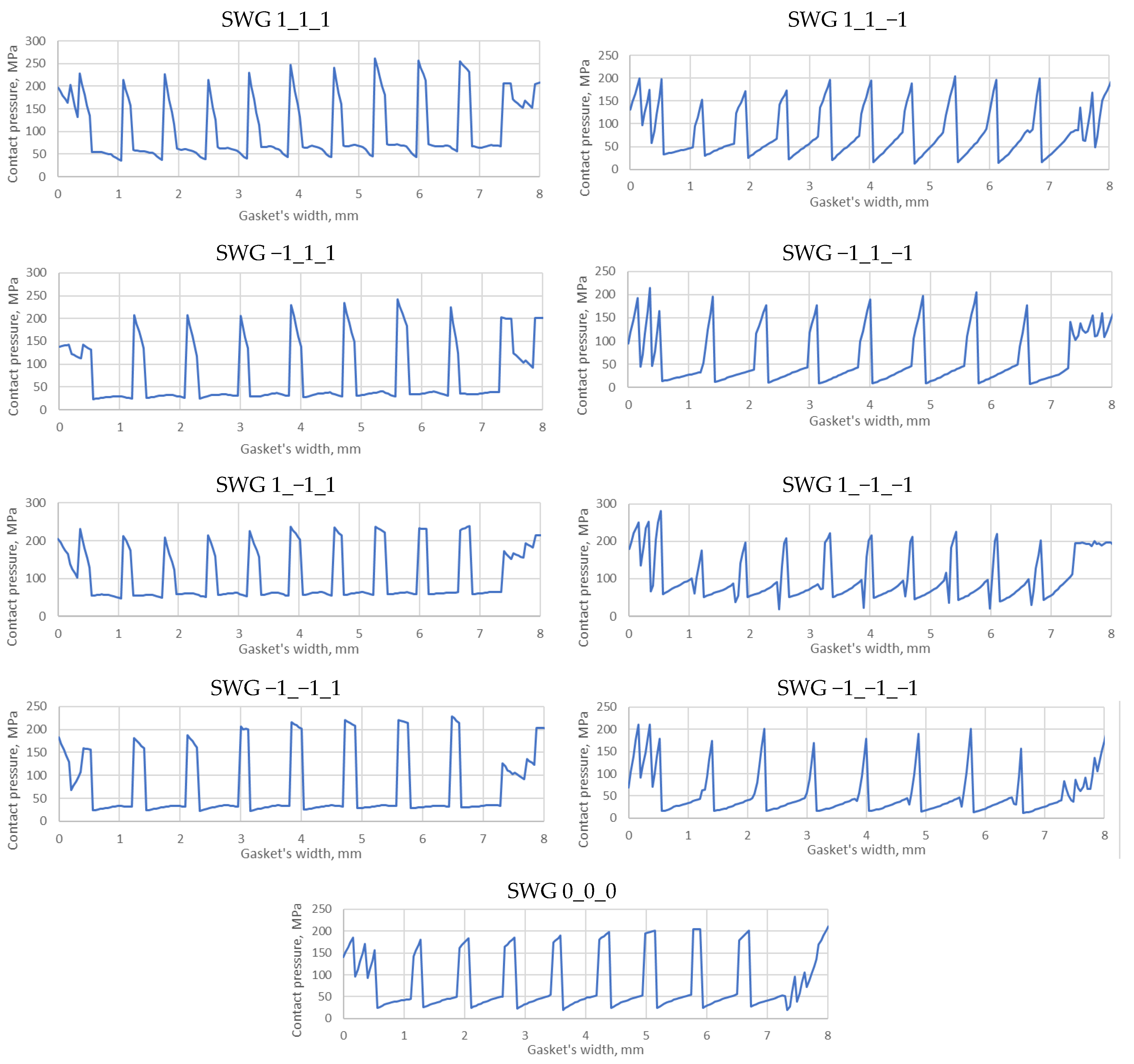
3. Results
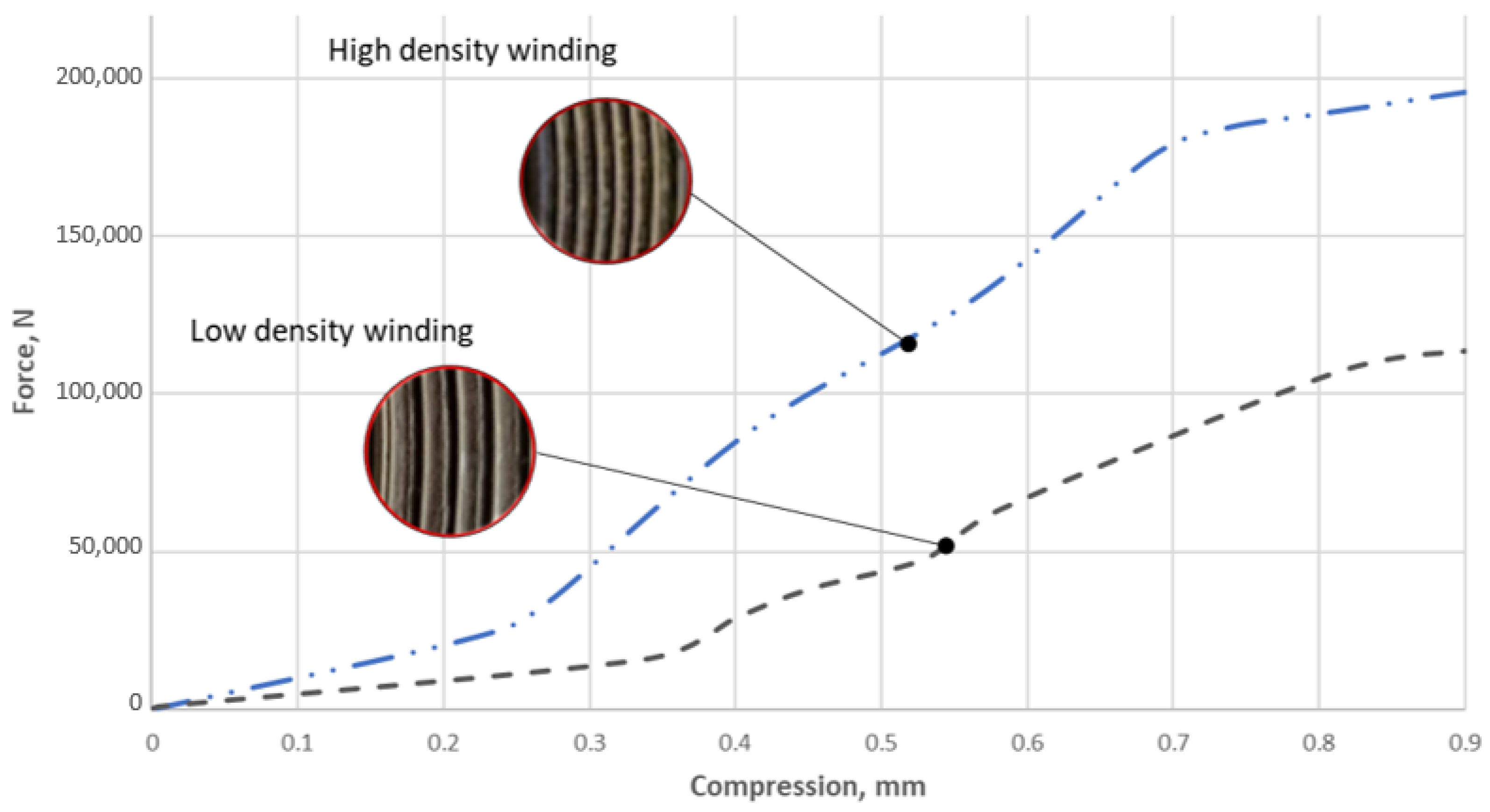
3.1. Evaluation of the Effect of the Winding Density of the Spiral Gasket on Its Axial Stiffness
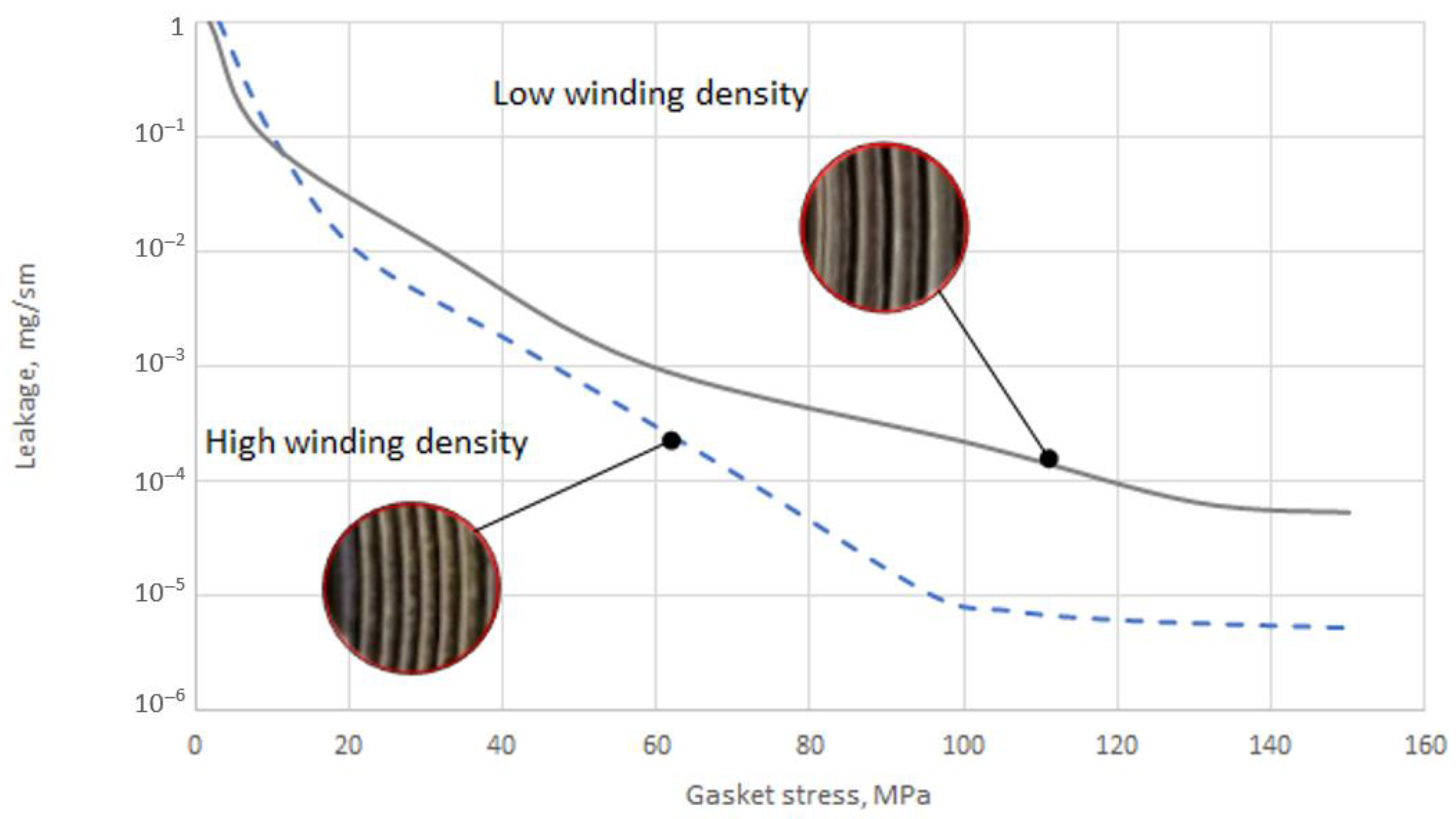
3.2. Evaluation of the Influence of the Winding Density of the Spiral Gasket on Its Tightness
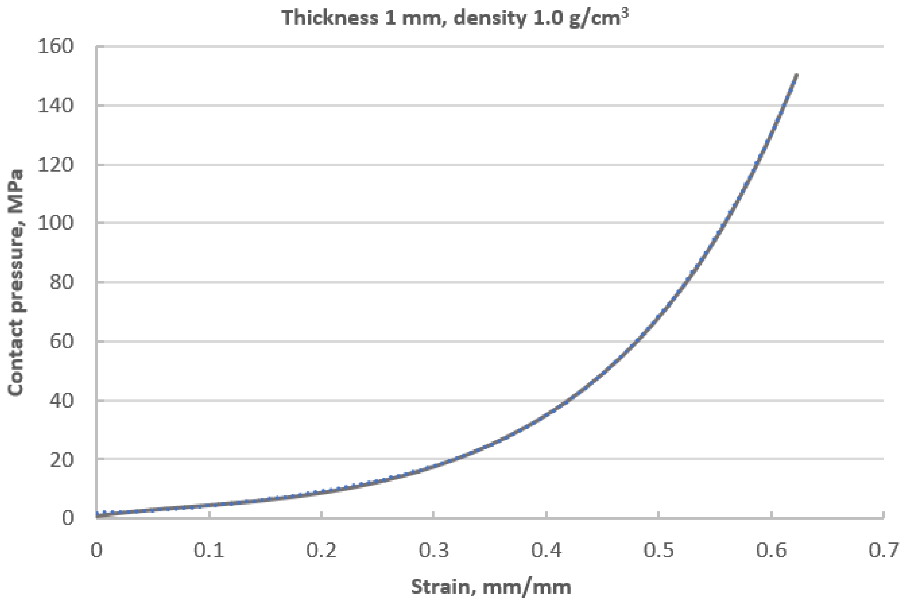
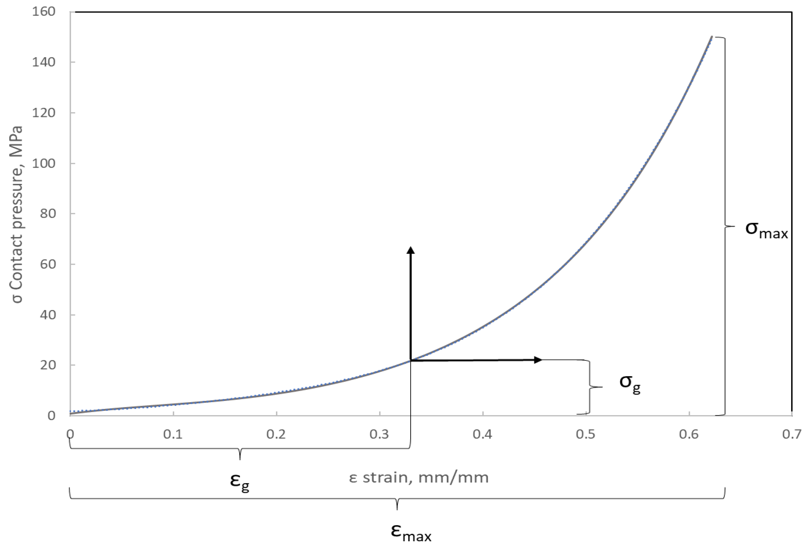
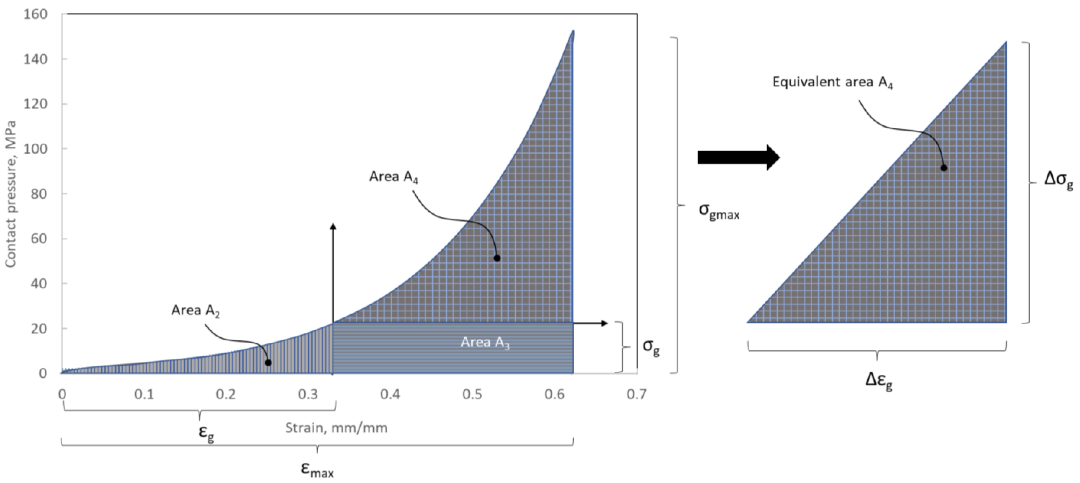
3.3. Elastic–Plastic Properties of the Filler
3.4. Model of the Material of the Filler
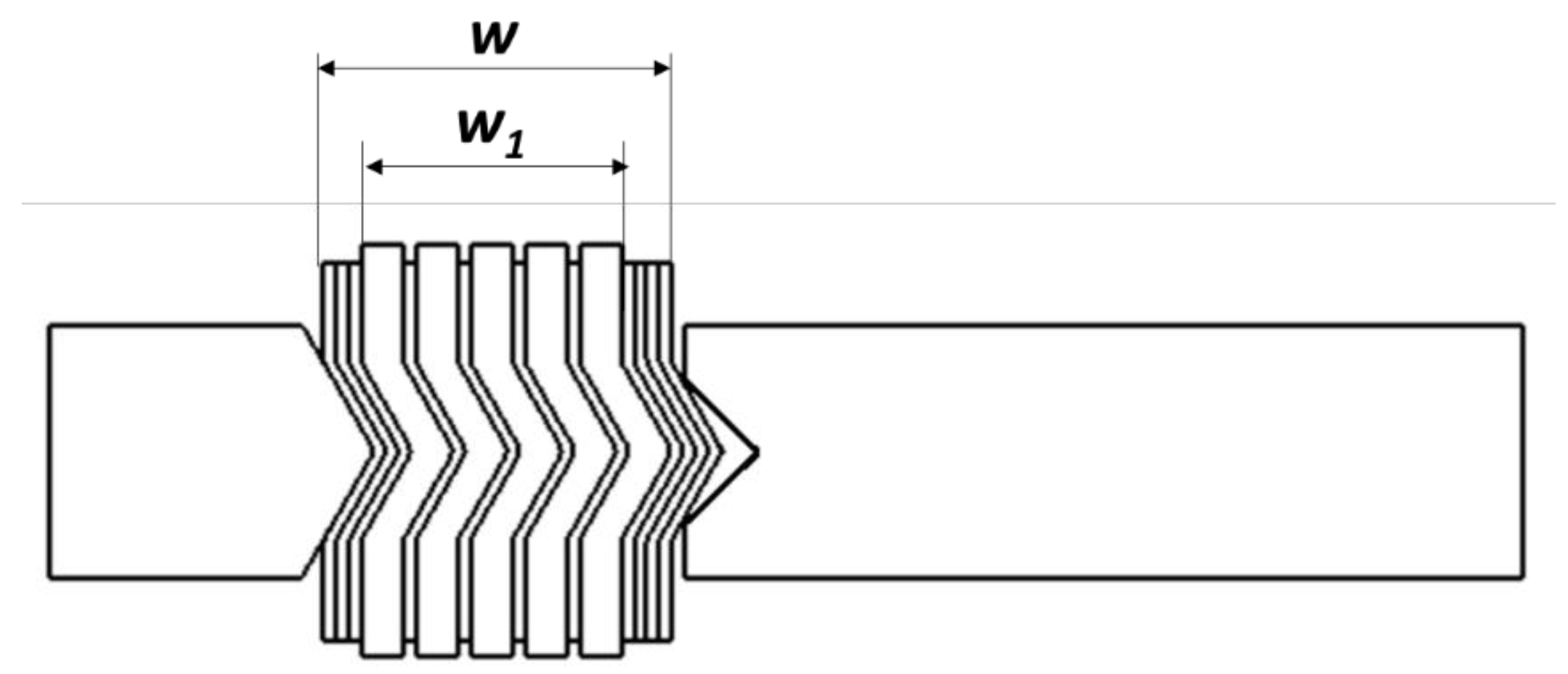
- w—total width of the spiral part of the gasket;
- w1—effective width of the spiral part of the gasket (without taking into account the beginning and end windings of the metal strip);
- ts—metal strip thickness;
- na—total number of the beginning and end windings of the metal strip.
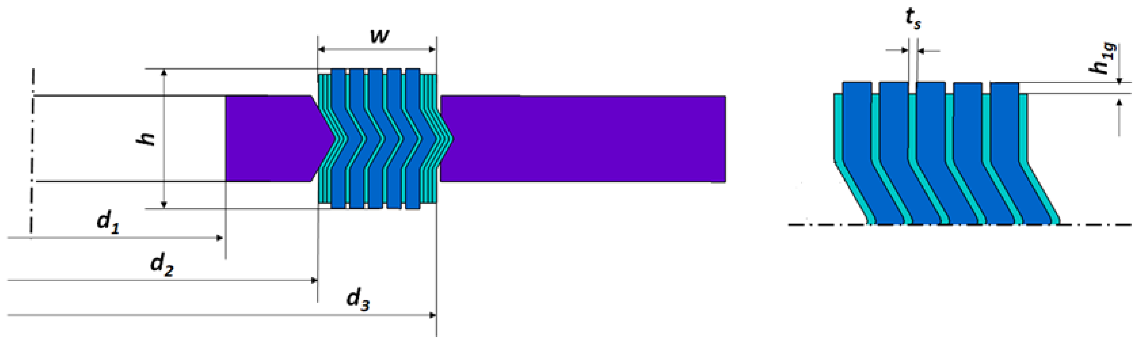
- tg—current thickness of the filler strip;
- ng—total number of windings of the filler.
- tg0—nominal thickness of the filler strip (thickness before being wound into a spiral);
- Δtg—compression of the filler.
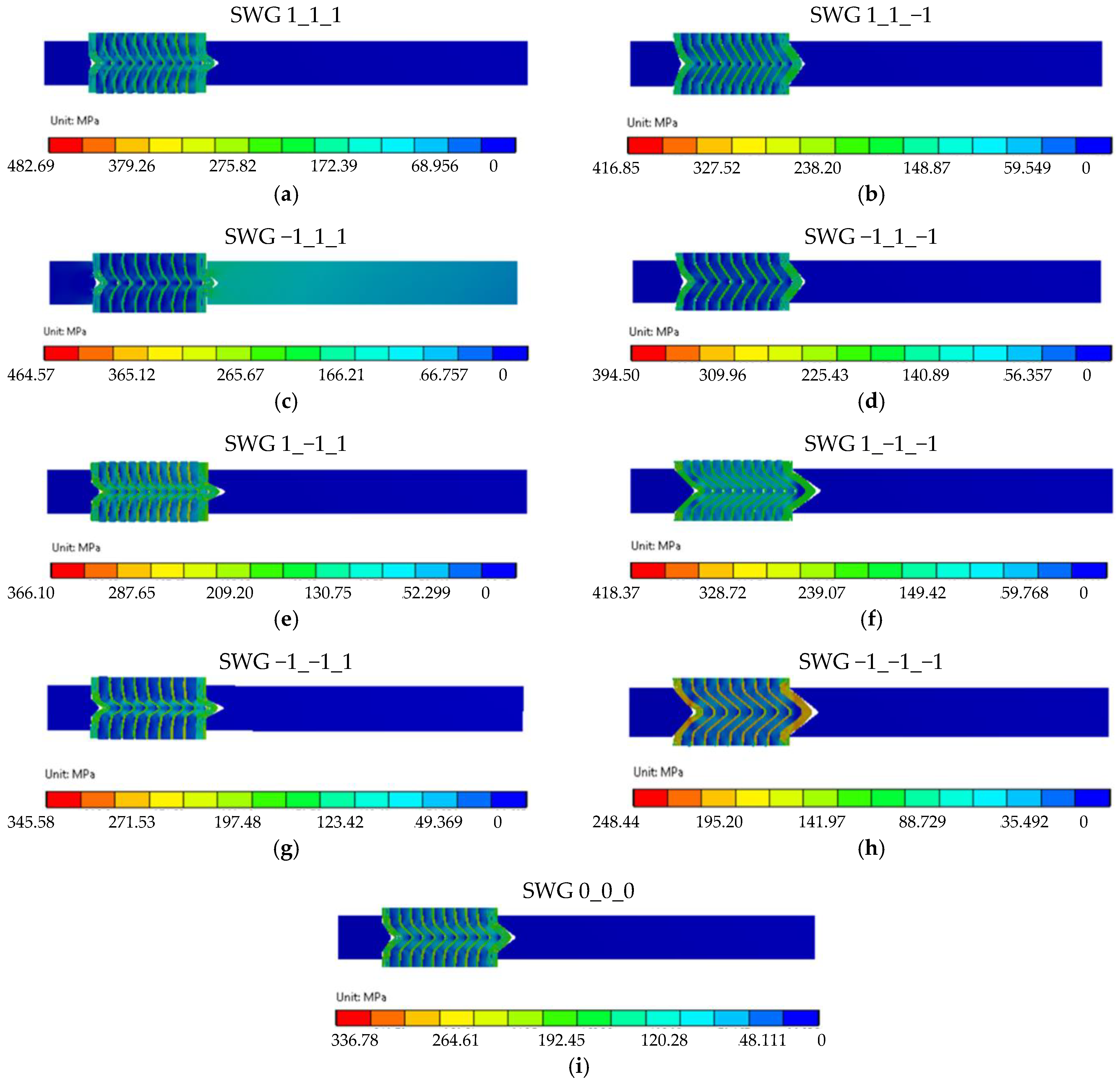
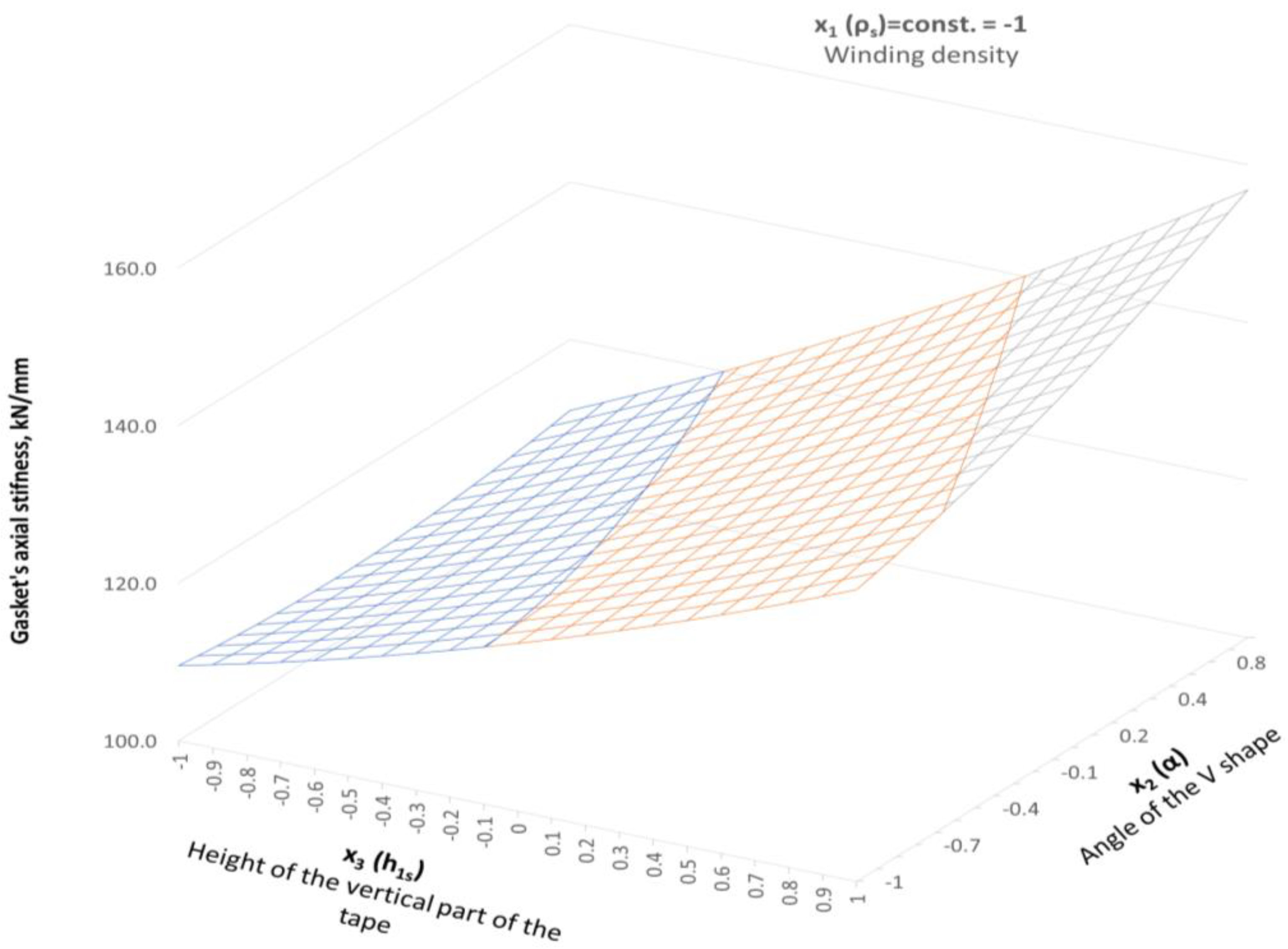
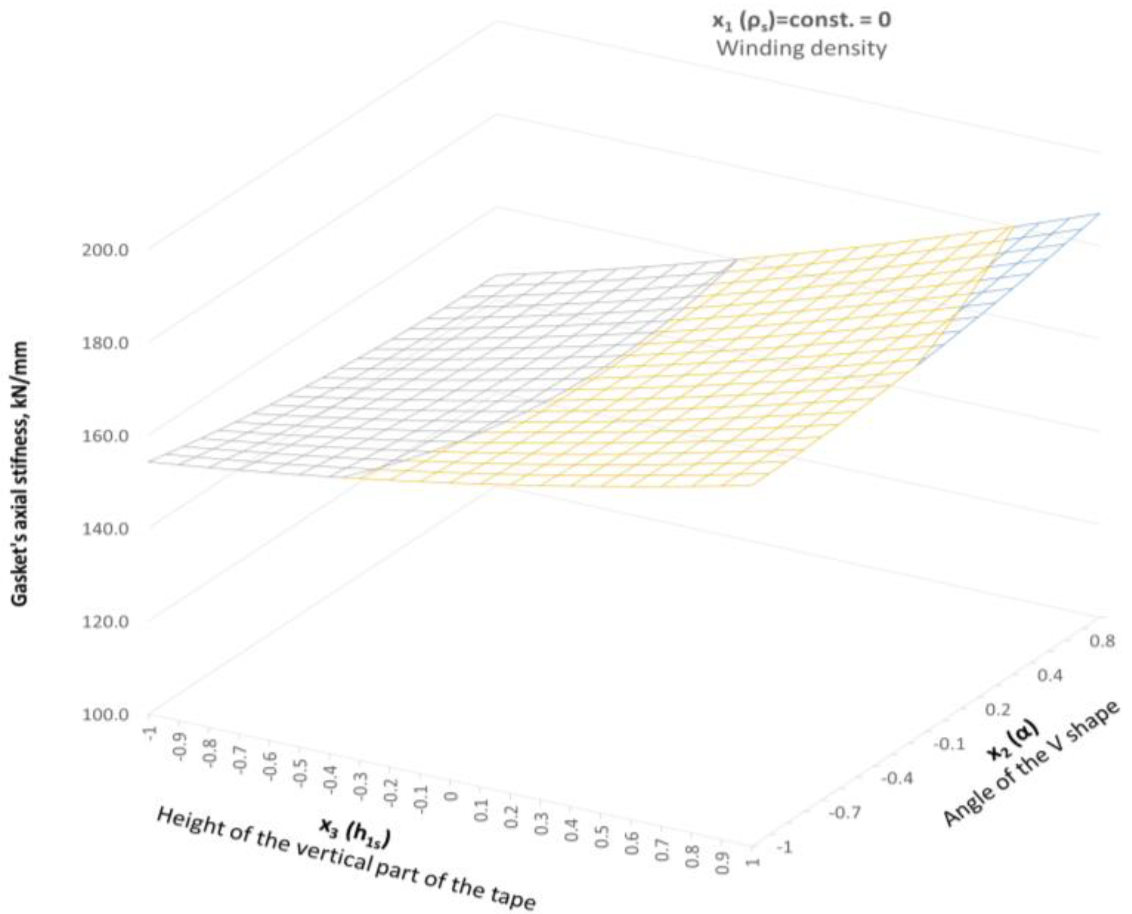
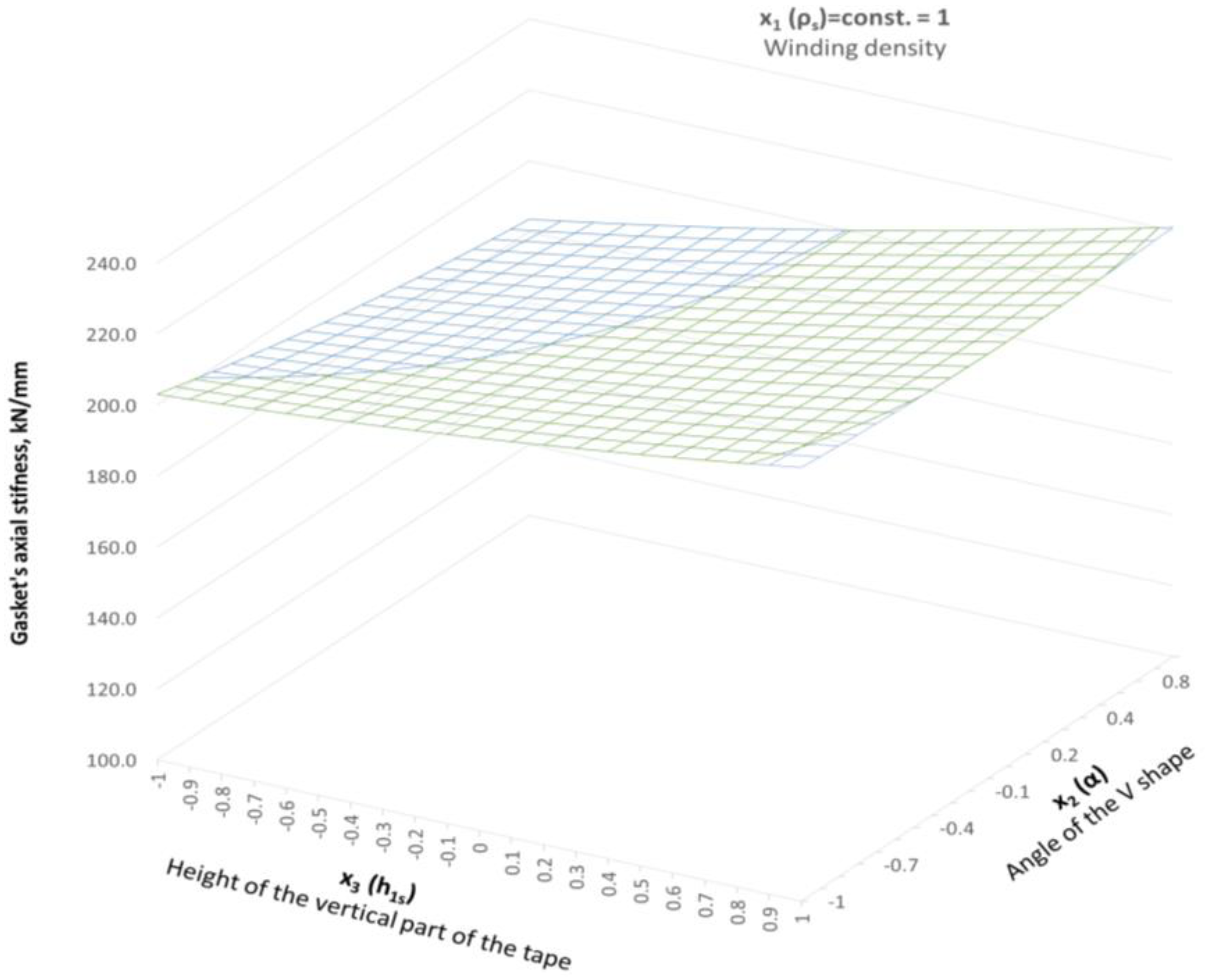
3.5. Results of the Numerical Calculations
3.6. Analytical Mapping of the Gasket Stiffness
- —arithmetic mean of the gasket axial stiffness;
- q—number of decisive parameters (q = 3);
- —axial stiffness of the gasket obtained from the tests.
- —response function (axial stiffness of the gasket);
- N—number of the tests (design variants N = 11);
- k—number of regression coefficients (k = 10).
4. Discussion
5. Conclusions
- 1.
- An increase in the winding density leads to a greater axial stiffness of the gasket and, thus, a reduction in its compressibility;
- 2.
- As the winding density increases, the gasket tightness increases, and this increase in high contact pressure can be up to an order of magnitude greater compared to a gasket with a lower winding density;
- 3.
- The greater the degree of densification of the winding, the greater the stresses created in all elements of the gasket (metal guide rings, steel and filler strips);
- 4.
- As the vertical part of the metal strip (parameter h1s) increases, the axial stiffness of the gasket decreases;
- 5.
- As the angle of inclination of the central part of the winding cross-section increases, the axial stiffness of the gasket increases.
Author Contributions
Funding
Institutional Review Board Statement
Informed Consent Statement
Data Availability Statement
Conflicts of Interest
Nomenclature
| Symbol | Definition | Unit |
| A1, A2, A3, A4 | Characteristic areas | mm2 |
| b0, bi, bii, bij | Polynomial coefficients | - |
| d1, d2, d3 | Characteristic gasket diameters | mm |
| E | Young’s modulus | MPa |
| F | F-Sendecor function | - |
| h | Gasket height | mm |
| h1g | Height of the part of the filler strip protruding above the metal strip | mm |
| h1s | Height of the vertical part of the metal strip | mm |
| k | Number of regression coefficients | - |
| na | Total number of the beginning and end windings of the metal strip | - |
| ng | Total number of winding of the filler | - |
| N | Number of the tests | - |
| q | Number of decisive parameters | - |
| Rp0.2 | Yield strength | MPa |
| Variance of the gasket axial stiffness experiment | kN/mm | |
| Variance of the model compliance | kN/mm | |
| ts | Metal strip thickness | mm |
| tg | Current thickness of the filler strip | mm |
| tg0 | Nominal thickness of the filler strip | mm |
| w | Total width of the spiral part of the gasket | mm |
| w1 | Effective width of the spiral part of the gasket | mm |
| Response function (axial stiffness of the gasket) | kN/mm | |
| yn | Axial stiffness of the gasket obtained from the tests | kN/mm |
| Arithmetic mean of the gasket axial stiffness | kN/mm | |
| α | Angle of inclination of the central part of the spiral section | ° |
| β | Level of significance | - |
| Δtg | Compression of the filler | mm |
| ε, εg, εmax | Strain, current strain of the filler, maximum strain of the filler | - |
| ν | Poisson’s ratio | - |
| ν1, ν2 | Numbers of degrees of freedom | - |
| ρs | Winding density of the spiral gasket | turns/mm |
| σ, σg, σmax | Stress, current stress of the filler, maximum stress of the filler | MPa |
| ϕ | Diameter | mm |
References
- Huebner, M. Material Selection for Mechanical Seals. Turbomachinery Laboratories, Texas A&M University, College Station, Texas, USA. Available online: https://oaktrust.library.tamu.edu/bitstream/handle/1969.1/163962/15.pdf?sequence=1&isAllowed=y (accessed on 6 September 2023).
- Bausman, A.; Waterland, J.; Reid, D. New Leakage Requirements for ASME B16.20 and Current Generation Spiral Wound Gaskets. In Proceedings of the ASME 2019 Pressure Vessels & Piping Conference, San Antonio, TX, USA, 14–19 July 2019; Volume 2. [Google Scholar]
- Venturini, A.; Papa, F.; Utili, M. Preliminary experimental quantification of helium leakages from flanged connections at HCPB TBS operative conditions. Energies 2023, 16, 5519. [Google Scholar] [CrossRef]
- Adamczak, S.; Zmarzły, P.; Janecki, D. Theoretical and practical investigations of V-block waviness measurement of cylindrical parts. Metrol. Meas. Syst. 2015, 22, 181–192. [Google Scholar] [CrossRef]
- Nelson, N.R.; Siva Prasad, N.; Sekhar, A.S. Structural integrity and sealing behaviour of bolted flange joint: A state of art review. Int. J. Press. Vessel. Pip. 2023, 204, 104975. [Google Scholar] [CrossRef]
- Zhong, J.; Liu, D.; Zhou, T.; Guan, K. Failure analysis of outer ring of spiral wound gasket. Eng. Fail. Anal. 2020, 117, 104962. [Google Scholar] [CrossRef]
- Attoui, H.; Bouzid, A.-H.; Waterland, J.A. Buckling and Lateral Pressure in Spiral Wound Gasket. In Proceedings of the ASME 2014 Pressure Vessels & Piping Conference, Anaheim, CA, USA, 20–24 July 2014; Volume 2. [Google Scholar]
- Jenco, J.M.; Hunt, E.S. Generic issues effecting spiral-wound gasket performance. Int. J. Press. Vessel. Pip. 2000, 77, 825–830. [Google Scholar] [CrossRef]
- Waterland III, A.F.J.; Bouzid, A.-H. Analysis of the Compression Behavior of Spiral Wound Gaskets. In Proceedings of the ASME 2009 Pressure Vessels and Piping Conference, Prague, Czech Republic, 26–30 July 2009; Volume 2, pp. 89–97, Computer Applications/Technology and Bolted Joints. [Google Scholar]
- ASME B16.20, 2017; Metallic Gaskets for Pipe Flanges. The American Society of Mechanical Engineers: New York, NY, USA, 2017.
- PN-EN 1514-2, 2021-06; Flanges and Their Joints, Gaskets for PN-Designated Flanges, Part 2: Spiral Wound Gaskets for Use with Steel Flanges. Polish Committee for Standardization: Warsaw, Poland, 2021.
- Adamek, K.; Jaszak, P. Design method of enhancing the tightness of a spiral wound gasket with PTFE filling. J. Braz. Soc. Mech. Sci. Eng. 2023, 45, 332. [Google Scholar] [CrossRef]
- Veiga, J.C.; Cipolatti, C.F.; Kavanagh, N.; Reeves, D. The Influence of Winding Density in the Sealing Behavior of Spiral Wound Gaskets. In Proceedings of the ASME 2011 Pressure Vessel and Piping Conference, Baltimore, MD, USA, 17–21 July 2011; Volume 3, pp. 103–111, Design and Analysis. [Google Scholar]
- Veiga, J.C.; da Silva, G.M.; Kavanagh, N. Factors that Influence the Sealing Behavior of Spiral Wound Gasket. In Proceedings of the ASME 2013 Pressure Vessel and Piping Conference, Paris, France, 14–18 July 2013; Volume 2. [Google Scholar]
- Aljuboury, M.; Rizvi, M.J.; Grove, S.; Cullen, R. A numerical investigation of the sealing performance and the strength of a raised face metallic bolted flange joint. Int. J. Press. Vessel. Pip. 2021, 189, 104255. [Google Scholar] [CrossRef]
- Hamilton, S.; Baulch, J.; Veiga, J. ASME B16.20 Spiral Wound Gaskets Performance Testing. In Proceedings of the ASME 2017 Pressure Vessels and Piping Conference, Waikoloa, HI, USA, 16–20 July 2017; Volume 3A. [Google Scholar]
- Zhang, Z.; Wang, D.; Guo, Y. Fretting friction and wear behaviors of spiral wound gasket (SWG) sealing surface. Tribol. Int. 2019, 133, 236–245. [Google Scholar] [CrossRef]
- Grzejda, R. FE-modelling of a contact layer between elements joined in preloaded bolted connections for the operational condition. Adv. Sci. Technol. Res. J. 2014, 8, 9–23. [Google Scholar] [CrossRef]
- Grzejda, R. New Method of Modelling Nonlinear Multi-Bolted Systems. In Advances in Mechanics: Theoretical, Computational and Interdisciplinary Issues, 1st ed.; Kleiber, M., Burczyński, T., Wilde, K., Gorski, J., Winkelmann, K., Smakosz, Ł., Eds.; CRC Press: Leiden, The Netherlands, 2016; pp. 213–216. [Google Scholar]
- Grzejda, R.; Warzecha, M.; Urbanowicz, K. Determination of pretension in bolts for structural health monitoring of multi-bolted connection: FEM approach. Lubricants 2022, 10, 75. [Google Scholar] [CrossRef]
- Łukaszewicz, A.; Miatluk, K. Reverse engineering approach for object with free-form surfaces using standard surface-solid parametric CAD system. Solid State Phenom. 2009, 147–149, 706–711. [Google Scholar] [CrossRef]
- Łukaszewicz, A.; Panas, K.; Szczebiot, R. Design Process of Technological Line to Vegetables Packaging using CAx Tools. In Proceedings of the 17th International Scientific Conference on Engineering for Rural Development, Jelgava, Latvia, 23–25 May 2018; pp. 871–876. [Google Scholar]
- Murali Krishna, M.; Shunmugam, M.S.; Siva Prasad, N. A study on the sealing performance of bolted flange joints with gaskets using finite element analysis. Int. J. Press. Vessel. Pip. 2007, 84, 349–357. [Google Scholar] [CrossRef]
- Jaszak, P. Adaptation of a highly compressible elastomeric material model to simulate compressed expanded graphite and its application in the optimization of a graphite-metallic structure. J. Braz. Soc. Mech. Sci. Eng. 2020, 42, 224. [Google Scholar] [CrossRef]
- Jaszak, P. Modeling of the elastic properties of compressed expanded graphite—A material used in spiral wound gaskets. Int. J. Press. Vessel. Pip. 2020, 187, 104158. [Google Scholar] [CrossRef]
- Nelson, N.R. Effective modeling of spiral wound gasket with graphite filler in gasketed flange joint subjected to bending loads. Mater. Today Proc. 2021, 44, 2199–2204. [Google Scholar] [CrossRef]
- Abid, M.; Hussain, S. Bolt preload scatter and relaxation behavior during tightening a 4 in-900# flange joint with spiral wound gasket. Proc. Inst. Mech. Eng. Part E J. Process Mech. Eng. 2008, 222, 123–134. [Google Scholar]
- Veiga, J.C.; Cipolatti, C.F.; Reeves, D. Spiral Wound Versus Flexible Graphite Faced Serrated Metal Pipe Flange Gaskets in Thermal Cycling and Pressure Comparative Testing. In Proceedings of the ASME 2010 Pressure Vessels and Piping Division/K-PVP Conference, Bellevue, WA, USA, 18–22 July 2010; Volume 3, pp. 157–165. [Google Scholar]
- Nelson, N.R. Numerical evaluation of effective compression behaviour of spiral wound gasket under loading and unloading. Adv. Mater. Process Technol. 2022, in press. [CrossRef]
- Mathan, G.; Siva Prasad, N. Evaluation of effective material properties of spiral wound gasket through homogenization. Int. J. Press. Vessel. Pip. 2010, 87, 704–713. [Google Scholar] [CrossRef]
- Attoui, H.; Bouzid, A.-H. On the Equivalent Mechanical Properties of Spiral Wound Gaskets. In Proceedings of the ASME 2016 Pressure Vessels and Piping Conference, Vancouver, BC, Canada, 17–21 July 2016; Volume 2. [Google Scholar]
- ASME, BPVC, 2019; Boiler and Pressure Vessel Code. The American Society of Mechanical Engineers: New York, NY, USA, 2019.
- Nelson, N.R.; Siva Prasad, N. Sealing behavior of twin gasketed flange joints. Int. J. Press. Vessel. Pip. 2016, 138, 45–50. [Google Scholar] [CrossRef]
- Ferreira, S.L.C.; Bruns, R.E.; Ferreira, H.S.; Matos, G.D.; David, J.M.; Brandão, G.C.; da Silva, E.G.P.; Portugal, L.A.; dos Reis, P.S.; Souza, A.S.; et al. Box-Behnken design: An alternative for the optimization of analytical methods. Anal. Chim. Acta 2007, 597, 179–186. [Google Scholar] [CrossRef]
- Devesa-Rey, R.; Arce, E.; Cartelle, A.; Suárez-García, A. Use of Plackett–Burman and Box–Behnken designs to optimize bioelectricity production from winery residues. Water 2023, 15, 3051. [Google Scholar] [CrossRef]
- Liovic, P.; Šutalo, I.D.; Marasco, F. Stress analysis of a centrally fractured rib fixated by an intramedullary screw. Comput. Methods Biomech. Biomed. Eng. 2014, 17, 944–957. [Google Scholar] [CrossRef] [PubMed]
- Hemanth, A.N.; Sudharshan, N. Fatigue analysis and optimization of floor beam in aircraft using ANSYS Workbench. Int. Res. J. Mod. Eng. Technol. Sci. 2020, 2, 877–885. [Google Scholar]
- Wang, J.; He, Q.; Pei, Y.; Shi, Y. Effect of angle of V-type steel belt on performance of spiral wound gasket. Appl. Mech. Mater. 2014, 501–504, 717–721. [Google Scholar]
- Kumar, A.; Singh, B. Streamlining of process parameters for PCM of Inconel using response surface methodology. Int. J. Eng. Res. Manag. 2021, 41, 112–137. [Google Scholar]
- Létal, T. Estimating leak rates of circular gaskets under nonuniform contact pressures using EN 13555 test data. Int. J. Press. Vessel. Pip. 2022, 200, 104809. [Google Scholar] [CrossRef]


| Independent Real Variables | ||
|---|---|---|
| Winding Density of the Spiral Gasket ρs, turns/mm | Angle of Inclination α, Degrees | Height of the Vertical Part of the Metal Strip h1s, mm |
| 1.18 | 45 | 0.8 |
| 1.46 | 70 | 1.6 |
| 1.32 | 57.5 | 1.2 |
| 0.14 | 12.5 | 0.4 |
| Independent coded variables | ||
| x1 | x2 | x3 |
| −1 | −1 | −1 |
| 1 | 1 | 1 |
| 0 | 0 | 0 |
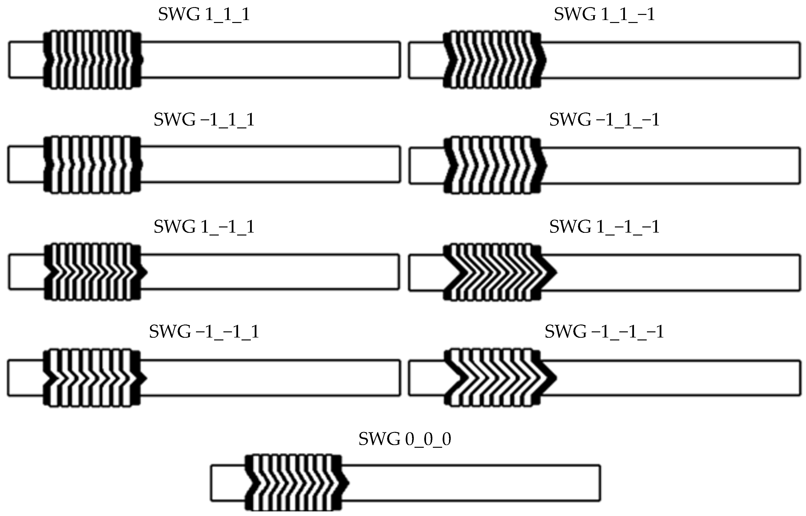
| Geometric Model Variant | Test No. | Design Matrix | ||||||
|---|---|---|---|---|---|---|---|---|
| x0 | x1 | x2 | x3 | x1x2 | x1x3 | x2x3 | ||
| SWG 1_1_1 | 1 | 1 | 1 | 1 | 1 | 1 | 1 | 1 |
| SWG −1_1_1 | 2 | 1 | −1 | 1 | 1 | −1 | −1 | 1 |
| SWG 1_−1_1 | 3 | 1 | 1 | −1 | 1 | −1 | 1 | −1 |
| SWG −1_−1_1 | 4 | 1 | −1 | −1 | 1 | 1 | −1 | −1 |
| SWG 1_1_−1 | 5 | 1 | 1 | 1 | −1 | 1 | −1 | −1 |
| SWG −1_1_−1 | 6 | 1 | −1 | 1 | −1 | −1 | 1 | −1 |
| SWG 1_−1_−1 | 7 | 1 | 1 | −1 | −1 | −1 | −1 | 1 |
| SWG −1_−1_−1 | 8 | 1 | −1 | −1 | −1 | 1 | 1 | 1 |
| SWG 0_0_0 | 9 | 1 | 0 | 0 | 0 | 0 | 0 | 0 |
| Winding Density of the Spiral Gasket ρs, Turns/mm | Current Thickness of the Filler tg, mm | Young’s Modulus E(tg), MPa |
|---|---|---|
| 1.18 | 0.69 | 290.9 |
| 1.32 | 0.59 | 420.5 |
| 1.46 | 0.52 | 544.9 |
| Experiment No. | Geometric Model Variant | FEM, yn | Response Function, |
|---|---|---|---|
| 1 | SWG 1_1_1 | 225.3 | 221.0 |
| 2 | SWG −1_1_1 | 148.0 | 156.8 |
| 3 | SWG 1_−1_1 | 213.3 | 222.1 |
| 4 | SWG −1_−1_1 | 141.3 | 137.0 |
| 5 | SWG 1_1_−1 | 174.7 | 183.5 |
| 6 | SWG −1_1_−1 | 115.3 | 111.0 |
| 7 | SWG 1_−1_−1 | 207.3 | 203.0 |
| 8 | SWG −1_−1_−1 | 100.7 | 109.5 |
| 9 | SWG 0_0_0 | 162.0 | 162.0 |
| 10 | SWG 0_0_0 | 178.2 | 162.0 |
| 11 | SWG 0_0_0 | 145.8 | 162.0 |
Disclaimer/Publisher’s Note: The statements, opinions and data contained in all publications are solely those of the individual author(s) and contributor(s) and not of MDPI and/or the editor(s). MDPI and/or the editor(s) disclaim responsibility for any injury to people or property resulting from any ideas, methods, instructions or products referred to in the content. |
© 2023 by the authors. Licensee MDPI, Basel, Switzerland. This article is an open access article distributed under the terms and conditions of the Creative Commons Attribution (CC BY) license (https://creativecommons.org/licenses/by/4.0/).
Share and Cite
Jaszak, P.; Grzejda, R.; Kluczyński, J.; Zmarzły, P. Basic Design Parameters Influencing on Axial Stiffness of the Spiral Wound Gasket. Materials 2023, 16, 6209. https://doi.org/10.3390/ma16186209
Jaszak P, Grzejda R, Kluczyński J, Zmarzły P. Basic Design Parameters Influencing on Axial Stiffness of the Spiral Wound Gasket. Materials. 2023; 16(18):6209. https://doi.org/10.3390/ma16186209
Chicago/Turabian StyleJaszak, Przemysław, Rafał Grzejda, Janusz Kluczyński, and Paweł Zmarzły. 2023. "Basic Design Parameters Influencing on Axial Stiffness of the Spiral Wound Gasket" Materials 16, no. 18: 6209. https://doi.org/10.3390/ma16186209