
Research Progress of ODS FeCrAl Alloys–A Review of Composition Design


Abstract
:1. Introduction
- (1)
- High thermal conductivity, low coefficient of thermal expansion;
- (2)
- Small neutron absorption cross-section, low induced radioactivity, short radioactive half-life, and good radiation resistance;
- (3)
- Good compatibility between the fuel and the coolant (strong corrosion resistance);
- (4)
- High strength, good plasticity, and toughness at elevated temperatures.
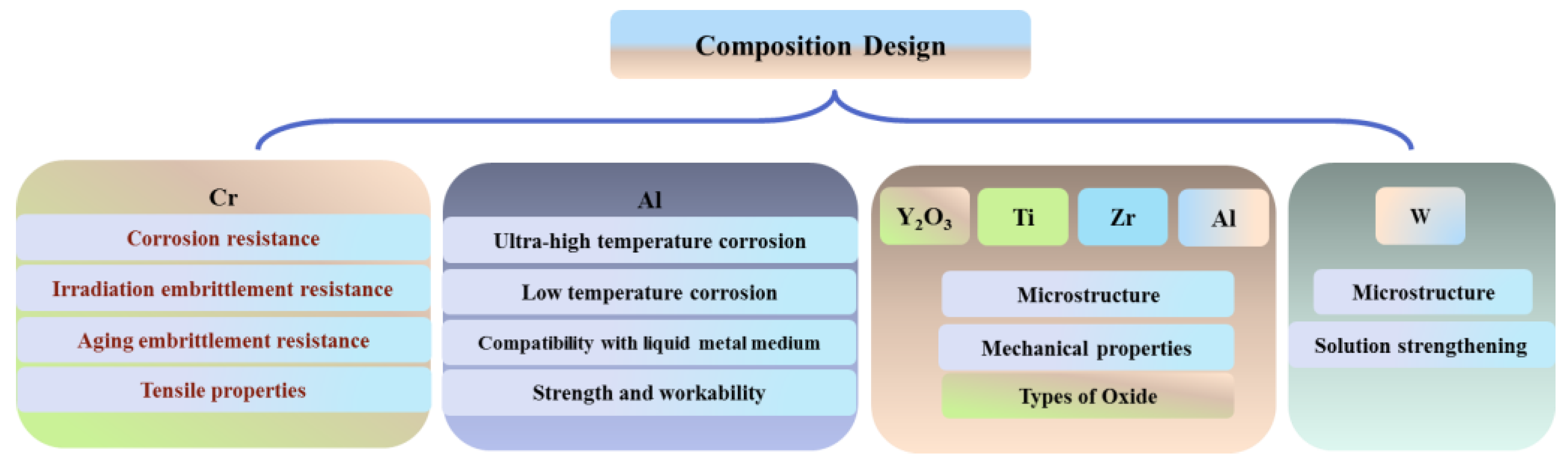
2. Effect of Chemical Elements on the Properties and Microstructure of ODS FeCrAl
2.1. The Influence of Cr
2.2. The Influence of Al
2.2.1. Ultra-High Temperature Corrosion (T > 1000 °C)
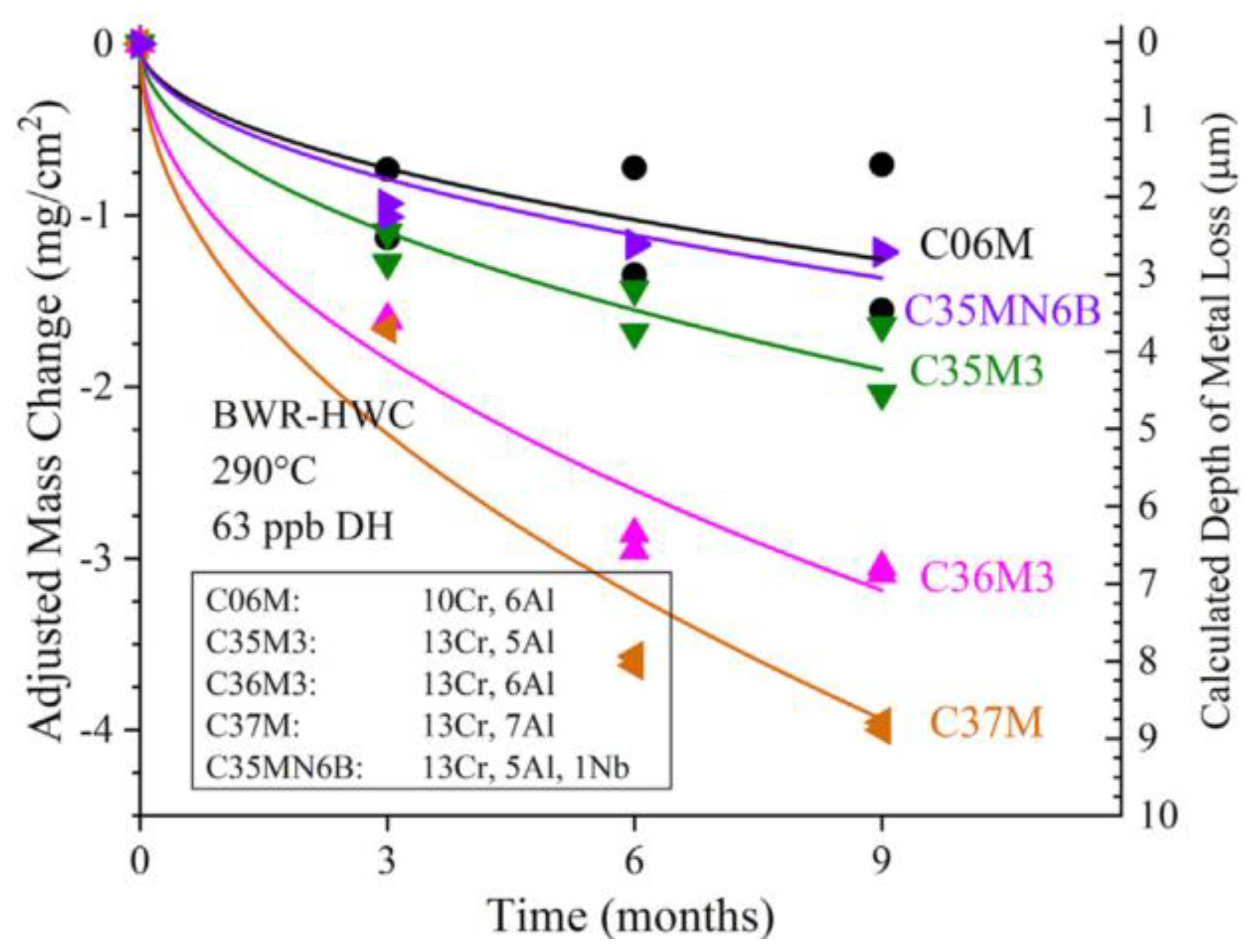
2.2.2. Low Temperature Corrosion in a Light Water Nuclear Reactor (T < 1000 °C)
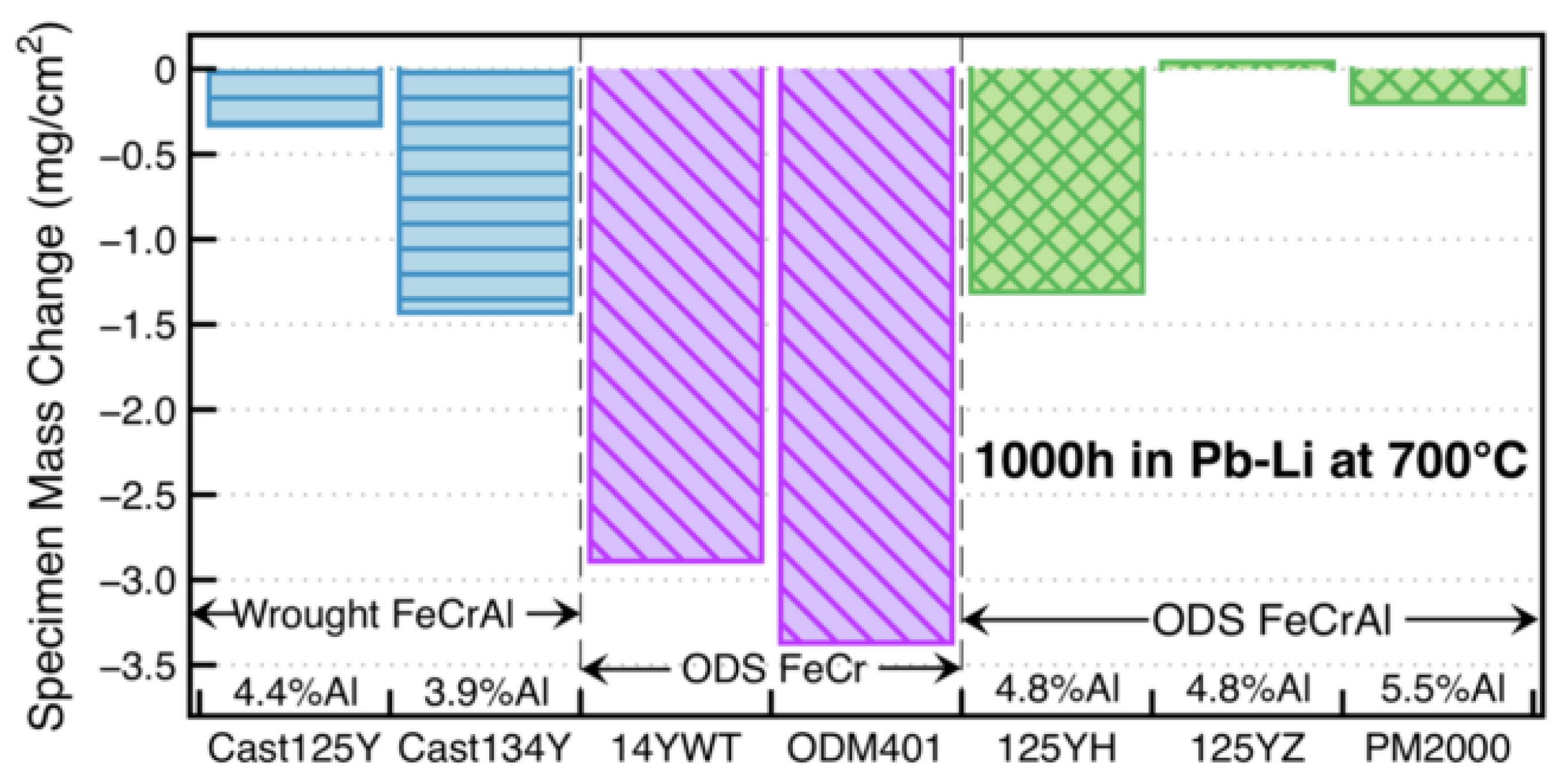
2.2.3. Compatibility with Liquid Metal Medium
2.2.4. Effect of Al on Strength and Workability
3. Influence of Elements on Microstructure and Properties
3.1. Y2O3
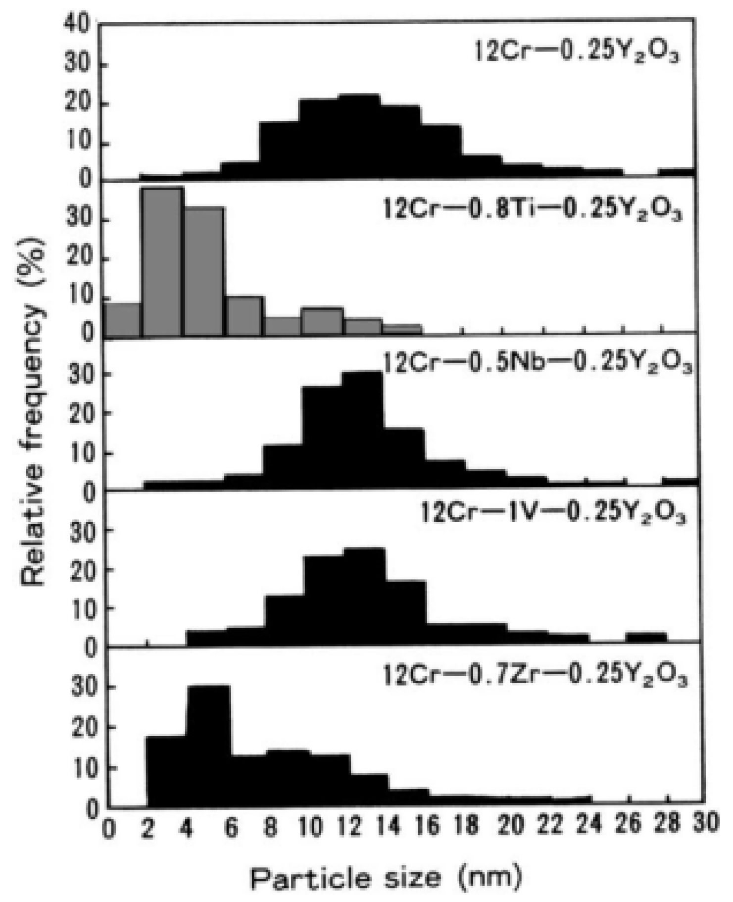
3.2. Ti
3.3. Al
3.4. Zr
3.5. W
4. Conclusions
- (1)
- The effects of Cr and Al content in the ODS FeCrAl alloy on the corrosion behavior, radiation, thermal stability of the matrix, and processing feasibility were summarized, and the range of reasonable design content of the two elements above was stated in detail;
- (2)
- The role of oxide-forming elements, i.e., Y (Y2O3), Ti, Al, Zr, and solid solution strengthening elements, i.e., W, in ODS FeCrAl alloy and the design basis for their reasonable content were concluded;
- (3)
- The important effects of different alloy elements on the type and size distribution of the oxide particles were introduced;
- (4)
- The density functional theory-based calculation of formation and reaction enthalpies to examine the relative stability of a large number of likely oxide phases of typical ODS FeCrAl alloys based on the Fe–Cr–Al–Zr–Y–O system, with the Fe–Cr–Al–Zr–Ti–Y–O system still to be performed;
- (5)
- In the as-prepared ODS FeCrAl alloy, several populations of nano-oxides can precipitate simultaneously. However, in the process of preparing cladding tubes, due to the generation of a large number of dislocations, these oxide-forming elements may diffuse along the dislocation pipes due to the interaction between the oxides and dislocations. During this process, oxides may undergo the phenomenon of “dissolution–precipitation–re-dissolution–re-precipitation”. These types of oxides may even undergo chemical reactions to generate non-equilibrium products. These possible changes in the microstructure caused by the competition between the various alloying elements, as well as their impacts on the service performance of the ODS FeCrAl alloy, should be paid attention to in future research;
- (6)
- Based on the review, several other aspects of the ODS FeCrAl alloy will be reviewed in another paper, such as the effects of heat solidification parameters on the microstructure and mechanical properties; and a comparison of the high temperature stability and irradiation stability of typical oxides, i.e., Y–Ti–O, Y–Al–O, and Y–Zr–O phases; and a summary of the microstructure evolution of ODS FeCrAl alloy under plastic deformation. These will contribute to a comprehensive understanding of the entire alloy development process.
Author Contributions
Funding
Institutional Review Board Statement
Informed Consent Statement
Data Availability Statement
Acknowledgments
Conflicts of Interest
References
- Zinkle, S.J.; Terrani, K.A.; Gehin, J.C.; Ott, L.J.; Snead, L.L. Accident tolerant fuels for LWRs: A perspective. J. Nucl. Mater. 2014, 448, 374–379. [Google Scholar] [CrossRef]
- Department of Energy. Development of Light Water Reactor Fuels with Enhanced Accident Tolerance. In Report to Congress; Department of Energy: Washington, DC, USA, 2015. [Google Scholar]
- Rebak, R.B.; Andresen, P.L.; Kim, Y.J.; Dolley, E.J. Characterization of Advanced Steels as Accident Tolerant Fuel Cladding for Light Water Reactors; Technical Report IAEA-TECDOC-1797; International Atomic Energy Agency: Vienna, Austria, 2014. [Google Scholar]
- Rebak, R.B. Characterization of Advanced Steels as Accident Tolerant Cladding for Light Water Reactor Nuclear Fuel. In Proceedings of the ASME 2015 Pressure Vessels and Piping Conference, Boston, MA, USA, 19–23 July 2015. [Google Scholar]
- Rebak, R.B. Alloy selection for accident tolerant fuel cladding in commercial light water reactors. Metall. Mater. Trans. E 2015, 2, 197–207. [Google Scholar] [CrossRef]
- Rebak, R.B.; Terrani, K.A.; Fawcett, R.M. FeCrAl Alloys for Accident Tolerant Fuel Cladding in Light Water Reactors. In Proceedings of the ASME 2016 Pressure Vessel & Piping Conference, Vancouver, BC, Canada, 17–21 July 2016. [Google Scholar]
- Rebak, R.B.; Larsen, M.; Kim, Y.J. Characterization of oxides formed on iron-chromium-aluminum alloy in simulated light water reactor environments. Corros. Rev. 2017, 35, 177–188. [Google Scholar] [CrossRef]
- Rebak, R.B.; Terrani, K.A.; Gassmann, W.P.; Williams, J.B.; Ledford, K.L. Improving nuclear power plant safety with FeCrAl alloy fuel cladding. MRS Adv. 2017, 2, 1217–1224. [Google Scholar] [CrossRef]
- Dolley, E.J.; Schuster, M.; Crawford, C.; Rebak, R.B. Mechanical behavior of FeCrAl and other alloys following exposure to LOCA conditions plus quenching. In Proceedings of the 18th International Conference on Environmental Degradation of Materials in Nuclear Power Systems—Water Reactors, Portland, OR, USA, 13–17 August 2017; Springer: Cham, Switzerland, 2018; pp. 185–200. [Google Scholar]
- Tortorelli, P.F.; Brady, M.P. Alloy design approaches for high-temperature oxidation resistance. JOM 2000, 52, 15. [Google Scholar] [CrossRef]
- Terrani, K.A. Accident tolerant fuel cladding development: Promise, status, and challenges. J. Nucl. Mater. 2018, 501, 13–30. [Google Scholar] [CrossRef]
- Opila, E.J.; Jacobson, N.S.; Myers, D.L.; Copland, E.H. Predicting oxide stability in high-temperature water vapor. JOM 2006, 58, 22–28. [Google Scholar] [CrossRef]
- Cheng, T.; Keiser, J.R.; Brady, M.P.; Terrani, K.A.; Pint, B.A. Oxidation of fuel cladding candidate materials in steam environments at high temperature and pressure. J. Nucl. Mater. 2012, 427, 396–400. [Google Scholar] [CrossRef]
- Miller, M.K.; Russell, K.F.; Hoelzer, D.T. Characterization of precipitates in MA/ODS ferritic alloys. J. Nucl. Mater. 2006, 351, 261–268. [Google Scholar] [CrossRef]
- Alinger, M.J.; Odette, G.R.; Hoelzer, D.T. On the role of alloy composition and processing parameters in nanocluster formation and dispersion strengthening in nanostuctured ferritic alloys. Acta Mater. 2009, 57, 392–406. [Google Scholar] [CrossRef]
- Miller, M.K.; Reinhard, D.; Larson, D.J. Detection and quantification of solute clusters in a nanostructured ferritic alloy. J. Nucl. Mater. 2015, 462, 428–432. [Google Scholar] [CrossRef]
- Ohtsuka, S.; Ukai, S.; Fujiwara, M. Nano-mesoscopic structural control in 9CrODS ferritic/martensitic steels. J. Nucl. Mater. 2006, 351, 241–246. [Google Scholar] [CrossRef]
- Odette, G.R.; Alinger, M.J.; Wirth, B.D. Recent Developments in Irradiation-Resistant Steels. Annu. Rev. Mater. Res. 2008, 38, 471–503. [Google Scholar] [CrossRef]
- Ukai, S.; Mizuta, S.; Fujiwara, M.; Okuda, T.; Kobayashi, T. Development of 9Cr-ODS martensitic steel claddings for fuel pins by means of Ferrite to Austenite phase transformation. J. Nucl. Sci. Technol. 2002, 39, 778–788. [Google Scholar] [CrossRef]
- Ohtsuka, S.; Shizukawa, Y.; Tanno, T.; Imagawa, Y.; Hashidate, R.; Yano, Y.; Onizawa, T.; Kaito, T.; Ohnuma, M.; Mitsuhara, M.; et al. High-temperature creep properties of 9Cr- ODS tempered martensitic steel and quantitative correlation with its nanometer- scale structure. J. Nucl. Sci. Technol. 2023, 60, 288–298. [Google Scholar] [CrossRef]
- Zinkle, S.J.; Boutard, J.L.; Hoelzer, D.T.; Kimura, A.; Lindau, R.; Odette, G.R.; Rieth, M.; Tan, L.; Tanigawa, H. Development of next generation tempered and ODS reduced activation ferritic/martensitic steels for fusion energy applications. Nucl. Fusion 2017, 57, 092005. [Google Scholar] [CrossRef]
- Odette, G.R. On the status and prospects for nanostructured ferritic alloys for nuclear fission and fusion application with emphasis on the underlying science. Scr. Mater. 2018, 143, 142–148. [Google Scholar] [CrossRef]
- Wharry, J.P.; Swenson, M.J.; Yano, K.H. A review of the irradiation evolution of dispersed oxide nanoparticles in the b. c. c. Fe-Cr system: Current understanding and future directions. J. Nucl. Mater. 2017, 486, 11–20. [Google Scholar] [CrossRef]
- Azeem, M.M.; Li, Z.; Wang, Q.; Zubair, M. Molecular dynamics studies and irradiation effects in ODSS alloys. Int. J. Nucl. Energy Sci. Technol. 2019, 12, 381–399. [Google Scholar] [CrossRef]
- Mustafa Azeem, M.; Wang, Q.Y.; Li, Z.Y.; Zhang, Y. Dislocation-oxide interaction in Y2O3 embedded Fe: A molecular dynamics simulation study. Nucl. Eng. Technol. 2020, 52, 337–343. [Google Scholar] [CrossRef]
- Locatelli, G.; Mancini, M.; Todeschini, N. Generation IV nuclear reactors: Current status and future prospects. Energy Policy 2013, 61, 1503–1520. [Google Scholar] [CrossRef]
- Abram, T.; Ion, S. Generation–IV nuclear power: A review of the state of the science. Energy Policy 2008, 36, 4323–4330. [Google Scholar] [CrossRef]
- Kimura, A.; Kasada, R.; Iwata, N.; Kishimoto, H.; Zhang, C.H.; Isselin, J.; Dou, P.; Lee, J.H.; Muthukumar, N.; Okuda, T.; et al. Development of Al added high—Cr ODS steels for fuel cladding of next generation nuclear systems. J. Nucl. Mater. 2011, 417, 176–179. [Google Scholar] [CrossRef]
- Pint, B.A.; Wright, I.G. Long-term high temperature oxidation behavior of ODS ferritics. J. Nucl. Mater. 2002, 307–311, 763–768. [Google Scholar] [CrossRef]
- Pint, B.A.; Wright, I.G. Oxidation behavior of ODS Fe-Cr alloys. Oxid. Met. 2005, 63, 193–213. [Google Scholar] [CrossRef]
- Kimura, A.; Cho, H.S.; Toda, N.; Kasada, R.; Yutani, K.; Kishimoto, H.; Iwata, N.; Ukai, S.; Fujiwara, M. High Burnup Fuel Cladding Materials R&D for Advanced Nuclear Systems: Nano-sized oxide dispersion strengthening steels. J. Nucl. Sci. Technol. 2007, 44, 323–328. [Google Scholar]
- Cho, H.S.; Kimura, A. Corrosion resistance of high-Cr oxide dispersion strengthened ferritic steels in super-critical pressurized water. J. Nucl. Mater. 2007, 367–370, 1180–1184. [Google Scholar] [CrossRef]
- Capdevila, C.; Miller, M.K.; Chao, J. Phase separation kinetics in a Fe-Cr-Al alloy. Acta Mater. 2012, 60, 4673–4684. [Google Scholar] [CrossRef]
- Capdevila, C.; Miller, M.K.; Toda, I.; Chao, J. Influence of the a-a’phase separation on the tensile properties of Fe-base ODS PM2000 alloy. Mater. Sci. Eng. 2010, 527, 7931–7938. [Google Scholar] [CrossRef]
- Terada, M.; Hupalo, M.F.; Costa, I.; Padilha, A.F. Effect of alpha prime due to 475 °C aging on fracture behavior and corrosion resistance of DIN 1.4575 and MA 956 high performance ferritic stainless steels. J. Mater. Sci. 2008, 43, 425–433. [Google Scholar] [CrossRef]
- Dryepondt, S.; Unocic, K.A.; Hoelzer, D.T.; Massey, C.P.; Pint, B.A. Development of low-Cr ODS FeCrAl alloys for accident-tolerant fuel. J. Nucl. Mater. 2018, 501, 59–71. [Google Scholar] [CrossRef]
- Lee, J.S.; Jang, C.H.; Kim, I.S.; Kimura, A. Embrittlement and hardening during thermal aging of high Cr oxide dispersion strengthened alloys. J. Nucl. Mater. 2007, 367–370, 229–233. [Google Scholar] [CrossRef]
- Field, K.G.; Hu, X.; Littrell, K.C.; Yamamoto, Y.; Snead, L.L. Radiation tolerance of neutron-irradiated model Fe-Cr-Al alloys. J. Nucl. Mater. 2015, 465, 746–755. [Google Scholar] [CrossRef]
- Briggs, S.A.; Edmondson, P.D.; Littrell, K.C.; Yamamoto, Y.; Howard, R.H.; Daily, C.R.; Terrani, K.A.; Sridharan, K.; Field, K.G. A combined APT and SANS investigation of a’ phase precipitation in neutron-irradiated model FeCrAl alloys. Acta Mater. 2017, 129, 217–228. [Google Scholar] [CrossRef]
- Li, S.; Zhou, Z.; Jang, J.; Wang, M.; Hu, H.; Sun, H.; Zou, L.; Zhang, G.; Zhang, L. The influence of Cr content on the mechanical properties of ODS ferritic steels. J. Nucl. Mater. 2014, 455, 194–200. [Google Scholar] [CrossRef]
- Noh, S.; Choi, J.E.; Choi, B.K.; Kang, S.H.; Kim, T.K. Effects of Cr, Mo, Al, Zr, Y2O3 on the microstructures and tensile properties of ODS ferritic/martensitic alloys. J. Met. Mater. 2014, 52, 705–712. [Google Scholar] [CrossRef]
- Bachhav, M.; Odette, G.R.; Marquis, E.A. Microstructural Changes in a Neutron-Irradiated Fe-15 at. % Cr Alloy. J. Nucl. Mater. 2014, 454, 381–386. [Google Scholar] [CrossRef]
- Pawel, J.E.; Rowcliffe, A.F.; Lucas, G.E.; Zinkle, S.J. Irradiation Performance of Stainless Steels for ITER Application. J. Nucl. Mater. 1996, 239, 126–131. [Google Scholar] [CrossRef]
- Tanigawa, H.; Shiba, K.; Möslang, A.; Stoller, R.E.; Lindau, R.; Sokolov, M.A.; Odette, G.R.; Kurtz, R.J.; Jitsukawa, S. Status and key issues of reduced activation ferritic/martensitic steels as the structural material for a DEMO blanket. J. Nucl. Mater. 2011, 417, 9–15. [Google Scholar] [CrossRef]
- Niu, Y.; Wang, S.; Gao, F.; Zhang, Z.G.; Gesmundo, F. The nature of the third- element effect in the oxidation of Fe-xCr-3at.%Al alloys in 1 atm O2 at 1000 °C. Corros. Sci. 2008, 50, 345–356. [Google Scholar] [CrossRef]
- Stott, F.H.; Wood, G.C.; Stringer, J. The Influence of Alloying Elements on the Development and Maintenance of Protective Scales. Oxid. Met. 1995, 44, 113–145. [Google Scholar] [CrossRef]
- Kobayashi, S.; Takasugi, T. Mapping of 475 °C embrittlement in ferritic Fe–Cr–Al alloys. Scr. Mater. 2010, 63, 1104–1107. [Google Scholar] [CrossRef]
- Li, W.; Lu, S.; Hu, Q.M.; Mao, H.H.; Johansson, B.; Vitos, L. The effect of Al on the 475 °C embrittlement of Fe-Cr alloys. Comp. Mater. Sci. 2013, 74, 101–106. [Google Scholar] [CrossRef]
- Han, W.T.; Yabuuchi, K.; Kimura, A.; Ukai, S.; Oono, N.; Kaito, T.; Torimaru, T.; Hayashi, S. Effect of Cr/Al contents on the 475 °C age-hardening in oxide dispersion strengthened ferritic steels. Nucl. Mater. Energy 2016, 9, 610–615. [Google Scholar] [CrossRef]
- Field, K.G.; Littrell, K.C.; Briggs, S.A. Precipitation of α′ in neutron irradiated commercial FeCrAl alloys. Scr. Mater. 2018, 142, 41–45. [Google Scholar] [CrossRef]
- Yang, Z.; Wang, Z.X.; Xia, C.H.; Ouyang, M.H.; Peng, J.C.; Zhang, H.W.; Xiao, X.S. Aluminum suppression of α′ precipitate in model Fe–Cr–Al alloys during long-term aging at 475 °C. Mater. Sci. Eng. A 2020, 772, 138714. [Google Scholar] [CrossRef]
- Maeda, T.; Ukai, S.; Hayashi, S.; Oono, N.; Shizukawa, Y.; Sakamoto, K. Effects of zirconium and oxygen on the oxidation of FeCrAl-ODS alloys under air and steam conditions up to 1500 °C. J. Nucl. Mater. 2019, 516, 317–326. [Google Scholar] [CrossRef]
- Sakamoto, K.; Miura, Y.; Ukai, S.; Oono, N.H.; Kimura, A.; Yamaji, A.; Kusagaya, K.; Takano, S.; Kondo, T.; Ikegawa, T.; et al. Development of accident tolerant FeCrAl-ODS fuel cladding for BWRs in Japan. J. Nucl. Mater. 2021, 557, 153276. [Google Scholar] [CrossRef]
- Liu, T.; Wang, C.X.; Shen, H.L.; Chou, W.S.; Iwata, N.Y.; Kimura, A. The effects of Cr and Al concentrations on the oxidation behavior of oxide dispersion strengthened ferritic alloys. Corros. Sci. 2013, 76, 310–316. [Google Scholar] [CrossRef]
- Liu, T.; Wang, L.B.; Wang, C.X.; Shen, H.L. Effect of Al content on the oxidation behavior of Y2Ti2O7-dispersed Fe-14Cr ferritic alloys. Corros Sci. 2016, 104, 17–25. [Google Scholar] [CrossRef]
- Weisenburger, A.; Jianu, A.; Doyle, S.; Bruns, M.; Fetzer, R.; Heinzel, A.; Del Giacco, M.; An, W.; Muller, G. Oxide scales formed on Fe—Cr—Al—Based model alloys exposed to oxygen containing molten lead. J. Nucl. Mater. 2013, 437, 282–292. [Google Scholar] [CrossRef]
- Tomaszewicz, P.; Wallwork, G.R. The oxidation of high-purity iron-chromium-aluminum alloys at 800 °C. Oxid. Met. 1983, 20, 75–109. [Google Scholar] [CrossRef]
- Pint, B.A.; Dryepondt, S.; Unocic, K.A.; Hoelzer, D.T. Development of ODS FeCrAl for compatibility in fusion and fission energy applications. JOM 2014, 66, 2458–2466. [Google Scholar] [CrossRef]
- Unocic, K.A.; Hoelzer, D.T.; Pint, B.A. Microstructure and environmental resistance of low Cr ODS FeCrAl. Mater. High Temp. 2015, 32, 123–132. [Google Scholar] [CrossRef]
- Dryepondt, S.; Massey, C.; Edmonson, P.D. 2nd Generation ODS FeCrAl Alloy Development for Accident-Tolerant Fuel Cladding; ORNL/TM—2016/456; National Technical Information Service: Springfield, VA, USA, 2016. [Google Scholar]
- Qiao, Y.J.; Wang, P.; Qi, W.; Du, S.Y.; Liu, Z.; Meng, F.P.; Zhang, X.H.; Wang, K.; Li, Q.W.; Yao, Z.D.; et al. Mechanism of Al on FeCrAl steam oxidation behavior and molecular dynamics simulations. J. Alloys Compd. 2020, 828, 154310. [Google Scholar] [CrossRef]
- Hofmann, P. Current knowledge on core degradation phenomena, a review. J. Nucl. Mater. 1999, 270, 194–211. [Google Scholar] [CrossRef]
- Isselin, J.; Kasada, R.; Kimura, A. Corrosion behaviour of 16% Cr—4% Al and 16% Cr ODS ferritic steels under different metallurgical conditions in a supercritical water environment. Corros. Sci. 2010, 52, 3266–3270. [Google Scholar] [CrossRef]
- Lee, J.H.; Kasada, R.; Kimura, A.; Okudab, T.; Inoue, M.; Ukai, S.; Ohnuki, S.; Fujisawa, T.; Abef, F. Influence of alloy composition and temperature on corrosion behavior of ODS ferritic steels. J. Nucl. Mater. 2011, 417, 1225–1228. [Google Scholar] [CrossRef]
- Ren, J.; Yu, L.M.; Liu, Y.C.; Ma, Z.Q.; Liu, C.X.; Li, H.J.; Wu, J.F. Corrosion behavior of an Al added high-Cr ODS steel in supercritical water at 600 °C. Appl. Surf. Sci. 2019, 480, 969–978. [Google Scholar] [CrossRef]
- Huttunen-Saarivirta, E.; Kuokkala, V.T.; Pohjanne, P. Thermally grown oxide films and corrosion performance of ferritic stainless steels under simulated exhaust gas condensate conditions. Corros. Sci. 2014, 87, 344–365. [Google Scholar] [CrossRef]
- Liu, Y.C.; Chen, S.M.; Ouyang, F.Y.; Kai, J.J. Corrosion behavior of pre-oxidized HR—224 superalloy in supercritical water environment at 700 °C. J. Nucl. Mater. 2018, 505, 7–14. [Google Scholar] [CrossRef]
- Terrani, K.A.; Pint, B.A.; Kim, Y.J.; Unocic, K.A.; Yang, Y.; Silva, C.M.; Meyer, H.M.; Rebak, R.B. Uniform corrosion of FeCrAl alloys in LWR coolant environments. J. Nucl. Mater. 2016, 479, 36–47. [Google Scholar] [CrossRef]
- Raiman, S.S.; Field, K.G.; Rebak, R.B.; Yamamoto, Y.; Terrani, K.A. Hydrothermal corrosion of 2nd generation FeCrAl alloys for accident tolerant fuel cladding. J. Nucl. Mater. 2020, 536, 152221. [Google Scholar] [CrossRef]
- Hosemann, P.; Thau, H.T.; Johnson, A.L.; Maloy, S.A.; Li, N. Corrosion of ODS steels in lead—Bismuth eutectic. J. Nucl. Mater. 2008, 373, 246–253. [Google Scholar] [CrossRef]
- Takaya, S.; Furukawa, T.; Aoto, K.; Müller, G.; Weisenburger, A.; Heinzel, A.; Inoue, M.; Okudac, T.; Abed, F.; Ohnuki, S.; et al. Corrosion behavior of Al—Alloying high Cr—ODS steels in lead-bismuth eutectic. J. Nucl. Mater. 2009, 386–388, 507–510. [Google Scholar] [CrossRef]
- Unocic, K.A.; Pint, B.A. Alloying and coating strategies for improved Pb—Li compatibility in DEMO—Type fusion reactors. J. Nucl. Mater. 2014, 455, 330. [Google Scholar] [CrossRef]
- Unocic, K.A.; Hoelzer, D.T. Evaluation of Pb—17Li compatibility of ODS Fe-12Cr-5Al alloys. J. Nucl. Mater. 2016, 479, 357–364. [Google Scholar] [CrossRef]
- Klueh, R.L.; Shingledecker, J.P.; Swindeman, R.W.; Hoelzer, D.T. Oxide dispersion-strengthened steels: A comparison of some commercial and experimental alloys. J. Nucl. Mater. 2005, 341, 103–114. [Google Scholar] [CrossRef]
- Kasada, R.; Toda, N.; Yutani, K.; Cho, H.S.; Kishimoto, H.; Kimura, A. Pre- and post-deformation microstructures of oxide dispersion strengthened ferritic steels. J. Nucl. Mater. 2007, 367–370, 222–228. [Google Scholar] [CrossRef]
- Gong, M.; Zhou, Z.; Hu, H.; Zhang, G.; Li, S.; Wang, M. Effects of Aluminum on Microstructure and Mechanical Behavior of 14Cr—ODS Steels. J. Nucl. Mater. 2015, 462, 502–507. [Google Scholar] [CrossRef]
- Lee, J.H. Development of oxide dispersion strengthened ferritic steels with and without aluminum. Front. Energy 2012, 6, 29–34. [Google Scholar] [CrossRef]
- Zhang, G.; Zhou, Z.; Mo, K.; Miao, Y.; Li, S.; Liu, X.; Wang, M.; Park, J.S.; Almer, J.; Stubbins, J.F. The comparison of microstructures and mechanical properties between 14Cr—Al and 14Cr—Ti ferritic ODS alloys. Mater. Des. 2016, 98, 61–67. [Google Scholar] [CrossRef]
- Gussev, M.N.; Field, K.G.; Yamamoto, Y. Design, properties and weldability of advanced oxidation-resistant FeCrAl alloys. Mater. Des. 2017, 129, 227–238. [Google Scholar] [CrossRef]
- Capdevila, C.; Miller, M.K.; Russell, K.F. Aluminum partitioning during phase separation in Fe—20%Cr-6%Al ODS alloy. J. Mater. Sci. 2008, 43, 3889–3893. [Google Scholar] [CrossRef]
- Vicente, A.D.A.; Moreno, J.R.S.; Espinosa, D.C.R.; Santos, T.F.D.A.; Tenorio, J.A.S. Study of the high temperature oxidation and Kirkendall porosity in dissimilar welding joints between Fe—Cr—Al alloy and stainless steel AISI 310 after isothermal heat treatment at 1150 °C in air. J. Mater. Res. Technol. 2019, 8, 1636–1644. [Google Scholar] [CrossRef]
- Wukusick, C.S.; Collis, J.F. An Iron—Chromium—Aluminum Alloy Containing Yttrium. Mater. Res. Stand. 1964, 12, 637–646. [Google Scholar]
- Xu, S.; Zhou, Z.J.; Long, F.; Jia, H.D.; Guo, N.; Yao, Z.W.; Daymond, M.R. Combination of back stress strengthening and Orowan strengthening in bimodal structured Fe—9Cr—Al ODS steel with high Al addition. Mater. Sci. Eng. A 2019, 739, 45–52. [Google Scholar] [CrossRef]
- Maji, B.C.; Ukai, S.; Oono, N. Microstructural stability and intermetallic embrittlement in high Al containing FeCrAl—ODS alloys. Mater. Sci. Eng. A 2021, 807, 140858. [Google Scholar] [CrossRef]
- Maréchal, L.; Lesage, B.; Huntz, A.M.; Molins, R. Oxidation Behavior of ODS Fe—Cr—Al Alloys: Aluminum Depletion and Lifetime. Oxid. Met. 2003, 60, 1–28. [Google Scholar] [CrossRef]
- Ukai, S. Oxide dispersion strengthened steels. Comp. Nucl. Mater. 2012, 4, 241–271. [Google Scholar]
- Hsiung, L.L.; Fluss, M.J.; Tumey, S.J.; Choi, B.W.; Serruys, Y.; Willaime, F.; Kimura, A. Formation mechanism and the role of nanoparticles in Fe—Cr ODS steels developed for radiation tolerance. Phys. Rev. B 2010, 82, 184103–184113. [Google Scholar] [CrossRef]
- Gelles, D.S. Fusion materials. In Semiannual Progress Report for Period Ending 31 March; DOE/ER—0313/16; Oak Ridge National Lab. (ORNL): Oak Ridge, TN, USA, 1994; p. 146. [Google Scholar]
- Ukai, S.; Nishida, T.; Okuda, T.; Yoshitake, T. R&D of oxide dispersion strengthened ferritic martensitic steels for FBR. J. Nucl. Mater. 1998, 258–263, 1745–1749. [Google Scholar]
- Lindau, R.; Möslang, A.; Rieth, M.; Klimiankou, M.; Materna-Morris, E.; Alamo, A.; Tavassoli, A.A.F.; Cayron, C.; Lancha, A.M.; Fernandez, P.; et al. Present development status of EUROFER and ODS-EUROFER for application in blanket concepts. Fusion Eng. Des. 2005, 75–79, 989–996. [Google Scholar] [CrossRef]
- Marriot, J.B.; Merz, M.; Nihoul, J.; Ward, J. High Temperature Alloys: Their Exploitable Potential. In Commission of the European Communities; Springer: Berlin/Heidelberg, Germany, 1985; p. 327. [Google Scholar]
- Lu, Z.; Faulkner, R.G.; Riddle, N.; Martino, F.D.; Yang, K. Effect of heat treatment on microstructure and hardness of Eurofer 97, Eurofer ODS and T92 steels. J. Nucl. Mater. 2009, 386–388, 445–448. [Google Scholar] [CrossRef]
- Schaeublin, R.; Leguey, T.; Spätig, P.; Baluc, N.; Victoria, M. Microstructure and mechanical properties of two ODS ferritic/martensitic steels. J. Nucl. Mater. 2002, 307–311, 778–782. [Google Scholar] [CrossRef]
- Olier, P.; Bougault, A.; Alamob, A.; De Carlan, Y. Effects of the forming processes and Y2O3 content on ODS—Eurofer mechanical properties. J. Nucl. Mater. 2009, 386–388, 561–563. [Google Scholar] [CrossRef]
- Quadakkers, W.J.; Holzbrecher, H.; Briefs, K.G.; Beske, H. Differences in growth mechanisms of oxide scales formed on ODS and conventional wrought alloys. Oxid. Met. 1989, 32, 67–88. [Google Scholar] [CrossRef]
- Cueff, R.; Buscail, H.; Caudron, E.; Issartel, C.; Riffard, F. Oxidation of alumina formers at 1173 K: Effect of yttrium ion implantation and yttrium alloying addition. Corros. Sci. 2003, 45, 1815–1831. [Google Scholar] [CrossRef]
- Ul-Hamid, A. Effect of Y2O3 Content on the Oxidation Behavior of Fe—Cr—Al—Based ODS Alloys. J. Mater. Eng. Perform. 2003, 12, 87–94. [Google Scholar] [CrossRef]
- Ukai, S.; Sakamoto, K.; Ohtsuka, S.; Yamashita, S.; Kimura, A. Review: Alloy design and characterization of a recrystallized FeCrAl-ODS cladding for accident-tolerant BWR fuels: An over-view of research activity in Japan. J. Nucl. Mater. 2023, 583, 154508. [Google Scholar] [CrossRef]
- Ukai, S.; Harada, M.; Okada, H.; Inoue, M.; Nomura, S.; Shikakura, S.; Asabe, K.; Nishida, T.; Fujiwara, M. Alloying design of oxide dispersion strengthened ferritic steel for long life FBRs core materials. J. Nucl. Mater. 1993, 204, 65–73. [Google Scholar] [CrossRef]
- Ukai, S.; Nishida, T.; Okada, H.; Okuda, T.; Fujiwara, M.; Asabe, K. Development of Oxide Dispersion Strengthened Ferritic Steels for FBR Core Application, (I). Improvement of Mechanical Properties by Recrystallization Processing. J. Nucl. Sci. Technol. 1997, 34, 256–263. [Google Scholar] [CrossRef]
- Ukai, S.; Fujiwara, M. Perspective of ODS alloys application in nuclear environments. J. Nucl. Mater. 2002, 307–311, 749–757. [Google Scholar] [CrossRef]
- Yamashita, S.; Ohtsuka, S.; Akasaka, N.; Ukai, S.; Ohnuki, S. Formation of nanoscale complex oxide particles in mechanically alloyed ferritic steel. Philos. Mag. Lett. 2004, 84, 525. [Google Scholar] [CrossRef]
- Miller, M.K.; Hoelzer, D.T.; Kenik, E.A.; Russell, K.F. Nanometer scale precipitation in ferritic MA/ODS alloy MA957. J. Nucl. Mater. 2004, 329, 338–341. [Google Scholar] [CrossRef]
- Klimiankou, M.; Lindau, R.; Möslang, A. HRTEM Study of yttrium oxide particles in ODS steels for fusion reactor application. J. Cryst. Growth 2003, 249, 381–387. [Google Scholar] [CrossRef]
- Lescoat, M.L.; Ribis, J.; Gentils, A.; Kaïtasov, O.; De Carlan, Y.; Legris, A. In situ TEM study of the stability of nano-oxides in ODS steels under ion-irradiation. J. Nucl. Mater. 2012, 428, 176–182. [Google Scholar] [CrossRef]
- Czyrska-Filemonowicz, A.; Szot, K.; Wasilkowska, A.; Gil, A.; Quadakkers, W.J. Microscopy (AFM, TEM, SEM) studies of oxide scale formation on FeCrAI based ODS alloys. Solid State Ion. 1999, 117, 13–20. [Google Scholar] [CrossRef]
- Klimiankou, M.; Lindau, R.; Möslang, A. Energy-filtered TEM imaging and EELS study of ODS particles and Argon-filled cavities in ferritic-martensitic steels. Micron 2005, 36, 1–8. [Google Scholar] [CrossRef]
- Klimiankou, M.; Lindau, R.; Moslang, A. TEM characterization of structure and composition of nanosized ODS particles in reduced activation ferritic-martensitic steels. J. Nucl. Mater. 2004, 329, 347–351. [Google Scholar] [CrossRef]
- Lu, C.Y.; Lu, Z.; Wang, X.; Xie, R.; Li, Z.Y.; Higgins, M.; Liu, C.M.; Gao, F.; Wang, L.M. Enhanced Radiation-tolerant Oxide Dispersion Strengthened Steel and its Microstructure Evolution under Helium-implantation and Heavy-ion Irradiation. Sci. Rep. 2017, 7, 40343. [Google Scholar] [CrossRef]
- Klueh, R.L.; Maziasz, P.J.; Kim, I.S.; Heatherly, L.; Hoelzer, D.T.; Hashimoto, N.; Kenik, E.A.; Miyahara, K. Tensile and creep properties of an oxide dispersion-strengthened ferritic steel. J. Nucl. Mater. 2002, 307–311, 773–777. [Google Scholar] [CrossRef]
- Sakasegawa, H.; Legendre, F.; Boulanger, L.; Brocq, M.; Chaffron, L.; Cozzika, T.; Malaplate, J.; Henry, J.; De Carlan, Y. Stability of non-stoichiometric clusters in the MA957 ODS ferrtic alloy. J. Nucl. Mater. 2011, 417, 229–232. [Google Scholar] [CrossRef]
- Ribis, J.; De Carlan, Y. Interfacial strained structure and orientation relationships of the nanosized oxide particles deduced from elasticity-driven morphology in oxide dispersion strengthened materials. Acta Mater. 2012, 60, 238–252. [Google Scholar] [CrossRef]
- Kishimoto, H.; Kasad, R.; Hashitomi, O.; Kimura, A. Stability of Y-Ti complex oxides in Fe-16Cr-0.1Ti ODS ferritic steel before and after heavy-ion irradiation. J. Nucl. Mater. 2009, 386, 533–536. [Google Scholar] [CrossRef]
- Zhang, B.Q.; Lu, L.; Lai, M.O. Evolution of vacancy densities in powder particles during mechanical milling. Phys. B Condens. Matter. 2003, 325, 120–129. [Google Scholar] [CrossRef]
- Xu, J.; Liu, C.T.; Miller, M.K.; Chen, H.M. Nanocluster-associated vacancies in nanocluster-strengthened ferritic steel as seen via positron-lifetime spectroscopy. Phys. Rev. B 2009, 79, 020204. [Google Scholar] [CrossRef]
- Alinger, M.J. Positron annihilation characterization of nanostructured ferritic alloys. Mater. Sci. Eng. A 2009, 518, 150–157. [Google Scholar] [CrossRef]
- Krsjak, V.; Szaraz, Z.; Hahner, P. Positron annihilation lifetime study of oxide dispersion strengthened steels. J. Nucl. Mater. 2012, 428, 160–164. [Google Scholar] [CrossRef]
- Fu, C.L.; Krcmar, M.; Painter, G.S.; Chen, X.Q. Vacancy mechanism of high oxygen solubility and nucleation of stable oxygen-enriched clusters in Fe. Phys. Rev. Lett. 2007, 99, 225502. [Google Scholar] [CrossRef]
- Jiang, Y.; Smith, J.R.; Odette, G.R. Formation of Y-Ti-O nanoclusters in nano- structured ferritic alloys: A first-principles study. Phys. Rev. B 2009, 79, 064103. [Google Scholar] [CrossRef]
- Zhang, Z.W.; Yao, L.; Wang, X.L.; Miller, M.K. Vacancy-controlled ultrastable nanoclusters in nano-structured ferritic alloys. Sci. Rep. 2015, 5, 10600. [Google Scholar] [CrossRef] [PubMed]
- Vallinayagam, M.; Posselt, M.; Faßbender, J. Investigation of structural models for O–Y and O–Y–Ti clusters in bcc Fe: A density functional theory study. J. Phys. Condens. Matter 2019, 31, 095701. [Google Scholar] [CrossRef] [PubMed]
- Barnard, L.; Cunningham, N.; Odette, G.R.; Szlufarska, I.; Morgan, D. Thermodynamic and kinetic modeling of oxide precipitation in nanostructured ferritic alloys. Acta Mater. 2015, 91, 340–354. [Google Scholar]
- Boulnat, X.; Perez, M.; Fabregue, D.; Cazottes, S.; De Carlan, Y. Characterization and modeling of oxides precipitation in ferritic steels during fast non-isothermal consolidation. Acta Mater. 2016, 107, 390–403. [Google Scholar]
- Rogozhkina, S.V.; Bogacheva, A.A.; Kirillova, D.I.; Nikitina, A.A.; Orlova, N.N.; Aleeva, A.A.; Zaluzhnyia, A.G.; Kozodaev, M.A. Effect of Alloying with Titanium on the Microstructure of an Oxide Dispersion Strengthened 13.5% Cr Steel. Phys. Met. Metallogr. 2014, 115, 1259–1266. [Google Scholar] [CrossRef]
- Oksiuta, Z.; Baluc, N. Optimization of the chemical composition and manufacturing route for ODS RAF steels for fusion reactor application. Nucl. Fusion 2009, 49, 055003. [Google Scholar] [CrossRef]
- Massey, C.P.; Hoelzer, D.T.; Seibert, R.L.; Edmondson, P.D.; Kini, A.; Gault, B.; Terrani, K.A.; Zinkle, S.J. Microstructural evaluation of a Fe-12Cr nanostructured ferritic alloy designed for impurity sequestration. J. Nucl. Mater. 2019, 522, 111–122. [Google Scholar]
- Capdevila, C.; Pimentel, G.; Aranda, M.M.; Rementeria, R.; Dawson, K.; Urones-Garrote, E.; Tatlock, G.J.; Miller, M.K. Role of Y-Al Oxides During Extended Recovery Process of a Ferritic ODS Alloy. JOM 2015, 67, 2208–2215. [Google Scholar] [CrossRef]
- Zhang, C.H.; Kimura, A.; Kasada, R.; Jang, J.; Kishimoto, H.; Yang, Y.T. Characterization of the oxide particles in Al-added high-Cr ODS ferritic steels. J. Nucl. Mater. 2011, 417, 221–224. [Google Scholar] [CrossRef]
- Unocic, K.A.; Pint, B.A.; Hoelzer, D.T. Advanced TEM characterization of oxide nanoparticles in ODS Fe-12Cr-5Al alloys. J. Mater. Sci. 2016, 51, 9190–9206. [Google Scholar]
- Hsiung, L.L.; Fluss, M.J.; Kimura, A. Structure of oxide nanoparticles in Fe–16Cr MA/ODS ferritic steel. Mater. Lett. 2010, 64, 1782–1785. [Google Scholar]
- Dubiel, B.; Osuch, W.; Wro´bel, M.; Ennis, P.J.; Czyrsk-Filemonowicz, A. Correlation of the microstructure and the tensile deformation of incology MA956. J. Mater. Process. Technol. 1995, 53, 121–130. [Google Scholar] [CrossRef]
- Czyrska-Filemonowicz, A.; Clemens, D.; Quadakkers, W.J. The effect of high temperature exposure on the structure and oxidation behaviour of mechanically alloyed ferritic ODS alloys. J. Mater. Process. Technol. 1995, 53, 93–100. [Google Scholar] [CrossRef]
- Chen, C.L.; Richter, A.; Kögler, R.; Talut, G. Dual beam irradiation of nanostructured FeCrAl oxide dispersion strengthened steel. J. Nucl. Mater. 2011, 412, 350–358. [Google Scholar] [CrossRef]
- Chinnappan, R. Thermodynamic stability of oxide phases of Fe-Cr based ODS steels via quantum mechanical calculations. CALPHAD Comput. Coupling Phase Diagr. Thermochem. 2014, 45, 188–193. [Google Scholar] [CrossRef]
- Kamikawa, R.; Ukai, S.; Kasai, S.; Oono, N.; Zhang, S.; Sugino, Y.; Masuda, H.; Sato, E. Cooperative grain boundary sliding in creep deformation of FeCrAl—ODS steels at high temperature and low strain rate. J. Nucl. Mater. 2018, 511, 591–597. [Google Scholar] [CrossRef]
- Mohan, S.; Kaur, G.; Panigrahi, B.K.; David, C.; Amarendra, G. Effect of Zr and Al addition on nanocluster formation in oxide dispersion strengthened steel—An ab initio study. J. Alloys Compd. 2018, 767, 122–130. [Google Scholar] [CrossRef]
- Qian, Q.; Wang, Y.R.; Jiang, Y.; He, C.; Hu, T. Nucleation of Y-X-O (X=Al, Ti, or Zr) NCs in nano-structured ferritic alloys: A first principles comparative study. J. Nucl. Mater. 2019, 518, 140–148. [Google Scholar] [CrossRef]
- Dou, P.; Kimura, A.; Kasada, R.; Okuda, T.; Inoue, M.; Ukai, S.; Ohnukid, S.; Fujisawa, T.; Abe, F. TEM and HRTEM study of oxide particles in an Al—Alloyed high—Cr oxide dispersion strengthened steel with Zr addition. J. Nucl. Mater. 2014, 444, 441–453. [Google Scholar] [CrossRef]
- Takaya, S.; Furukawa, T.; Inoue, M.; Fujisawa, T.; Okudac, T.; Abed, F.; Ohnuki, S.; Kimura, A. Corrosion resistance of Al-alloying high Cr-ODS steels in stagnant lead-bismuth. J. Nucl. Mater. 2010, 398, 132–138. [Google Scholar] [CrossRef]
- Takaya, S.; Furukawa, T.; Müller, G.; Heinzel, A.; Jianu, A.; Weisenburger, A.; Aoto, K.; Inoue, M.; Okuda, T.; Abe, F.; et al. Al—Containing ODS steels with improved corrosion resistance to liquid lead- bismuth. J. Nucl. Mater. 2012, 428, 125–130. [Google Scholar] [CrossRef]
- Yu, C.Z.; Oka, H.; Hashimoto, N.; Graduate, S.O. Development of damage structure in 16Cr-4Al ODS steels during electron-irradiation. J. Nucl. Mater. 2011, 417, 286–288. [Google Scholar] [CrossRef]
- García-Junceda, A.; García-Rodríguez, N.; Campos, M.; Cartón-Cordero, M.; Torralba, J.M. Effect of Zirconium on the Microstructure and Mechanical Properties of an Al—Alloyed ODS Steel Consolidated by FAHP. J. Am. Ceram. Soc. 2015, 98, 3582–3587. [Google Scholar] [CrossRef]
- Wang, X.; Lu, Z.; Li, Z.Y.; Shi, Y.N.; Xu, H.J. Effect of Zr content on the microstructure and hardness of 12Cr—5Al ODS FeCrAl alloy consolidated by spark plasma sintering. Mater. Charact. 2022, 192, 112221. [Google Scholar] [CrossRef]
- Gao, R.; Zhang, T.; Wang, X.P.; Fang, Q.F.; Liu, C.S. Effect of zirconium addition on the microstructure and mechanical properties of ODS ferritic steels containing aluminum. J. Nucl. Mater. 2014, 444, 462–468. [Google Scholar] [CrossRef]
- Dou, P.; Sang, W.; Kimura, A. Morphology, crystal and metal/oxide interface structures of nanoparticles in Fe-15Cr-2W-0.5Ti-7Al-0.4Zr-0.5Y2O3 ODS steel. J. Nucl. Mater. 2019, 523, 231–247. [Google Scholar] [CrossRef]
- Ren, J.; Yu, L.M.; Liu, Y.C.; Liu, C.X.; Li, H.J.; Wu, J.G. Effects of Zr Addition on Strengthening Mechanisms of Al-Alloyed High-Cr ODS Steels. Materials 2018, 11, 118. [Google Scholar] [CrossRef]
- Ramar, A.; Oksiuta, Z.; Baluc, N.; Schäublin, R. Effect of mechanical alloying on the mechanical and microstructural properties of ODS Eurofer 97. Fusion Eng. Des. 2007, 82, 2543–2549. [Google Scholar] [CrossRef]
- Dou, P.; Jiang, S.M.; Qiu, L.L.; Kimura, A. Effects of contents of Al, Zr and Ti on oxide particles in Fe-15Cr-2W-0.35Y2O3 ODS steels. J. Nucl. Mater. 2020, 531, 152025. [Google Scholar] [CrossRef]
- Wu, S.J.; Li, J.; Li, W.H.; Liu, S. Characterization of oxide dispersoids and mechanical properties of 14Cr-ODS FeCrAl alloys. J. Alloys Compd. 2020, 814, 152282. [Google Scholar] [CrossRef]
- Massey, C.P.; Dryepondt, S.N.; Edmondson, P.D.; Terrani, K.A.; Zinkle, S.J. Influence of mechanical alloying and extrusion conditions on the microstructure and tensile properties of Low-Cr ODS FeCrAl alloys. J. Nucl. Mater. 2018, 512, 227–238. [Google Scholar] [CrossRef]
- Massey, C.P.; Edmondson, P.D.; Unocic, K.A.; Yang, Y.; Dryepondt, S.N.; Kini, A.; Gault, B.; Terrani, K.A.; Zinkle, S.J. The effect of Zr on precipitation in oxide dispersion strengthened FeCrAl alloys. J. Nucl. Mater. 2020, 533, 152105. [Google Scholar] [CrossRef]
- Massey, C.P.; Dryepondt, S.N.; Edmondson, P.D.; Frith, M.G.; Littrell, K.C.; Kini, A.; Gault, B.; Terrani, K.A.; Zinkle, S.J. Multiscale investigations of nanoprecipitate nucleation, growth, and coarsening in annealed low-Cr oxide dispersion strengthened FeCrAl powder. Acta Mater. 2019, 166, 1–17. [Google Scholar] [CrossRef]
- Shi, Y.N.; Lu, Z.; Yu, L.; Xie, R.; Ren, Y.H.; Yang, G. Microstructure and tensile properties of Zr-containing ODS-FeCrAl alloy fabricated by laser additive manufacturing. Mater. Sci. Eng. A 2020, 774, 138937. [Google Scholar] [CrossRef]
- Klimiankou, M.; Lindau, R.; Moslang, A.; Schroder, J. TEM study of PM2000 steel. Powder Metall. 2005, 48, 277–287. [Google Scholar] [CrossRef]
- Klimenkou, M.; Moslang, A.; Lindau, R. EELS analysis of complex precipitates in PM2000 steel. Eur. Phys. J.-Appl. Phys. 2008, 42, 293–303. [Google Scholar] [CrossRef]
- Zhou, X.S.; Ma, Z.Q.; Yu, L.M.; Huang, Y.; Li, H.J.; Liu, Y.C. Formation mechanisms of Y-Al-O complex oxides in 9Cr-ODS steels with Al addition. J. Mater. Sci. 2019, 54, 7893–7907. [Google Scholar] [CrossRef]
- Marquis, E.A. Core/shell structures of oxygen-rich nanofeatures in oxide-dispersion strengthened Fe-Cr alloys. Appl. Phys. Lett. 2008, 93, 181904. [Google Scholar] [CrossRef]
- London, A.J.; Lozano-Perez, S.; Moody, M.P.; Amirthapandian, S.; Panigrahi, B.K.; Sundar, C.S.; Grovenor, C.R. Quantification of oxide particle composition in model oxide dispersion strengthened steel alloys. Ultramicroscopy 2015, 159, 360–367. [Google Scholar] [CrossRef]
- Badjeck, V.; Walls, M.G.; Chaffron, L.; Malaplate, J.; March, K. New insights into the chemical structure of Y2Ti2O7 nanoparticles in oxide dispersion-strengthened steels designed for sodium fast reactors by electron energy- loss spectroscopy. J. Nucl. Mater. 2015, 456, 292–301. [Google Scholar] [CrossRef]
- Higgins, M.P.; Liu, C.Y.; Lu, Z.; Shao, L.; Wang, L.M.; Gao, F. Crossover from disordered to core-shell structures of nano-oxide Y2O3 dispersed particles in Fe. Appl. Phys. Lett. 2016, 109, 031911. [Google Scholar] [CrossRef]
- Xu, H.J.; Lu, Z.; Ukai, S.; Oono, N.; Liu, C.M. Effects of annealing temperature on nanoscale particles in oxide dispersion strengthened Fe-15Cr alloy powders with Ti and Zr additions. J. Alloys Comp. 2017, 693, 177–187. [Google Scholar] [CrossRef]
- Williams, C.A.; Marquis, E.A.; Cerezo, A.; Smith, G.D. Nanoscale characterisation of ODS-Eurofer 97 steel: An atom-probe tomography study. J. Nucl. Mater. 2010, 400, 37–45. [Google Scholar] [CrossRef]
- Murali, D.; Panigrahi, B.K.; Valsakumar, M.C.; Chandra, S.; Sundar, C.S.; Raj, B. The role of minor alloying elements on the stability and dispersion of yttria nanoclusters in nanostructured ferritic alloys: An ab initio study. J. Nucl. Mater. 2010, 403, 113–116. [Google Scholar] [CrossRef]
- Oono, H.; Ukai, S.; Hayashi, S.; Ohtsuka, S.; Kaito, T.; Kimura, A.; Torimaru, T.; Sakamoto, K. Growth of oxide particles in FeCrAl-oxide dispersion strengthened steels at high temperature. J. Nucl. Mater. 2017, 493, 180–188. [Google Scholar] [CrossRef]
- Klueh, R.L. Chromium-molybdenum steels for fusion reactor first walls: A review. Nucl. Eng. Des. 1982, 72, 329–344. [Google Scholar] [CrossRef]
- Klueh, R.L.; Bloom, E.E. The development of ferritic steels for fast induced—Radioactivity decay for fusion reactor applications. Nucl. Eng. Des. Fusion 1985, 2, 383–389. [Google Scholar] [CrossRef]
- Kimura, H.; Kayano, T.; Misawa, H. Designation of alloy composition of reduced-activation martensitic steel. J. Nucl. Mater. 1994, 212–215, 690–694. [Google Scholar] [CrossRef]
- Ukai, S.; Harada, M.; Okada, H.; Inoue, M.; Nomura, S.; Shikakura, S.; Nishida, T.; Fujiwara, M.; Asabe, K. Tube manufacturing and mechanical properties of oxide dispersion strengthened ferritic steel. J. Nucl. Mater. 1993, 204, 74. [Google Scholar] [CrossRef]
- Ukai, S.; Yoshitake, T.; Mizuta, S.; Matsudaira, Y.; Hagi, S.; Kobayashi, T. Preliminary Tube Manufacturing of Oxide Dispersion Strengthened Ferritic Steels with Recrystallized Structure. J. Nucl. Sci. Technol. 1999, 36, 710–712. [Google Scholar] [CrossRef]
- Miller, M.K.; Kenik, E.A.; Russell, K.F.; Heatherly, L.; Hoelzer, D.T.; Maziasz, P.J. Atom probe tomography of nanoscale particles in ODS ferritic alloys. Mater. Sci. Eng. A 2003, 353, 140–145. [Google Scholar] [CrossRef]
- Dou, P.; Kimura, A.; Kasada, R.Y.; Okuda, T.; Inoue, M.; Ukai, S.; Ohnukid, S.; Fujisawa, T.; Abe, F. Effects of titanium concentration and tungsten addition on the nano-mesoscopic structure of high-Cr oxide dispersion strengthened (ODS) ferritic steels. J. Nucl. Mater. 2013, 442, 95–100. [Google Scholar] [CrossRef]
- El-Dasher, B.; Farmer, J.; Ferreira, J.; Caro, M.S.; Rubenchik, A.; Kimura, A. Corrosion of oxide dispersion strengthened iron—Chromium steels and tantalum in fluoride salt coolant: An in situ compatibility study for fusion and fusion—Fission hybrid reactor concepts. J. Nucl. Mater. 2011, 419, 15–23. [Google Scholar] [CrossRef]
- Sakasegawa, H.; Hirose, T.; Suzuki, T.; Kohyama, A.; Katoh, Y.; Harada, T.; Asakura, K.; Kumagai, T. Report of IEA Workshop on Reduced—Activation Ferritic/Martensitic Steels; JAERI—Conf.; Japan Atomic Energy Research Institute: Tokyo, Japan, 2001; p. 494. [Google Scholar]


| C 1 (wt.%) | Experimental Condition | CP 5 | OLT 6 (μm) | Refs. | ||
|---|---|---|---|---|---|---|
| T 2 (°C) | T 3 (h) | At 4 | ||||
| SUS430 (Commercial Fe–Cr alloy) | 1050 | 200 | air | Fe, Cr, and Mn phases | 20 | [54] |
| S1(Fe–16Cr–4Al–0.1Ti–0.35Y2O3) | 1050 | 200 | air | α-Al2O3 | 3.5 | [54] |
| Fe–14Cr–4.5Al–0.35Ti–2W–0.6Y2Ti2O7 | 1100 | 200 | air | α-Al2O3 | 4 | [55] |
| 125YZ | 1200 | 4 | air | α-Al2O3 | 2.41 ± 0.2 | [58,59] |
| steam | 2.34 ± 0.1 | |||||
| 106ZY-40 h | 1200 | 4 | air | α-Al2O3 | slightly thinner than 125YZ | [60] |
| steam | ||||||
| 15Cr–7Al–0.5Ti–0.5Y2O3–xZr–yEx.O x = 0~0.6 y = 0.09~0.22 | 1200 | ~25 | air steam | α-Al2O3 | -- | [52] |
| 1300 | ~25 | -- | ||||
| 1400 | ~25 | ~7 * | ||||
| 1500 | ~0.5 | totally oxidized | ||||
| FeCrAlZr–ODS | 1450 | 25 | UO2 inert gas | α-Al2O3 | 3.6 | [53] |
| 1621 | -- | steam | U-O-Al-Fe-Cr | totally oxidized | ||
| Composition (wt.%) | Experimental Condition | Corrosion Products | Thickness (μm) | Ref. | ||
|---|---|---|---|---|---|---|
| Temperature (°C) | Time (h) | Environment | ||||
| 430 SS (Commercial Fe–Cr alloy) | 500 | 1000 | SCW | Outermost: Fe2O3 Outer: Fe3O4 Inner: (Fe,Cr)3O4 | ≥15 | [64] |
| 16Cr–4Al | 550 | 250 | SCW | Outer: hematite, magnetite Inner: Al2O3 | 0.1 | [63] |
| 16Cr–3Al (Fe–15.98Cr–2.64Al–0.42Zr–0.29Y2O3) | 600 | 200 | SCW | Outer: Hexagonal (Cr, Fe)2O3 Inner: Al2O3 | 0.25 | [65] |
| 400 | -- | |||||
| 600 | 0.35 | |||||
| 800 | -- | |||||
| 1000 | 0.4 | |||||
| SOC–1 (Fe–16.11Cr–3.44Al–0.09Ti–0.34Y2O3) | 400 | 8760 (1Y) | SCW | Outermost: Fe2O3 Outer: Al2O3, Inner: (Fe,Cr)3O4 | -- | [64] |
| 500 | -- | |||||
| 600 | 5 | |||||
| Alloy (wt.%) | Consolidation/Heat Treatment | Co-Precipitations | Refs. |
|---|---|---|---|
| 125Y (FeCrAl–Y2O3) | Mechanical milling hot extrusion heat treated at 950 °C for 1 h | Y3Al5O12/Al2O3 | [129] |
| 125YZ (FeCrAl–Y2O3–HfO2) | Zr(C,N)/Al2O3, Zr(C,N)/Y3Al5O12 | ||
| 125YH (FeCrAl–Y2O3–ZrO2) | HfO2/Al2O3, Y2Hf2O7/Al2O3, Y3Al5O12/Y2Hf2O7/Hf(C,N), Al2O3/Y2Hf2O7/Hf(C,N) | ||
| PM2000 (Fe–19Cr–5.5Al–0.5Ti–0.5Y2O3) | -------- | Y–Al–O/Al2O3 Y–Al–O/TiC | [154,155] |
| Fe–9Cr–0.1C–2W–0.2V–0.07Ta–0.05Al–0.35Y2O3 Fe–9Cr–0.1C–2W–0.2V–0.07Ta–0.1Al–0.35Y2O3 | Mechanical milling SPS annealed at 800 °C for 1 h | Y2O3/YAM YAG/Y2O3 YAG/YAM | [156] |
| Fe–15Cr–2W–4.5Al–0.3Ti–0.3Zr–0.3Y–0.2Y2O3 | Mechanical milling laser-engineered net-shaped (LENS) technology | Al2O3/Y4Zr3O12 | [153] |
| CrAZY alloy (Fe–10Cr–6.1Al–0.3Zr + 0.3Y2O3) | Mechanical milling hot extrusion | ZrC/Al2O3/Y | [151] |
| Fe–12Cr–5Al–2W–xZr (1Zr) | Mechanical milling SPS | Y4Zr3O12/YAP/Al2O3 | [143] |
Disclaimer/Publisher’s Note: The statements, opinions and data contained in all publications are solely those of the individual author(s) and contributor(s) and not of MDPI and/or the editor(s). MDPI and/or the editor(s) disclaim responsibility for any injury to people or property resulting from any ideas, methods, instructions or products referred to in the content. |
© 2023 by the authors. Licensee MDPI, Basel, Switzerland. This article is an open access article distributed under the terms and conditions of the Creative Commons Attribution (CC BY) license (https://creativecommons.org/licenses/by/4.0/).
Share and Cite
Wang, X.; Shen, X. Research Progress of ODS FeCrAl Alloys–A Review of Composition Design. Materials 2023, 16, 6280. https://doi.org/10.3390/ma16186280
Wang X, Shen X. Research Progress of ODS FeCrAl Alloys–A Review of Composition Design. Materials. 2023; 16(18):6280. https://doi.org/10.3390/ma16186280
Chicago/Turabian StyleWang, Xi, and Xinpu Shen. 2023. "Research Progress of ODS FeCrAl Alloys–A Review of Composition Design" Materials 16, no. 18: 6280. https://doi.org/10.3390/ma16186280
APA StyleWang, X., & Shen, X. (2023). Research Progress of ODS FeCrAl Alloys–A Review of Composition Design. Materials, 16(18), 6280. https://doi.org/10.3390/ma16186280