


Eccentric Compression Behaviors of Self-Compacting Concrete-Filled Thin-Walled Steel Tube Columns

 ,
, 
Abstract
:1. Introduction
2. Experimental Methods
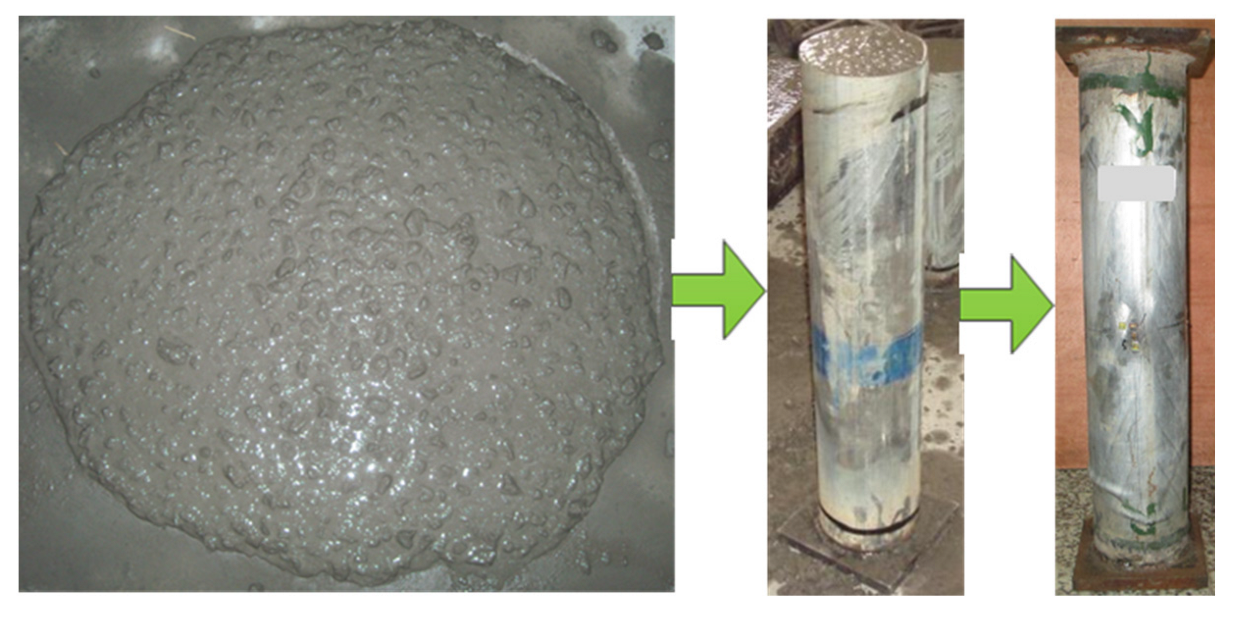
2.1. Raw Materials and Specimen Preparation
2.2. Material Properties
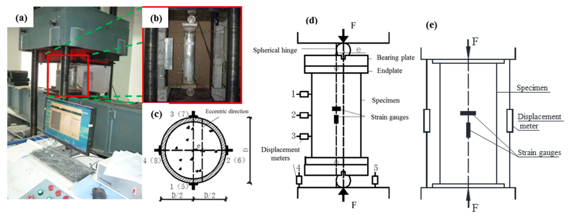
2.3. Test Setup and Procedure
3. Results and Analysis
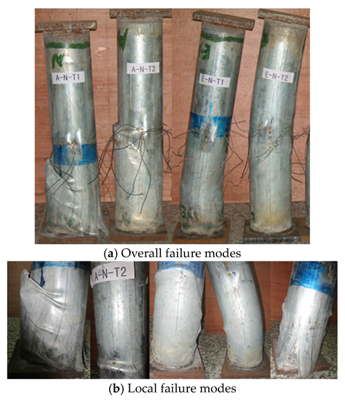
3.1. Characteristics at Failure Stage
3.2. Relations between Displacement and Load
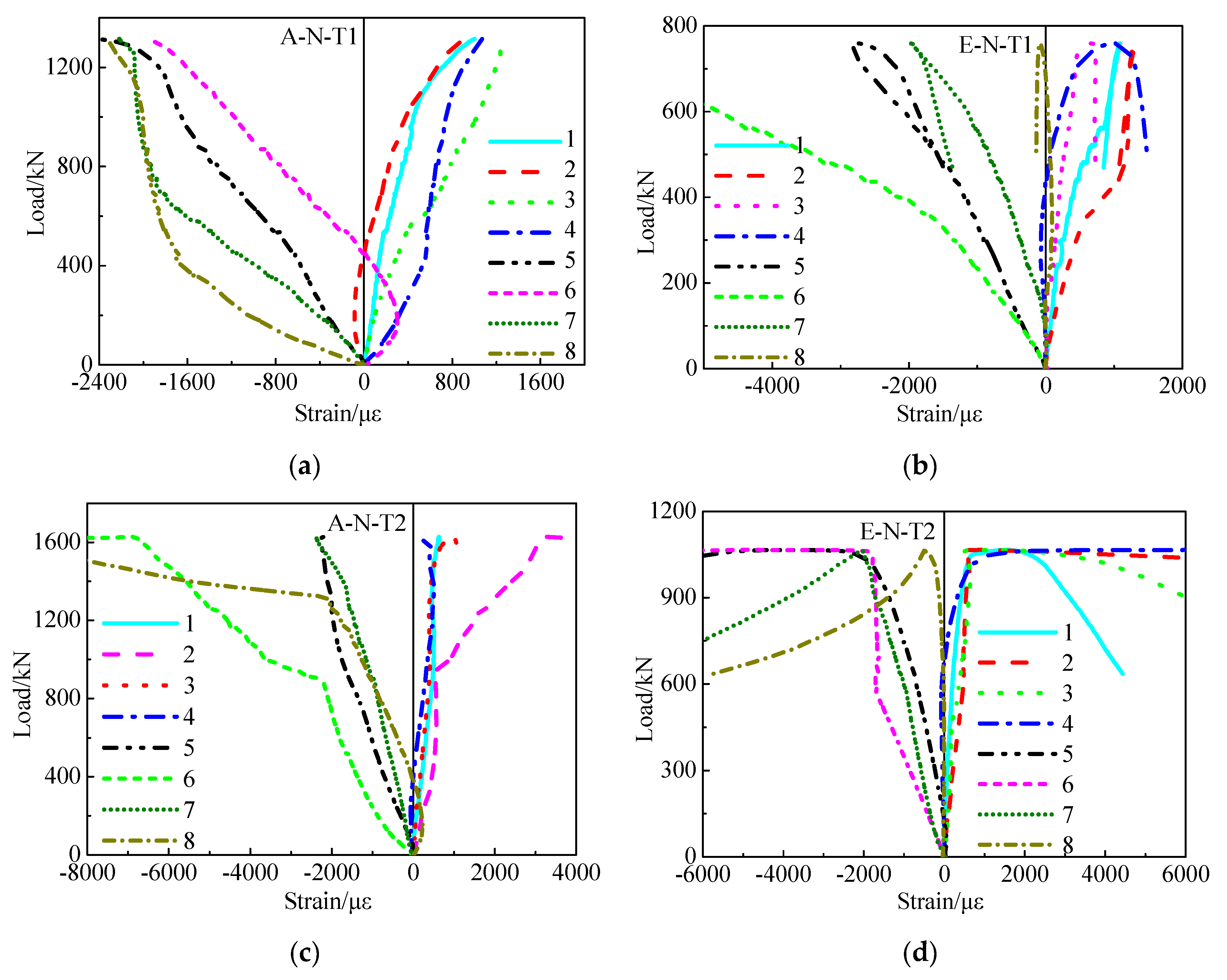
3.3. Relations between Load and Strain
3.4. Relations between Load and Lateral Deflection
3.5. Coefficient of Displacement Ductility
4. Conclusions
- Both lateral deflection and buckling were the main failure characteristics of the eccentrically loaded columns, while the columns withstanding axial load displayed bulking and rupture of the columns. The amount of bulking decreased upon increasing wall thickness.
- The descent phase of the relations between load and displacement of the eccentrically loaded columns was more gently compared with the axially loaded columns. The descent phase became more gently with increase of the wall thickness. In comparison with the axially loaded columns, the ultimate load of the eccentrically loaded columns decreased by 43.0% and 34.5%, respectively, corresponding to the wall thickness factors 116.7 and 46.7.
- Theoretical calculation formulas on predicting the ultimate loads of the columns subjected to eccentric compression were proposed, and the proposed curves coincided well with the tested curves. Meanwhile, the ratios of the ultimate loads calculated using design codes to the tested values were under the range of 0.70~0.90. This implies that the design codes can conservatively predict the ultimate loads. Additionally, the ratios of the ultimate loads calculated using the proposed formulas to the tested values were within the range of 0.99~1.08; it was demonstrated that the proposed formulas predicting the ultimate loads of the SCCTST columns withstanding eccentric compression are more accurate than those of the design codes.
- Initial stiffness of eccentrically loaded columns was reduced by 14.1% and 25.4%, respectively, compared with the axially loaded columns corresponding to wall thickness factors 116.7 and 46.7. When decreasing the wall thickness factor from 116.7 to 46.7, initial stiffness of the eccentrically loaded columns increased by 19.3%, while the displacements at the ultimate loads of the eccentrically loaded columns decreased by 18.1% and increased by 3.9%, respectively.
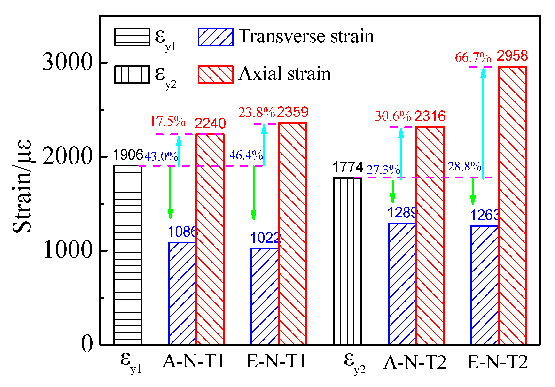
- The strains developed nonlinearly with increases of the load. Compared with the yield strain, the average strain εue of the columns withstanding eccentric load in axial and transverse directions was correspondingly increased by 23.8%/66.7% and decreased by 46.4%/28.8%, respectively. The εue was almost increased with increasing wall thickness.
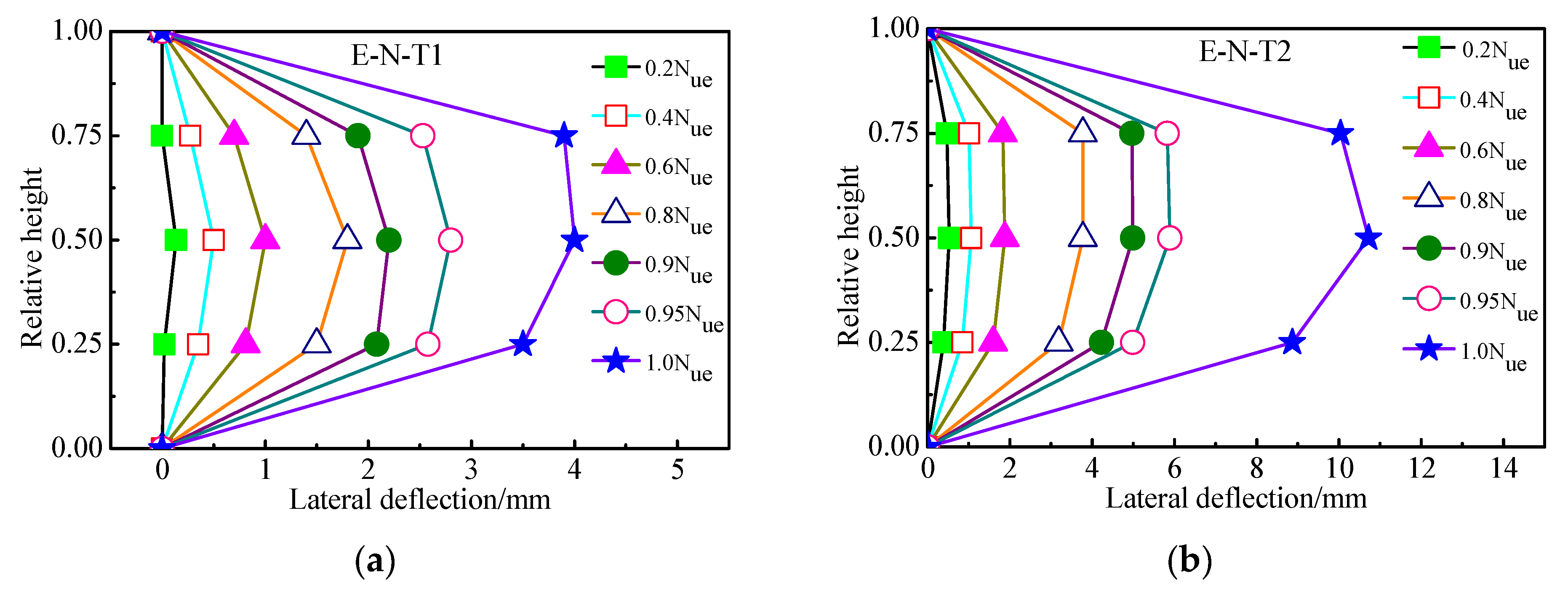
- Lateral deflections of the columns withstanding eccentric load proximately increased linearly with load increasing up to 70% of the maximum load. After that, the increase rate of load was slower than that of the lateral deflection, and the relations between lateral deflection and load were nonlinear. The average lateral deflection corresponding to the ultimate load with wall thickness of 3.0 mm increased by 162.3% compared with that with the wall thickness of 1.2 mm. The lateral deflection along the columns’ height was proximately symmetrical at different loading levels. The symmetry of the lateral deflection and the ductility was more evident with increasing wall thickness.
Author Contributions
Funding
Institutional Review Board Statement
Informed Consent Statement
Data Availability Statement
Acknowledgments
Conflicts of Interest
References
- Miao, K.; Wei, Y.; Zhang, S.; Zheng, K.; Ding, M. Eccentric compression behavior of concrete-filled steel tube columns strengthened by CFRP/steel strip. Eng. Struct. 2023, 287, 116191. [Google Scholar] [CrossRef]
- Wei, Y.; Jiang, C.; Wu, Y. Confinement effectiveness of circular concrete-filled steel tubular columns under axial compression. J. Constr. Steel Res. 2019, 158, 15–27. [Google Scholar] [CrossRef]
- Le, K.B.; Van Cao, V.; Cao, H.X. Circular concrete filled thin-walled steel tubes under pure torsion: Experiments. Thin-Walled Struct. 2021, 164, 107874. [Google Scholar] [CrossRef]
- Cao, V.V.; Le, Q.D.; Nguyen, P.T. Experimental behaviour of concrete-filled steel tubes under cyclic axial compression. Adv. Struct. Eng. 2020, 23, 74–88. [Google Scholar] [CrossRef]
- Abed, F.; Alhamaydeh, M.; Abdalla, S. Experimental and numerical investigations of the compressive behavior of concrete filled steel tubes (CFSTs). J. Constr. Steel Res. 2013, 80, 429–439. [Google Scholar] [CrossRef]
- Shehnaz, S.M.; Shah SM, I.; Ganesh, G.M. Experimental and theoretical study on rectangular concrete filled steel tube columns subjected to axial compression. Mater. Today Proc. 2022, 65, 771–776. [Google Scholar] [CrossRef]
- Skalomenos, K.A.; Hayashi, K.; Nishi, R.; Hiroyuki, I.; Masayoshi, N. Experimental behavior of concrete-filled steel tube columns using ultrahigh-strength steel. J. Struct. Eng. 2016, 142, 4016057. [Google Scholar] [CrossRef]
- Han, L.; An, Y. Performance of concrete-encased CFST stub columns under axial compression. J. Constr. Steel Res. 2014, 93, 62–76. [Google Scholar] [CrossRef]
- Wang, X.; Fan, F.; Lai, J. Strength behavior of circular concrete-filled steel tube stub columns under axial compression, A review. Constr. Build. Mater. 2022, 322, 126144. [Google Scholar] [CrossRef]
- Ayough, P.; Ibrahim, Z.; Sulong, N.R.; Po-Chien, C. The effects of cross-sectional shapes on the axial performance of concrete-filled steel tube columns. J. Constr. Steel Res. 2021, 176, 106424. [Google Scholar] [CrossRef]
- Chang, X.; Luo, X.; Zhu, C.; Tang, C. Analysis of circular concrete-filled steel tube (CFT) support in high ground stress conditions. Tunn. Undergr. Space Technol. 2014, 43, 41–48. [Google Scholar] [CrossRef]
- Wei, J.; Luo, X.; Lai, Z. Experimental behavior and design of high-strength circular concrete-filled steel tube short columns. J. Struct. Eng. 2020, 146, 4019184. [Google Scholar] [CrossRef]
- Zhu, J.; Chen, J.; Chan, T. Analytical model for circular high strength concrete filled steel tubes under compression. Eng. Struct. 2021, 244, 112720. [Google Scholar] [CrossRef]
- Fujimoto, T.; Mukai, A.; Nishiyama, I.; Sakino, K. Behavior of eccentrically loaded concrete-filled steel tubular columns. J. Struct. Eng. 2004, 130, 203–212. [Google Scholar] [CrossRef]
- Portolés, J.M.; Romero, M.L.; Bonet, J.L.; Filippou, F.C. Experimental study of high strength concrete-filled circular tubular columns under eccentric loading. J. Constr. Steel Res. 2011, 67, 623–633. [Google Scholar] [CrossRef]
- Lee, S.H.; Uy, B.; Kim, S.H.; Choi, Y.H.; Choi, S.M. Behavior of high-strength circular concrete-filled steel tubular (CFST) column under eccentric loading. J. Constr. Steel Res. 2011, 67, 1–13. [Google Scholar] [CrossRef]
- Li, G.; Chen, B.; Yang, Z.; Feng, Y. Experimental and numerical behavior of eccentrically loaded square concrete-filled steel tubular long columns made of high-strength steel and concrete. Thin-Walled Struct. 2021, 159, 107289. [Google Scholar] [CrossRef]
- Liu, D. Behaviour of eccentrically loaded high-strength rectangular concrete-filled steel tubular columns. J. Constr. Steel Res. 2006, 62, 839–846. [Google Scholar] [CrossRef]
- Younas, S.; Hamed, E.; Li, D.; Uy, B. Eccentrically loaded concrete-filled steel tubes made with high strength materials. Eng. Struct. 2023, 275, 115246. [Google Scholar] [CrossRef]
- Li, G.; Chen, B.; Yang, Z.; Feng, Y. Experimental and numerical behaviour of eccentrically loaded high strength concrete filled high strength square steel tube stub columns. Thin-Walled Struct. 2018, 127, 483–499. [Google Scholar] [CrossRef]
- Tam, V.W.; Xiao, J.; Liu, S. Behaviors of recycled aggregate concrete-filled steel tubular columns under eccentric loadings. Front. Struct. Civil. Eng. 2019, 13, 628–639. [Google Scholar] [CrossRef]
- Zhang, R.; Chen, S.; Gu, P.; Huang, Y. Structural behavior of UHPC filled steel tubular columns under eccentric loading. Thin-Walled Struct. 2020, 156, 106959. [Google Scholar] [CrossRef]
- Wang, J.; Sun, Q. Cyclic testing of Q690 circular high-strength concrete-filled thin-walled steel tubular columns. Adv. Struct. Eng. 2019, 22, 444–458. [Google Scholar] [CrossRef]
- Li, J.X.; Wang, J.T.; Sun, Q.; Wu, Y.R.; Zhou, S.M.; Wang, F.C. Axial compression behavior of circular concrete-filled high-strength thin-walled steel tubular columns with out-of-code D/t ratios. Adv. Mater. Sci. Eng. 2021, 2021, 9081566. [Google Scholar] [CrossRef]
- Lyu, X.; Xu, Y.; Xu, Q.; Yu, Y. Axial compression performance of square thin walled concrete-Filled steel tube stub columns with reinforcement stiffener under constant high-Temperature. Materials 2019, 12, 1098. [Google Scholar] [CrossRef] [PubMed]
- CECS 28–2012; Technical Specification for Concrete-Filled Steel Tubular Structures. China Planning Press: Beijing, China, 2012.
- GB 50936–2014; Technical Code for Concrete Filled Steel Tubular Structures. Gb: Beijing, China, 2014.
- Tao, Z.; Han, L.; Wang, D. Experimental behaviour of concrete-filled stiffened thin-walled steel tubular columns. Thin-Walled Struct. 2007, 45, 517–527. [Google Scholar] [CrossRef]
- Petrus, C.; Hamid, H.A.; Ibrahim, A.; Parke, G. Experimental behaviour of concrete filled thin walled steel tubes with tab stiffeners. J. Constr. Steel Res. 2010, 66, 915–922. [Google Scholar] [CrossRef]
- Wu, B.; Lin, L.; Zhao, J.; Yan, H. Creep behavior of thin-walled circular steel tubular columns filled with demolished concrete lumps and fresh concrete. Constr. Build. Mater. 2018, 187, 773–790. [Google Scholar] [CrossRef]
- Liu, J.; Teng, Y.; Zhang, Y.; Wang, X.; Chen, Y.F. Axial stress-strain behavior of high-strength concrete confined by circular thin-walled steel tubes. Constr. Build. Mater. 2018, 177, 366–377. [Google Scholar] [CrossRef]
- Wang, J.; Sun, Q.; Li, J. Experimental study on seismic behavior of high-strength circular concrete-filled thin-walled steel tubular columns. Eng. Struct. 2019, 182, 403–415. [Google Scholar] [CrossRef]
- Jiang, A.; Chen, J.; Jin, W. Experimental investigation and design of thin-walled concrete-filled steel tubes subject to bending. Thin-Walled Struct. 2013, 63, 44–50. [Google Scholar] [CrossRef]
- Wang, J.; Shen, Q.; Jiang, H.; Pan, X. Analysis and design of elliptical concrete-filled thin-walled steel stub columns under axial compression. Int. J. Steel Struct. 2018, 18, 365–380. [Google Scholar] [CrossRef]
- Cakiroglu, C.; Islam, K.; Bekdaş, G.; Isikdag, U.; Mangalathu, S. Explainable machine learning models for predicting the axial compression capacity of concrete filled steel tubular columns. Constr. Build. Mater. 2022, 356, 129227. [Google Scholar] [CrossRef]
- Li, N.; Jin, Z.; Long, G.; Chen, L.; Fu, Q.; Yu, Y.; Zhang, X.; Xiong, C. Impact resistance of steel fiber-reinforced self-compacting concrete (SCC) at high strain rates. J. Build. Eng. 2021, 38, 102212. [Google Scholar] [CrossRef]
- Long, G.; Gao, Y.; Xie, Y. Designing more sustainable and greener self-compacting concrete. Constr. Build. Mater. 2015, 84, 301–306. [Google Scholar] [CrossRef]
- Gupta, N.; Siddique, R.; Belarbi, R. Sustainable and greener self-compacting concrete incorporating industrial by-products, a review. J. Clean. Prod. 2021, 284, 124803. [Google Scholar] [CrossRef]
- Cakiroglu, C.; Bekdaş, G.; Kim, S.; Geem, Z.W. Explainable ensemble learning models for the rheological properties of self-compacting concrete. Sustainability 2022, 14, 14640. [Google Scholar] [CrossRef]
- Saba, A.M.; Khan, A.H.; Akhtar, M.N.; Khan, N.A.; Koloor, S.S.; Petru, M.; Radwan, N. Strength and flexural behavior of steel fiber and silica fume incorporated self-compacting concrete. J. Mater. Res. Technol. 2021, 12, 1380–1390. [Google Scholar] [CrossRef]
- Yuan, J.; Zhao, M.; Esmaeili Falak, M. A comparative study on predicting the rapid chloride permeability of self-compacting concrete using meta-heuristic algorithm and artificial intelligence techniques. Struct. Concr. 2022, 23, 753–774. [Google Scholar] [CrossRef]
- Wang, Y.; Zhang, L.; Jia, Y.; Li, L. Experimental Study on Self-Compacting Concrete-Filled Thin-Walled Steel Tube Columns. Buildings 2022, 12, 2134. [Google Scholar] [CrossRef]
- Chen, J.; Jin, W. Experimental investigation of thin-walled complex section concrete-filled steel stub columns. Thin-Walled Struct. 2010, 48, 718–724. [Google Scholar] [CrossRef]
- Yang, Y.F.; Han, L.H. Behaviour of concrete filled steel tubular (CFST) stub columns under eccentric partial compression. Thin-Walled Struct. 2011, 49, 379–395. [Google Scholar] [CrossRef]
- GB/T 228.1-2021; Standard for Tensile Testing Method of Metallic Materials. Standards Press of China: Beijing, China, 2021.
- GB/T 50081-2002; Standard for Test Methods for Mechanical Properties of ordinary Concrete. China Architecture & Building Press: Beijing, China, 2002.
- CECS 28:90; Specification for Design and Construction of Concrete Filled Steel Tubular Structures. China Planning Press: Beijing, China, 1991.
- DL/T 5085-1999; Code for Design of Steel-Concrete Composite Structure. China Planning Press: Beijing, China, 1999.
- Shi, X.S.; Wang, Q.Y.; Zhao, X.L.; Collins, F. Strength and Ductility of Recycled Aggregate Concrete Filled Composite Tubular Stub Columns; Incorporating Sustainable Practice in Mechanics of Structures and Materials: London, UK, 2011; pp. 83–89. [Google Scholar]
- Wang, Y.; Chen, J.; Geng, Y. Testing and analysis of axially loaded normal-strength recycled aggregate concrete filled steel tubular stub columns. Eng. Struct. 2015, 86, 192–212. [Google Scholar] [CrossRef]
- Tam, V.W.; Wang, Z.; Tao, Z. Behaviour of recycled aggregate concrete filled stainless steel stub columns. Mater. Struct. 2014, 47, 293–310. [Google Scholar] [CrossRef]
- Zhang, F.; Xia, J.; Li, G.; Guo, Z.; Chang, H.; Wang, K. Degradation of axial ultimate load-bearing capacity of circular thin-walled concrete-filled steel tubular stub columns after corrosion. Materials 2020, 13, 795. [Google Scholar] [CrossRef]
- Giakoumelis, G.; Lam, D. Axial capacity of circular concrete-filled tube columns. J. Constr. Steel Res. 2004, 60, 1049–1068. [Google Scholar] [CrossRef]
- Han, L.; Yao, G. Experimental behaviour of thin-walled hollow structural steel (HSS) columns filled with self-consolidating concrete (SCC). Thin-Walled Struct. 2004, 42, 1357–1377. [Google Scholar] [CrossRef]
- Liu, J.; Zhang, S.; Zhang, X.; Guo, L. Behavior and strength of circular tube confined reinforced-concrete (CTRC) columns. J. Constr. Steel Res. 2009, 65, 1447–1458. [Google Scholar] [CrossRef]
- Yu, F.; Qin, C.; Wang, S.; Jiang, J.; Fang, Y. Stress-strain relationship of recycled self-compacting concrete filled steel tubular column subjected to eccentric compression. Front. Struct. Civil. Eng. 2020, 14, 760–772. [Google Scholar] [CrossRef]
- Han, L.H. Concrete Filled Steel Tube Structures-Theory and Practice; Science Press: Beijing, China, 2004. [Google Scholar]


| Numbers | D × t × L (mm3) | L/D | As (mm2) | e (mm) | e/r | As/Ac (%) |
|---|---|---|---|---|---|---|
| A–N–T1 | 140 × 1.2 × 700 | 5.0 | 519.2 | 0 | 0 | 3.4 |
| E–N–T1 | 140 × 1.2 × 700 | 5.0 | 519.2 | 20 | 0.29 | 3.4 |
| A–N–T2 | 140 × 3.0 × 700 | 5.0 | 1290.5 | 0 | 0 | 8.4 |
| E–N–T2 | 140 × 3.0 × 700 | 5.0 | 1290.5 | 20 | 0.29 | 8.4 |
| Coarse Aggregate | Fine Aggregate | Cement | Water | Fly Ash | Superplasticizer (wt.%) |
|---|---|---|---|---|---|
| 769 | 837 | 402 | 199 | 122 | 0.4 |
| Modulus of Elasticity (GPa) | Yield Strength (MPa) | Poisson’s Ratio | Wall Thickness (mm) |
|---|---|---|---|
| 181.0 | 345.0 | 0.30 | 1.2 |
| 202.0 | 358.3 | 0.28 | 3.0 |
| Numbers | Nue * | CECS | DL/T | Proposed Formulas | |||
|---|---|---|---|---|---|---|---|
| (kN) | Nuc * (kN) | Nuc/Nue | Nuc * (kN) | Nuc/Nue | Nuc * (kN) | Nuc/Nue | |
| A–N–T1 | 1331.0 | 1047.8 | 0.79 | 1059.9 | 0.80 | - | - |
| E–N–T1 | 759.0 | 679.6 | 0.90 | 555.3 | 0.73 | 751.6 | 0.99 |
| A–N–T2 | 1627.8 | 1426.0 | 0.88 | 1356.7 | 0.83 | - | - |
| E–N–T2 | 1065.8 | 918.7 | 0.86 | 713.1 | 0.70 | 1148.7 | 1.08 |
| D (mm) | t (mm) | L (mm) | Slenderness | fc * (MPa) | fy * (MPa) | e * (mm) | Nue * (kN) | References |
|---|---|---|---|---|---|---|---|---|
| 114 | 1.7–2.09 | 394–402 | 3.5 | 29.2–35.6 | 300.3 | 0 | 557–688 | [49] |
| 133–140 | 2.64–4.66 | 400–420 | 3.0 | 36.9–52.9 | 302–335.3 | 0 | 1070–1749 | [50] |
| 138–170.6 | 2.79–2.86 | 420–510 | 3.0 | 36.3–40.0 | 339.6–388.5 | 0 | 1147.5–1607.4 | [51] |
| 139 | 0.92–1.92 | 500 | 3.6 | 32.6 | 238 | 0 | 505.6–931.9 | [52] |
| 114–167 | 3.1–5.6 | 250–350 | 2.1–2.2 | 44–60 | 300 | 0 | 1042–1873 | [5] |
| 114–115 | 3.84–5.02 | 298–300 | 2.6 | 31–104.9 | 343–365 | 0 | 929–1787 | [53] |
| 100–200 | 3.0 | 300–600 | 3.0 | 50 | 303.5 | 0 | 708–2594 | [54] |
| 133–159 | 3.1–6.2 | 399–477 | 3.0 | 75.1–80.7 | 331.7–392 | 0 | 2185–3031 | [55] |
| 150–180 | 3.0 | 450–540 | 3.0 | 59.3 | 324.4 | 0–30 | 689–1618 | [44] |
| 140 | 3.63 | 500–1500 | 3.6–10.7 | 30–60 | 233 | 0–60 | 391–773 | [56] |
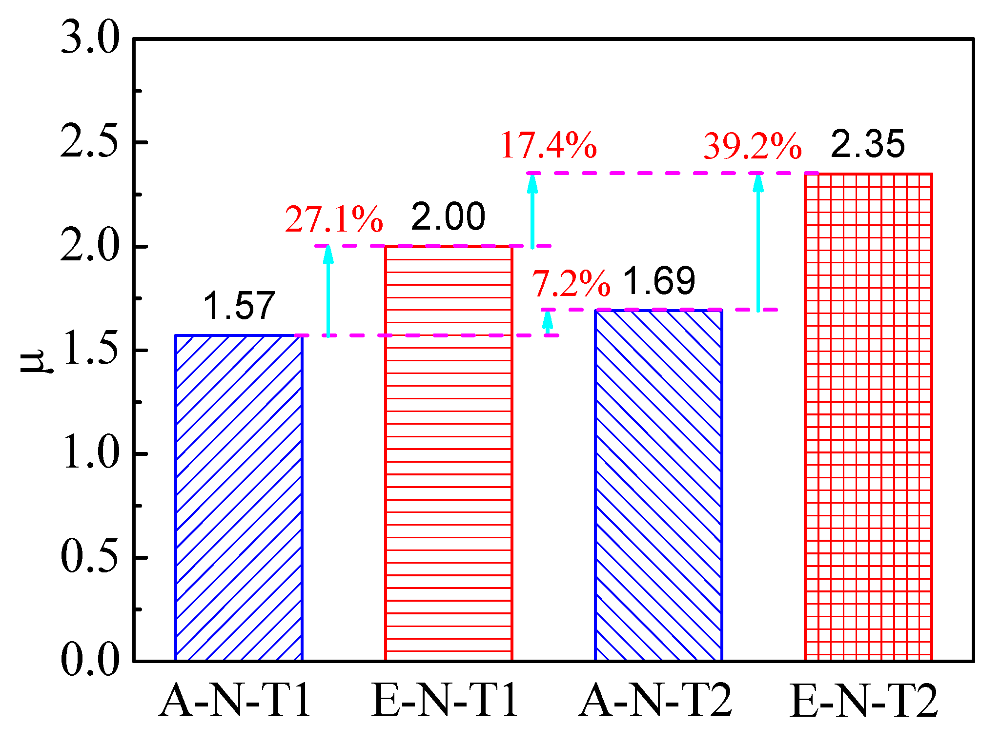
| Numbers | Δy (mm) | Δu (mm) | µ |
|---|---|---|---|
| A–N–T1 | 4.49 | 7.07 | 1.57 |
| E–N–T1 | 3.20 | 6.40 | 2.00 |
| A–N–T2 | 4.21 | 7.10 | 1.69 |
| E–N–T2 | 3.60 | 8.44 | 2.35 |
Disclaimer/Publisher’s Note: The statements, opinions and data contained in all publications are solely those of the individual author(s) and contributor(s) and not of MDPI and/or the editor(s). MDPI and/or the editor(s) disclaim responsibility for any injury to people or property resulting from any ideas, methods, instructions or products referred to in the content. |
© 2023 by the authors. Licensee MDPI, Basel, Switzerland. This article is an open access article distributed under the terms and conditions of the Creative Commons Attribution (CC BY) license (https://creativecommons.org/licenses/by/4.0/).
Share and Cite
Wang, Y.; Sun, S.; Zhang, L.; Jia, Y.; Yang, G.; Li, M.; Tan, W.; Qu, J. Eccentric Compression Behaviors of Self-Compacting Concrete-Filled Thin-Walled Steel Tube Columns. Materials 2023, 16, 6330. https://doi.org/10.3390/ma16186330
Wang Y, Sun S, Zhang L, Jia Y, Yang G, Li M, Tan W, Qu J. Eccentric Compression Behaviors of Self-Compacting Concrete-Filled Thin-Walled Steel Tube Columns. Materials. 2023; 16(18):6330. https://doi.org/10.3390/ma16186330
Chicago/Turabian StyleWang, Yunyang, Shengwei Sun, Liqing Zhang, Yandong Jia, Guang Yang, Meng Li, Wei Tan, and Jianmin Qu. 2023. "Eccentric Compression Behaviors of Self-Compacting Concrete-Filled Thin-Walled Steel Tube Columns" Materials 16, no. 18: 6330. https://doi.org/10.3390/ma16186330
APA StyleWang, Y., Sun, S., Zhang, L., Jia, Y., Yang, G., Li, M., Tan, W., & Qu, J. (2023). Eccentric Compression Behaviors of Self-Compacting Concrete-Filled Thin-Walled Steel Tube Columns. Materials, 16(18), 6330. https://doi.org/10.3390/ma16186330