1. Introduction
316L stainless steel is an austenitic stainless-steel material containing a certain number of microelements, such as Cr and Ni, and has good thermal plasticity and wear resistance. It is widely used to manufacture precision equipment, such as aviation engine parts, and transportation and electronic communication parts [
1,
2]. Thin-walled parts refer to workpieces whose wall thickness to profile size ratio does not exceed 1:20. Manufacturing thin-walled parts has always been a key research topic in traditional manufacturing industries. The clamping structure and clamping force, tool selection, cutting process parameters, and other factors have a significant impact on thin-walled parts. Moreover, the production of thin-walled components is also limited by factors such as inadequate cutting rigidity and vibration during machining. Additive manufacturing (AM), also known as 3D printing, is defined as the “process of joining materials to make objects from 3D model data usually layer upon layer, as opposed to traditional manufacturing technologies such as subtractive manufacturing” [
3]. This unique manufacturing method has created enormous potential for producing parts with complex geometries while reducing material waste and shortening the time to market [
4]. Different types of AM technologies have been developed, which can be classified according to different factors, including raw materials and building methods [
5].
Due to its advantages in manufacturing complex geometries and reducing material waste, AM has been applied in many fields [
6]. However, some AM limitations have hindered its comprehensive application in different industries. For example, AM parts typically have lower accuracy and strength [
7], poor surface quality [
8], and longer manufacturing times [
9]. Therefore, improving AM processes’ size and mechanical properties is necessary while shortening production time [
10]. At the same time, AM still faces some technical bottlenecks, such as internal stresses caused by transient melting/solidification of the cladding layer during laser additive manufacturing, which seriously affects the geometric dimensions and mechanical properties of the parts, leading to severe deformation and cracking of the parts [
11]. After a single-layer laser scan, there are high residual tensile stresses in the solidified layer, and the internal stresses accumulate continuously after multiple layers are stacked, making the parts prone to deformation and cracking [
12,
13], thereby seriously affecting the strength and forming accuracy of the parts. These are the problems that urgently need to be solved in additive manufacturing.
Additive/Subtractive Hybrid Manufacturing (ASHM) is an emerging manufacturing technology that combines the advantages of Additive Manufacturing (AM) and traditional Subtractive Manufacturing (SM) [
14,
15]. This technology relies on Laser Metal Deposition (LMD), which combines AM and SM and can produce parts with complex geometries, as well as good surface finish and dimensional accuracy [
16]. In ASHM-based Selective Laser Melting (SLM), after the scanning laser beam forms multiple powder layers, the milling cutter machines the finished parts, and the next SLM process begins. The additive and subtractive processes are repeated alternately until the part is manufactured [
17]. ASHM is one of the most effective methods to improve the surface quality and dimensional accuracy of complex AM samples [
18,
19,
20]. The mixed additive and subtractive manufacturing process is gaining popularity as an effective solution to overcome the limitations of AM while also enhancing the dimensional accuracy and surface quality of parts [
21].
Hybrid-layered manufacturing refers to the alternating use of additive manufacturing and subtractive machining without changing the workpiece’s position, fixture, or reference surface, thereby reducing machining errors caused by repeated positioning. Its advantages are particularly evident in processing thin-walled parts with complex curved surfaces, internal structures, and enclosed cavities. Processing thin-walled parts with complex curved surfaces and internal structures poses significant challenges for traditional machining methods. However, hybrid-layered manufacturing technology optimizes the benefits of additive and subtractive manufacturing by initially milling the inner cavity of the part, followed by a second additive manufacturing step. This approach circumvents tool–workpiece interference and addresses the issue of inaccessible cavity regions during machining; therefore, hybrid-layered manufacturing technology is considered an efficient and precise machining method that can greatly improve production efficiency and reduce costs.
Yang et al. [
22] conducted additive/subtractive hybrid manufacturing experiments on 316L stainless steel using an integrated additive DED process and CNC milling machine. Different laser powers (
p), scanning speeds (
v), and laser scanning paths were used in the experiments. The results showed that the depth and width of the additive melt pool were significantly affected by
,
and the additive parts’ mechanical properties exhibited anisotropy in different printing directions. Gong et al. [
23] also used the DED process combined with CNC milling to conduct ASHM experiments on 316L stainless steel. The finished parts were machined after deposition, and various deposition paths were used to study the influence of deposition paths on the final part quality. The hardness and mechanical properties test results showed that the “S”-type deposition method obtained higher hardness, yield strength (479 MPa) under tensile loading, and ultimate tensile strength (688 MPa). Zhao et al. [
24] systematically studied the microstructure and properties of WC particle-reinforced 316L stainless steel produced by additive/subtractive hybrid manufacturing. The effects of process parameters on part properties were comprehensively described from aspects such as density, microstructure, hardness, and surface quality. The results showed that laser power and scanning speed had a particularly significant impact on part properties. Wei Du et al. [
25] conducted additive/subtractive hybrid manufacturing on 18Ni-300 maraging steel samples. The results showed that the selective laser melting (SLM) sample had a finer cellular microstructure with dendritic extensions than the forged sample. The ASHM samples had a 31.6% higher hardness than the forged samples and exhibited directionality independence. Under the same cutting conditions, the cutting force of the SLM samples was higher than that of the forged samples. At a high feed rate of 320 mm/min, the difference in cutting force between the two samples increased to 29.8%. Chen F et al. [
26] conducted powder-fed laser additive manufacturing and milling subtractive manufacturing. The additive and milling processes alternated during manufacturing, with milling performed every 2 mm of deposition until the entire sample was completed. The subsequent analysis of the workpiece detection results showed that the surface microhardness of the ASHM samples was 11.2% and 33.7% higher than that of the AM samples and forged parts, respectively. The tensile strength and yield strength under tensile loading were increased by about 5% and 60.5%, respectively, while the elongation at break was slightly reduced.
In 2018, Lockheed Martin used electron beam additive and subtractive manufacturing technology to produce the largest 3D-printed space component to date—a satellite fuel tank. Utilizing this process, the component achieved over 80% reduction in material waste and reduced the overall delivery time from two years to three months. The part underwent rigorous quality testing, enabling it to withstand the harsh demands of launch and perform reliably in the vacuum of space for several decades. Currently, this component is being utilized as a standard part of the LM 2100 satellite platform.
DMG MORI’s unique hybrid (combining additive manufacturing with traditional manufacturing) machining solution is a remarkable technology that integrates milling techniques with laser metal deposition processes. It is applied on a laser deposition machine tool that possesses complete milling capabilities. In May 2019, Virgin Orbit, a satellite launch company, utilized DMG MORI’s additive and subtractive integrated equipment to 3D print engine combustion chambers for NASA. The interior lining of the chambers was made of GRCop-84 copper alloy, while the exterior was composed of nickel-based high-temperature alloy. The structure and materials were identical to traditional designs, but the manufacturing time was reduced by several months.
The study of the additive and subtractive hybrid manufacturing process with alternating increments and reductions is difficult and complex. Currently, most research focuses on the post-additive/subtractive manufacturing process, where the material is first added and then subtracted. In alternating between additive and subtractive manufacturing, it is essential to consider not only the impact of these processes on part quality but also factors such as thermal cutting, the timing of additive and subtractive steps, and temperature distribution across additively manufactured parts during cutting. Currently, there is a relative lack of research in this area, thus necessitating an investigation into the process of alternating additive and subtractive manufacturing.
In this study, we investigate the utilization of additive and subtractive manufacturing tools to evaluate the additive and subtractive processes for thin-walled box components along two distinct paths. The experimental process and resulting data were acquired through a laser displacement sensor, which effectively characterized the deformation patterns exhibited by the box-shaped thin-walled part during additive/subtractive processing with different paths, thereby elucidating the underlying causes for deformation patterns.
In this article, the deposition manufacturing of a thin-walled part is carried out on a rectangular substrate. First, the laser beam generates a melt pool on the substrate surface, and then the metal powder is sprayed into the melt pool through a powder feeder, forming the first layer. As the laser beam scans layer by layer, the melt pool gradually moves upward. The powder is sprayed into the melt pool and gradually melts, forming a new melt pool. In this new melt pool, the laser beam continues to scan and melt the powder, thus adding material layer by layer. After depositing 20 layers, the surface of the additive manufacturing part is milled to improve the surface quality. The above operations are repeated until the box-shaped thin-walled part is completed. The schematic diagram of the part-forming process is shown in
Figure 1.
2. Theoretical Analysis of Additive and Subtractive Hybrid Manufacturing Process
2.1. Heat Transfer Analysis of Additive Hybrid Manufacturing Process
During the laser additive manufacturing process, the melted metal powder is layered and deposited on the substrate as the high-energy laser beam moves back and forth. This process involves melting and solidifying the metal material, transforming the metallographic structure, etc. For isotropic materials, the heat transfer behaviors, such as conduction, convection, and thermal radiation among the melt pool, cladding layer, substrate, and the surrounding air, can be described by the heat transfer differential equations.
where
is the material density,
;
is the material specific heat capacity,
;
denotes the material transient temperature,
;
denotes time,
; and
,
, and
denote the thermal conductivity in the
,
, and
directions,
. When the material is isotropic,
.
The thermal boundary conditions in the additive process include the laser heat source, the convection of the cladding layer in contact with the air, and the thermal radiation boundary. A two-dimensional Gaussian heat source is used to describe the laser energy distribution heat source, and the maximum heat flow density at the center of the laser spot is:
where
is the thermal efficiency;
is the laser power; and
is the spot diameter. Combined with the Gaussian function so that the volumetric heat generation rate is Gaussian distributed within the cell, the Gaussian heat source used in the numerical simulation is defined by the following equation:
where
is the thickness per unit volume and
is the incremental spot diameter; the heat flow rate decreases with increasing diameter, according to the grid model to choose the initial value, wherein the initial value in this paper is 1 and the increment is 0.5.
The convective heat transfer between a flowing fluid and a solid is proportional to its temperature difference and can be expressed by the following equation:
where
is the heat exchanged between the solid surface and fluid per unit area per unit time, called heat flow density, unit
;
is the solid surface temperature;
is the fluid temperature; and
is the convective heat transfer coefficient, with a natural convection for 5~25 and gas-forced convection for 25~300. The net radiation heat transfer rate equation can express thermal radiation:
where
is the heat emitted per unit area of the solid surface, with units of
;
is the emissivity, typically ranging from 0 to 1;
is the Stefan–Boltzmann constant, which is
;
is the solid temperature; and
is the ambient temperature.
ensures the convergence of temperature calculation in the LMD additive forming process, the convective and radiative heat transfer are combined
, and a factor
is introduced. This leads to the radiative–convective boundary heat transfer equation:
2.2. Thermal Stress Analysis of Additive Hybrid Manufacturing Process
The LMD stress and deformation simulation is based on the numerical simulation results of the temperature field. By applying boundary conditions in static analysis, the software can read the temperature history of all nodes and calculate the resulting stress and deformation of the model.
Currently, the stress distribution in laser additive manufacturing is usually analyzed based on the theory of thermo-elasto-plasticity. In the stress–strain relationship of thermo-elasto-plastic mechanics, a term of strain caused by temperature change is added while considering the effect of temperature on yield stress, etc. Given that the stress changes in the LMD process are very complex, it is necessary to perform reasonable and moderate simplification when conducting thermo-elasto-plastic analysis. It is usually based on the assumptions that (1) the yield criterion for metallic materials is based on the Von–Mises criterion, and (2) the flow criterion and the hardening criterion are satisfied when the metallic material is in the plastic region.
According to the Von–Mises criterion, the component undergoes yielding when the equivalent stress exceeds the yield stress.
where,
,
,
is the positive pressure in
,
,
direction; and
,
,
is the shear stress.
The flow criterion defines the magnitude and direction of the plastic strain components when the material undergoes plastic deformation. Its differential equation is as follows:
where
is the total stress,
is the total plastic strain, and
is the hardening parameter.
The hardening criterion is used to describe the variations in the yield surface. In this model, known as the kinematic hardening model, the center of the yield surface moves along the yielding direction in stress space, while the size and shape of the yield surface remain unchanged, as shown in
Figure 2.
The thermo-elasto-plastic equation is as follows:
- (1)
Stress–strain relationship
The equation for the stress–strain relationship when the material is in a thermo-elasto-plastic state is as follows:
where
is the stress increment;
is the strain increment;
is the temperature increment;
is the elastic or elastoplastic matrix; and
is the vector related to temperature.
In the elastic region:
where
is the coefficient of linear expansion and
is the temperature.
In the plastic region, it is assumed that the yield condition of the material is:
where
is the yield function and
is a function of the yield stress related to temperature and plastic strain.
According to the plastic flow rule, the plastic strain increment
has the following relationship:
The loading or unloading of the plastic region is judged by . Loading is indicated when , and unloading is indicated when .
- (2)
Equilibrium equation
For a numerical model unit of laser cladding, the following equilibrium equation holds:
where
is the increment of force on the unit node;
is the increment of unit initial strain equivalent node force caused by temperature;
is the increment of node displacement;
is the stiffness matrix of the unit; and
is the matrix linking the strain and nodal displacement vectors in the unit.
Based on the unit being in an elastic or plastic state,
and
replace
and
in the above equation to form the unit stiffness matrix and equivalent node load. Then, the total stiffness matrix
and total load vector
are integrated to obtain the equilibrium equation set for the entire component:
where
.
Considering that there is generally no external force in the laser additive remanufacturing process, the corresponding nodal forces of the unit around each node are self-equalizing force systems, i.e., .
2.3. Thermal Stress Analysis of Subtractive Hybrid Manufacturing Process
In CNC milling, most energy expended during chip deformation is transformed into thermal energy. With an increased cutting speed, there is a corresponding increase in heat generation, thereby significantly affecting machining deformations [
27]. The temperature distribution on the workpiece surface is primarily determined by the temperature fields at the shear plane and tool–workpiece interface in the third deformation zone. It is necessary to analyze separately the shear deformation energy
generated by the heat source in the shear zone and the frictional work
generated by the heat source in the friction zone formed by the tool flank tool face and the workpiece surface, as shown in
Figure 3. It should be noted that although the contact surface temperature of the workpiece and the tool’s flank face obtained during the calculation process is the sum of several deformation zone temperatures, the contact zone is extremely small in length (assuming a maximum dullness value of
for the flank) and the cutting speed is very high. The tool moves quickly through the surface of the workpiece, and the surface of the workpiece has good heat dissipation. Therefore, the temperature of the machined surface of the workpiece is not very high and can be ignored.
2.4. Deformation Processing Method
The deformation model of a workpiece includes two parts: deformation caused by thermal stress and deformation caused by the interaction between the cutting tool and the workpiece. During the additive manufacturing process, due to the high temperature gradient and rapid heating–cooling process, thermal expansion and contraction cause materials to undergo uneven plastic deformation under constraints, generating high residual stress. During the subtractive manufacturing process, on the one hand, the residual stress generated during the additive manufacturing stage will redistribute as materials are removed, resulting in the deformation of the material; on the other hand, due to the thin wall thickness and poor stiffness of the part, deformation occurs under the cutting force of the cutting tool and the workpiece, causing the material removal amount to not reach the theoretical value and resulting in machining errors due to material rebound after processing. These two effects interact with each other, ultimately leading to part deformation.
The “birth–death element” technique is a commonly used numerical simulation method in additive manufacturing, which simulates the molted and to-be-molted parts of the additive process through the “birth” and “death” of the elements. In ANSYS, “dead” elements are not simply removed elements but rather have their stiffness matrix multiplied by a very small factor, which the program defaults to 1 × 10⁻⁶ (can be defined as needed). The mass, specific heat, and strain of the “dead” elements are all set to zero, and their mass and energy will not be included in the solution results.
In the simulation process, the “birth–death element” technique is first used to simulate the additive process, and the material’s morphology after processing is obtained through thermal stress simulation. In the subtractive stage, three-dimensional cutting forces are applied to the mesh positions, causing deformation of the thin-walled part. Material is removed by selecting the coordinate values in the y direction and killing the corresponding elements. After killing, the solution is obtained, and the stress is redistributed, resulting in the final deformation result of the workpiece. The schematic diagram of the milling of thin-walled parts is shown in
Figure 4.
6. Deformation Prediction of Additive and Subtractive Hybrid Manufacturing for 316L Stainless Steel Box-Shaped Thin-Walled Parts
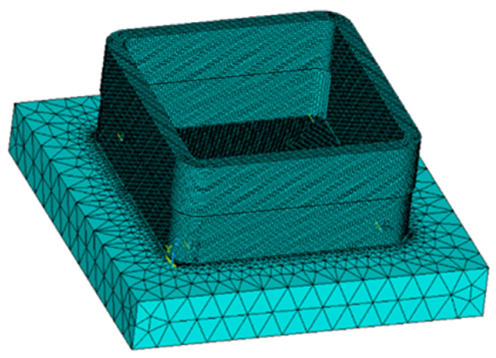
In the above study, path planning of the box-shaped thin-walled part, machine tool motion simulation, and additive manufacturing simulation of the box-shaped thin-walled part were conducted. It was found that the first path planning had the best effect on the box-shaped additive forming, and the finite element model of the box-shaped part was validated through a first-stage additive and subtractive hybrid manufacturing experiment, demonstrating the effectiveness of the box-shaped finite element model. Therefore, based on the above box-shaped simulation, a simulation prediction of the two-stage additive and subtractive hybrid manufacturing of the box-shaped thin-walled part was carried out.
Figure 22 shows the finite element model of the two-stage additive manufacturing of the box-shaped thin-walled part. In the second simulation, the elements milled in the previous stage were “killed” before calculation.
Figure 23 shows the temperature profile of a node during the second stage of additive manufacturing. The black part of the curve represents the “dead” state of the node, while the red part indicates that the node has started to activate and enter the processing stage. The node temperature decreases periodically, and the peak value gets lower until the entire part undergoes natural cooling until it reaches room temperature. This periodic change is also the main source of residual stress during the additive process. The highest temperature experienced by the node was around 2000 °C, which exceeded the melting point of 316L stainless steel.
The residual stress and deformation distribution (enlarged by 10 times) of the second box-shaped thin-walled part is presented in
Figure 24. The overall stress distribution of the box-shaped part is relatively uniform after the second additive manufacturing, with slightly higher stress in the transition area between the first and second stages. This is attributed to the flow effect at both ends, which is caused by the width of the second additive melt path (3 mm) exceeding the thickness after the first milling (2 mm).
The maximum residual stress after the second stage of additive manufacturing is 431 MPa, which is slightly higher than the first stage. In addition, from the stress distribution, the second stage of additive manufacturing heated the first stage part and changed its stress state, reducing the maximum residual stress of the first stage. Regarding deformation, the box-shaped thin-walled part collapses downward in the arc additive manufacturing area in the second stage, with some concave deformations on the four sides. The deformation is more pronounced near the arc, with a maximum deformation of 0.63 mm.
To provide a more intuitive representation of the deformation of the four sides of the box-shaped thin-walled part, a schematic diagram of data extraction for the box-shaped thin-walled part is presented in
Figure 25. Deformation data at heights of 1 mm, 5 mm, and 9 mm were extracted from the A, B, C, and D sides, respectively, in the second section, as shown in
Figure 26.
Based on the deformation data of the four sides, it can be seen that the four sides of the box-shaped thin-walled part show a trend of increasing deformation with the increase of deposition height. This indicates that the second section of the additive part also exhibits a similar pattern to the first section, where the higher the deposition height, the more the box-shaped part bends outward. This may be due to the fact that the higher the deposition height, the greater the cumulative temperature and the corresponding increase in thermal stress. This occurs in the inner surface, wherein the higher the deposition height, the more the box-shaped part bends outward. Thin-walled parts are in a relatively closed space, so the higher the deposition height of the outer surface, the more outward bending of the box shape; it has better heat dissipation than the inner surface. This causes the outer surface to contract faster, causing the thin-walled part to twist outward as the deposition height increases.
In addition, the surface deformation data after milling was extracted from four faces at a height of 5 mm. The box line diagram plotted in
Figure 27 shows that the maximum deformation was less than 0.06 mm, which was reduced by more than 90%, indicating that milling improved the surface quality after the additive process.
7. Conclusions
This paper used the additive and subtractive hybrid manufacturing machine tool to carry out the additive and subtractive hybrid manufacturing process experiment of the box-shaped thin-walled parts of 316L stainless steel, collected the relevant experimental data, and used ANSYS 19.2 software to establish the thermal–mechanical finite element model of additive and subtractive manufacturing; the temperature change of the additive process and the deformation of the formed parts were numerically simulated, finishing the summary of the experiment and simulation results of this paper. The following conclusions were obtained:
(1) According to the LMD process simulation theory, a simulation model for additive manufacturing of box-shaped thin-walled structures was established, predicting the temperature field, stress, and deformation of box-shaped thin-walled structures after laser additive manufacturing. The experimental results were generally consistent with the simulation prediction trend, with a difference of 0.025 mm in the predicted maximum deformation.
(2) Using this model, simulation predictions were conducted for a box-shaped thin-walled structure with two segments of additive and subtractive manufacturing. For the temperature field, a point on the outer surface of the thin-walled part was selected, and the time–temperature profile of the point was obtained. The temperature increase process had a gradually increasing peak before the arrival of the laser heat source. After the arrival of the heat source, the temperature peak decreases, and the temperature fluctuation gradually stabilizes. The temperature drop curve approximates one of the inverse proportional function curves.
(3) For stress and deformation, the second segment’s processing caused the first segment’s workpiece to be heated and change its stress state, reducing the maximum residual stress of the first segment. The closer the second segment’s thin-walled structure is to the arc, the greater the deformation, with a maximum deformation of 0.63 mm. At a height of 5 mm, the surface deformation was extracted after milling on all four sides, with a maximum deformation of less than 0.06 mm, which was reduced by more than 90%, indicating that milling improved the surface quality after additive manufacturing.
In this paper, a series of experiments were carried out for the alternating hybrid manufacturing of additive and subtractive materials to study the additive and subtractive hybrid manufacturing process of the thin-walled parts of the box, as well as the deformation of the various stages of the law, to obtain some of the important defects affecting the distribution of the residual stress, deformation of the size of the important defects, and to predict the deformation of the thin-walled parts of the box; however, there is still a part of the problem that needs to be solved.
Although a finite element model was established for numerical simulation in the study, there are still certain limitations. The model only considers the starting position and low scanning speed during the deposition process without accounting for excessive powder feeding, leading to inadequate control over deformation. Additionally, thermal conditions play a significant role in the simulation, affecting temperature distribution, stress field results, and deformation. While a linear thermal condition was established in this paper, in reality, the thermal conditions at different nodes vary with time. Therefore, a more accurate thermal model can be developed in future research to improve the simulation accuracy.


