

Conceptual Design and Numerical Validation of a Carbon-Based Ink Injector
 , , ,
, , ,
Abstract
:1. Introduction
2. Materials and Methods
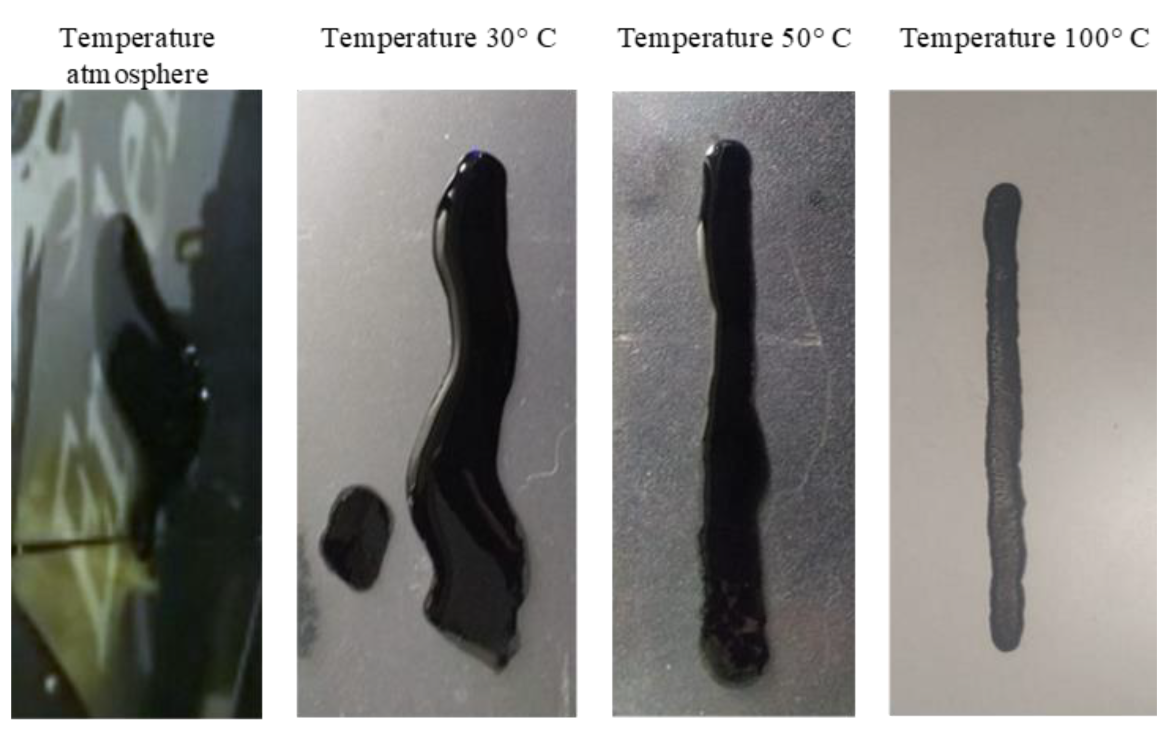
2.1. Carbon-Based Ink Preparation
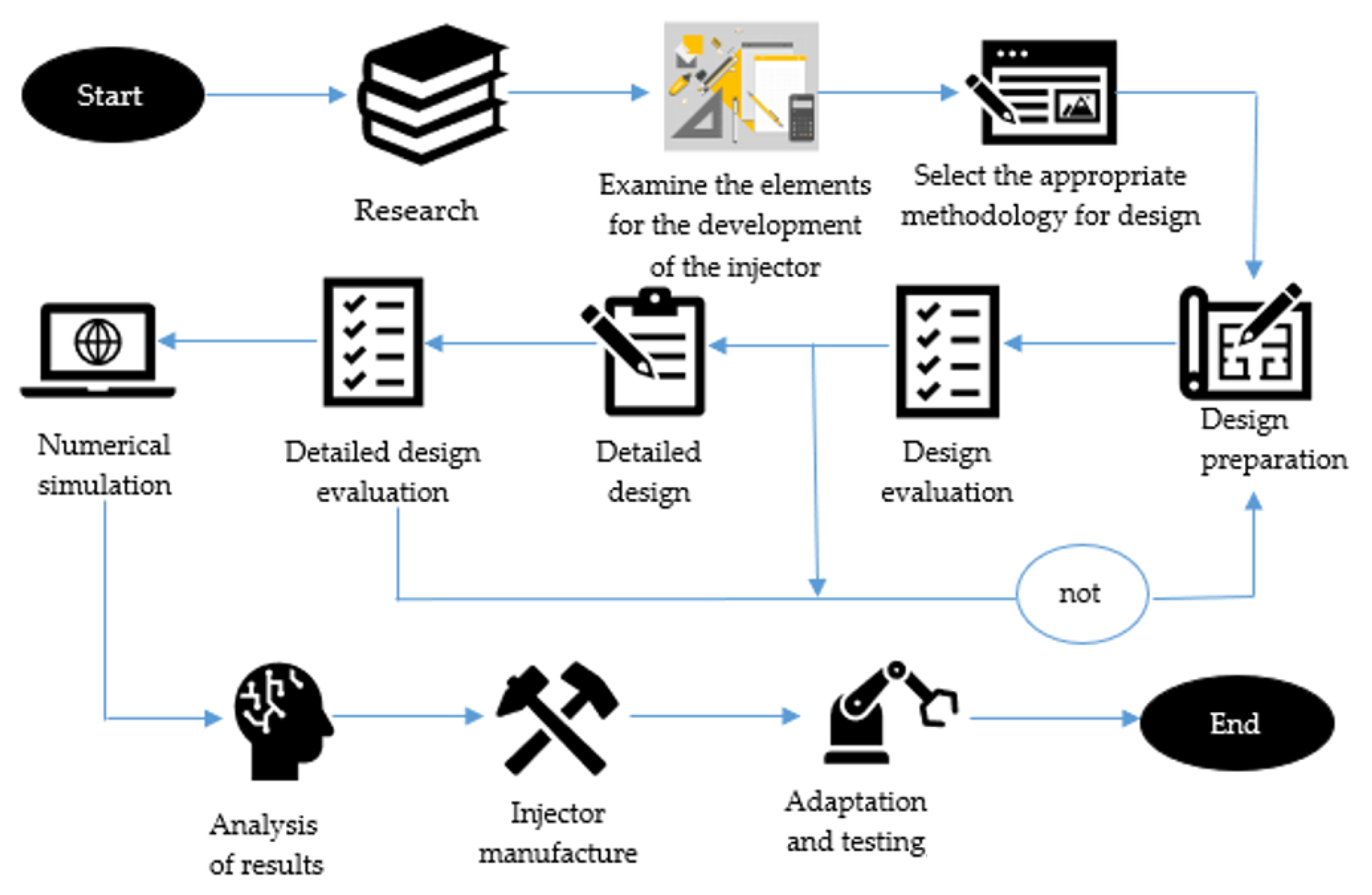
2.2. Methodology
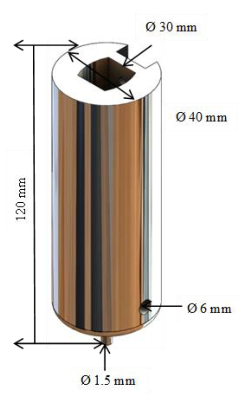
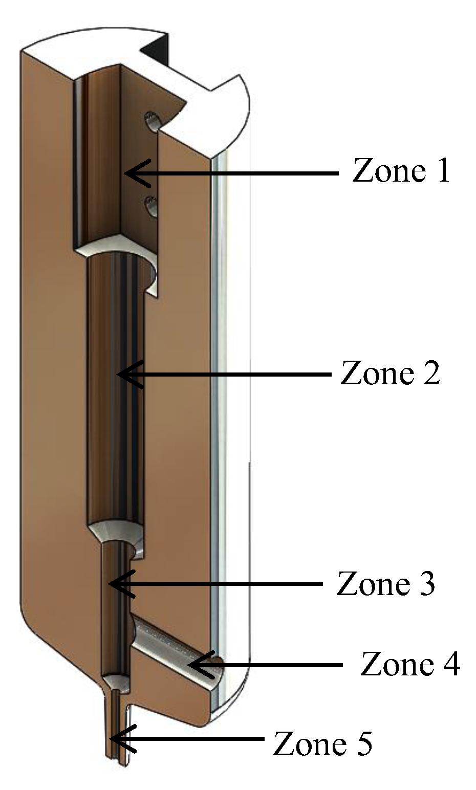
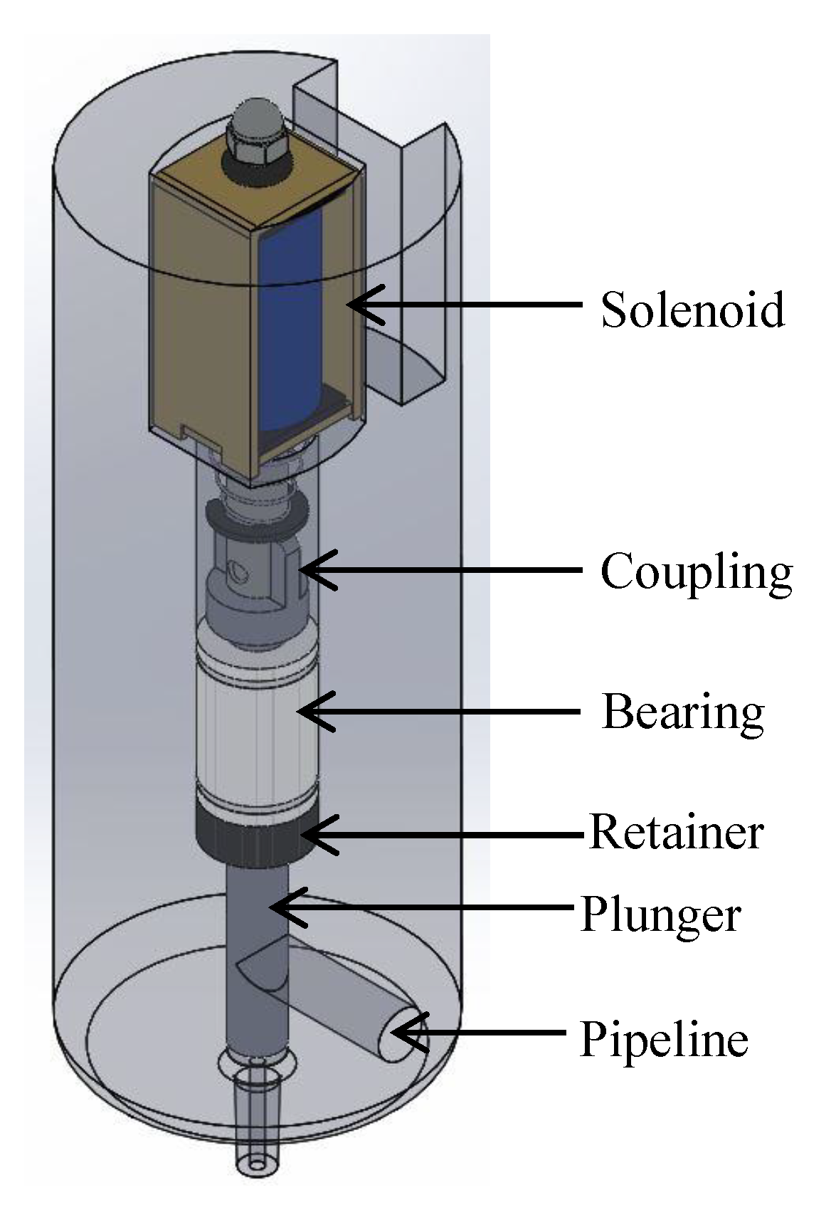
2.3. Detailed Design
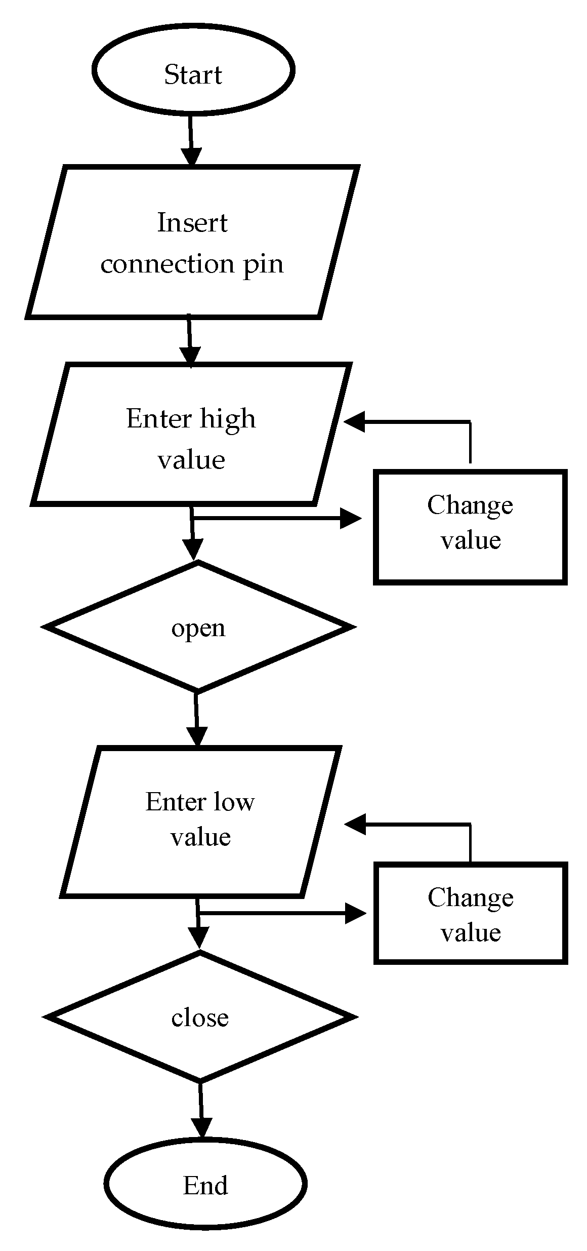
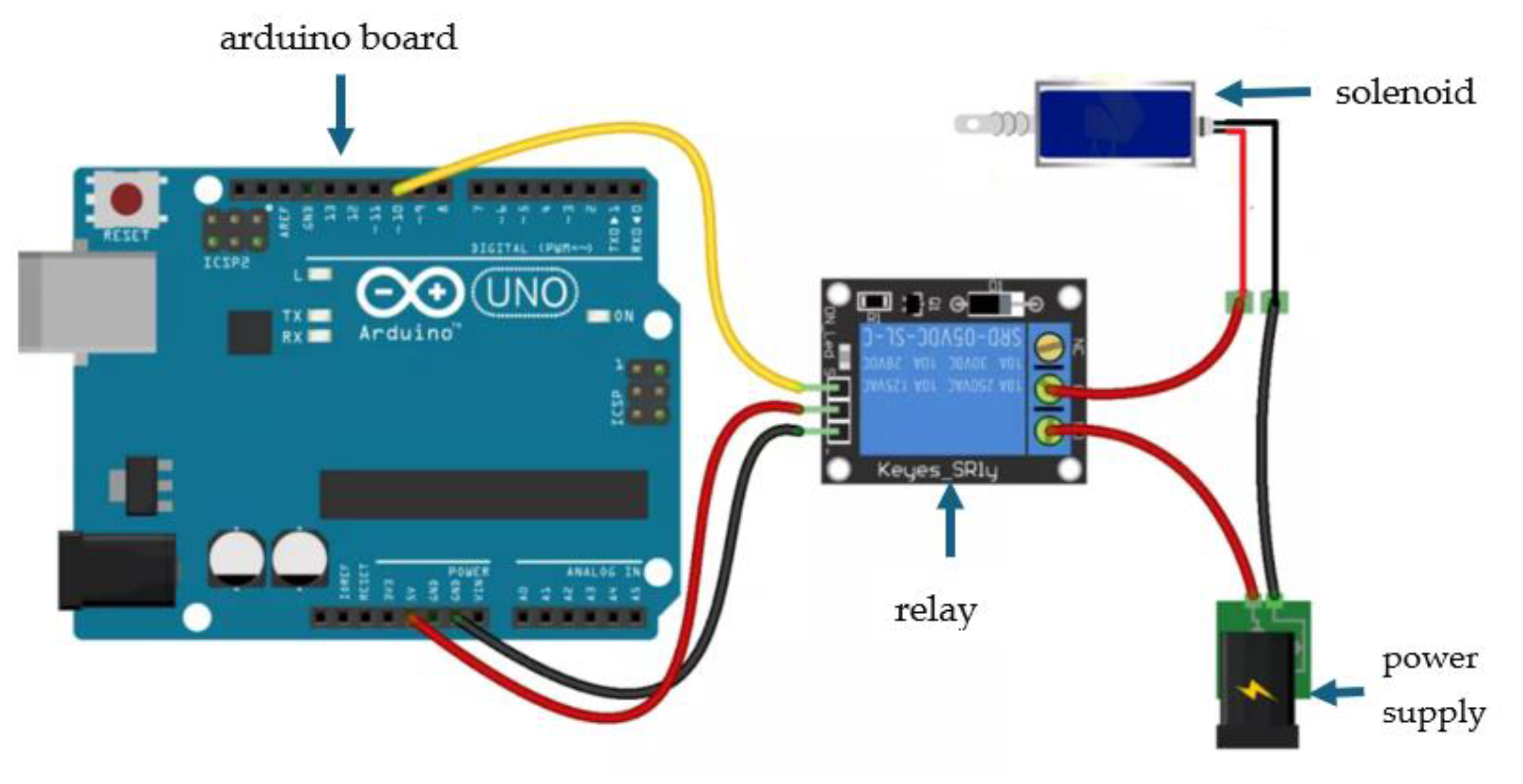
2.4. Solenoid Control
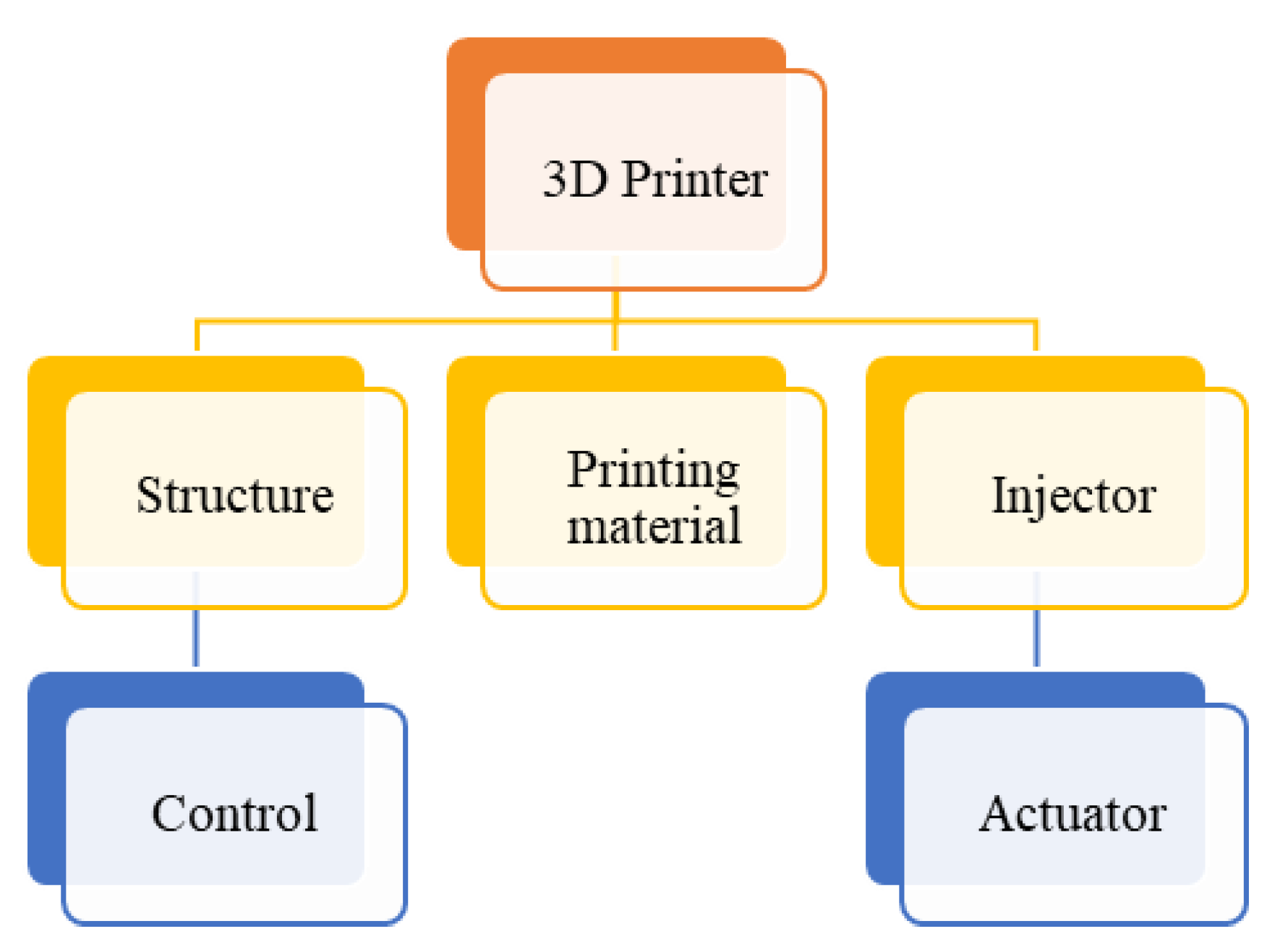
2.5. Injector Design
3. Results
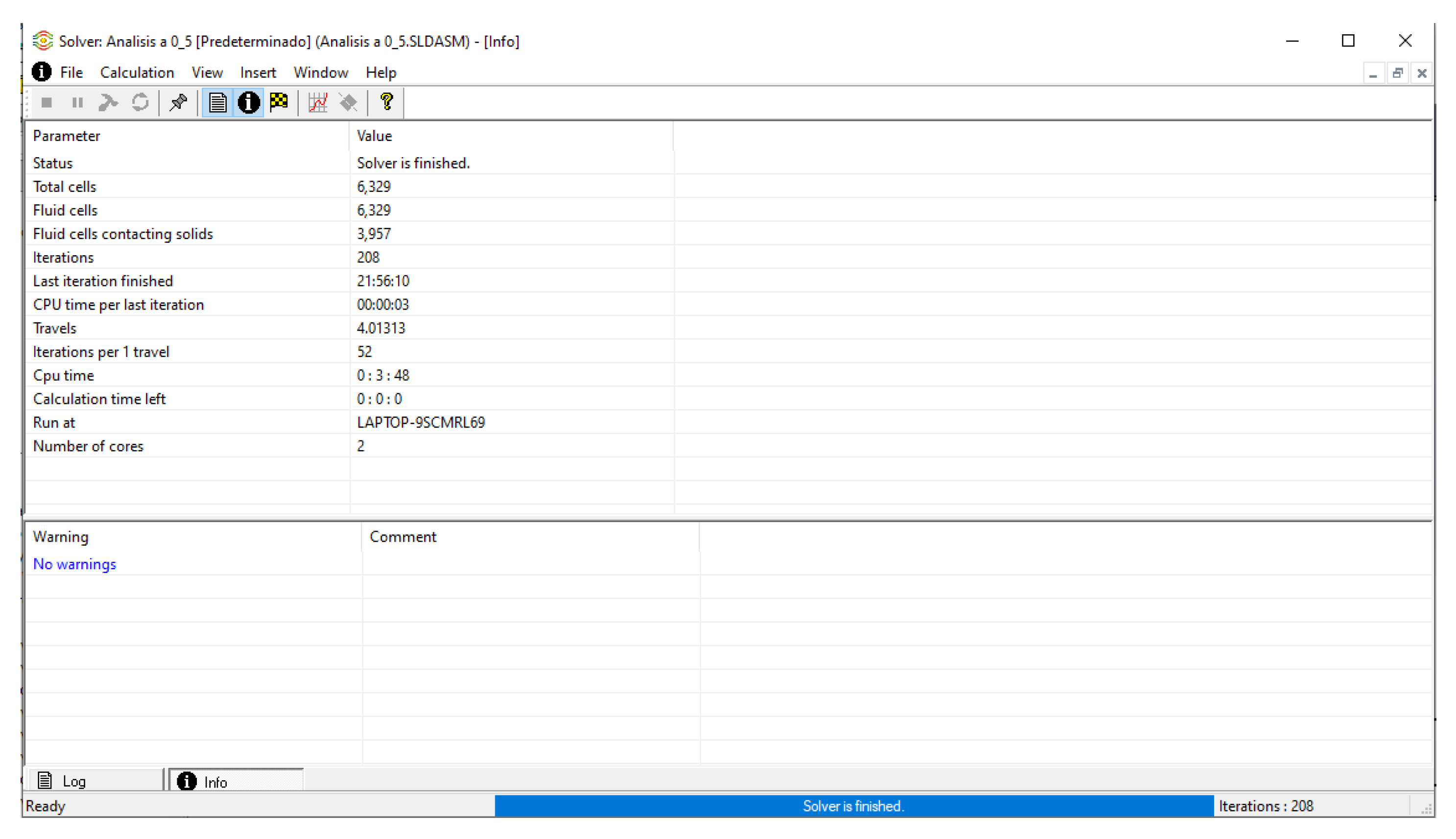
3.1. Computational Fluid Dynamics Analysis
3.1.1. Pressure
3.1.2. Velocity
3.1.3. Vorticity
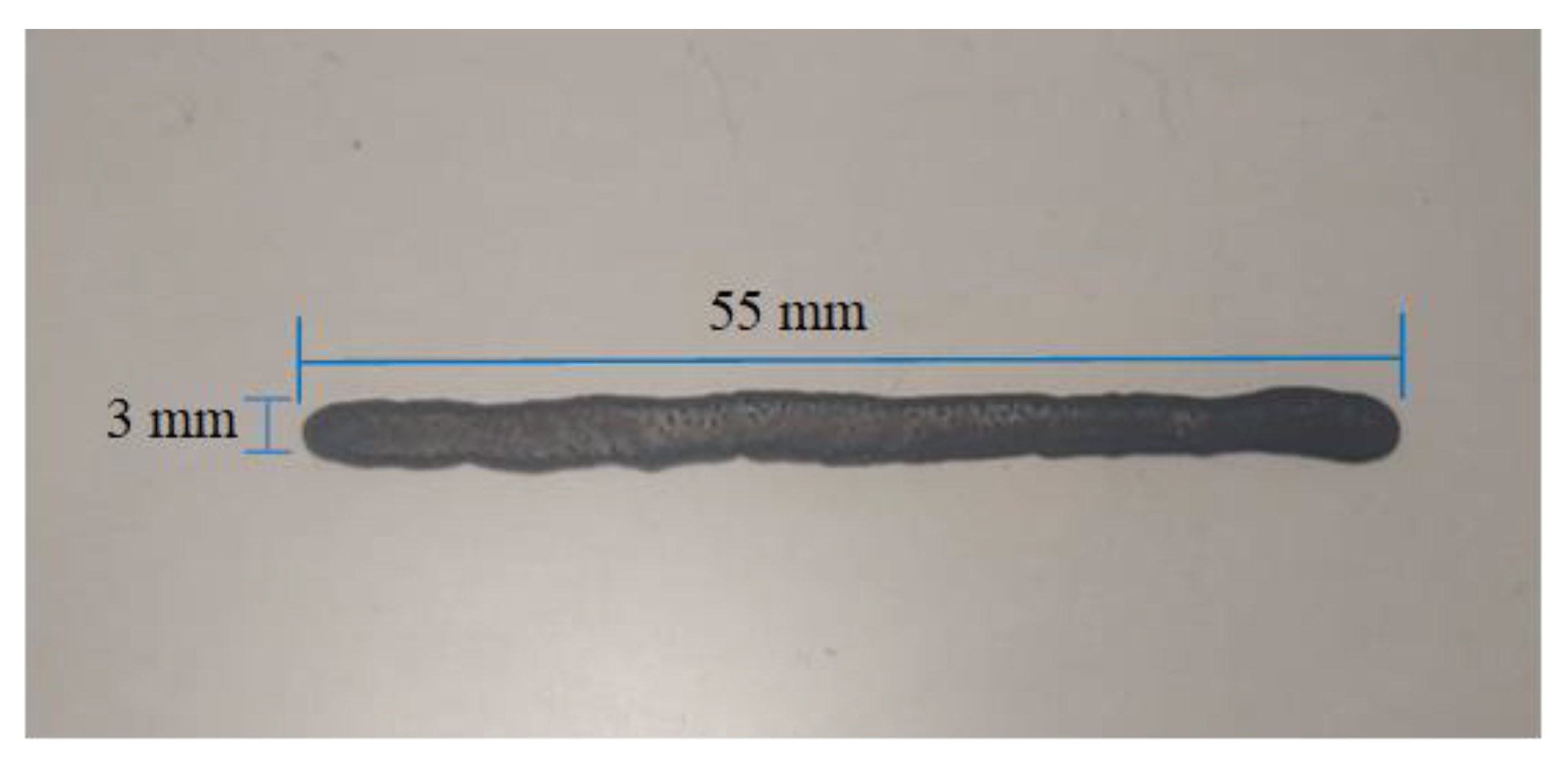
3.2. Experimental Results
4. Conclusions
Author Contributions
Funding
Institutional Review Board Statement
Informed Consent Statement
Data Availability Statement
Acknowledgments
Conflicts of Interest
References
- Berman, B. 3-D printing: The new industrial revolution. Bus. Horiz. 2012, 55, 155–162. [Google Scholar] [CrossRef]
- Thilmany, J. A new kind of design. Mech. Eng. 2009, 131, 36–40. [Google Scholar] [CrossRef]
- Sánchez, J. Impresoras 3D la nueva era tecnológica. Tecnol. Sist. 2019, 1, 1–13. [Google Scholar]
- Campo, M.; Cortes, A.; Jiménez, A.; Moriche, R.; Prolongo, S.G.; Ureña, A. Optimización de una tinta de resina termoestable con nanotubos de carbono para impresión por tecnologías de inyección. Asoc. Española Mater. Compuestos 2017, 2, 139–143. [Google Scholar]
- Liu, Z.; Zhang, M.; Bhandari, B.; Wang, Y. 3D printing: Printing precision and application in food sector. Trends Food Sci. Technol. 2017, 69, 83–94. [Google Scholar] [CrossRef]
- Do, A.-V.; Khorsand, B.; Geary, S.M.; Salem, A.K. 3D printing of scaffolds for tissue regeneration applications. Adv. Health Mater. 2015, 4, 1742–1762. [Google Scholar] [CrossRef] [PubMed]
- Jordan, J. 3D Printing; The Massachusetts Institute of Technology: Cambridge, MA, USA, 2019. [Google Scholar]
- Bandyopadhyay, A.; Bose, S.; Das, S. Impresión 3D de biomateriales. Boletín MRS 2015, 40, 108–115. [Google Scholar] [CrossRef]
- Wang, J.; Goyanes, A.; Gaisford, S.; Basit, A.W. Stereolithographic (SLA) 3D printing of oral modified-release dosage forms. Int. J. Pharm. 2016, 503, 207–212. [Google Scholar] [CrossRef] [PubMed]
- Fina, F.; Goyanes, A.; Gaisford, S.; Basit, A.W. Selective laser sintering (SLS) 3D printing of medicines. Int. J. Pharm. 2017, 529, 285–293. [Google Scholar] [CrossRef] [PubMed]
- Billiet, T.; Gevaert, E.; De Schryver, T.; Cornelissen, M.; Dubruel, P. The 3D printing of gelatin methacrylamide cell-laden tissue-engineered constructs with high cell viability. Biomaterials 2014, 35, 49–62. [Google Scholar] [CrossRef] [PubMed]
- Ozbolat, I.; Chen, H.; Yu, Y. Development of “Multi-arm Bioprinter” for hybrid biofabrication of tissue engineering constructs. Robot. Comput.-Integr. Manuf. 2014, 30, 295–304. [Google Scholar] [CrossRef]
- Lu, L.; Zheng, J.; Mishra, S. A model-based layer-to-layer control algorithm for ink-jet 3D printing. In Dynamic Systems and Control Conference; American Society of Mechanical Engineers: New York, NY, USA, 2014. [Google Scholar] [CrossRef]
- Cooley, P.W.; Wallace, D.B.; Antohe, B.V. Applications of ink-jet printing technology to BioMEMS and microfluidic systems. Adv. Mater. 2002, 7, 33–39. [Google Scholar] [CrossRef]
- Saadi, M.A.S.R.; Maguire, A.; Pottackal, N.T.; Thakur, S.H.; Ikram, M.M.; Hart, A.J.; Ajayan, P.M.; Rahman, M.M. Direct ink writing: A 3D printing technology for diverse materials. Adv. Mater. 2022, 34, e2108855. [Google Scholar] [CrossRef] [PubMed]
- Detamornrat, U.; McAlister, E.; Hutton, A.R.J.; Larrañeta, E.; Donnelly, R.F. The role of 3D printing technology in microengineering of microneedles. Small 2022, 18, e2106392. [Google Scholar] [CrossRef] [PubMed]
- Remaggi, G.; Zaccarelli, A.; Elviri, L. 3D Printing Technologies in Biosensors Production: Recent Developments. Chemosensors 2022, 10, 65. [Google Scholar] [CrossRef]
- Goh, G.L.; Dikshit, V.; Koneru, R.; Peh, Z.K.; Lu, W.; Yeong, W.Y. Fabrication of design-optimized multifunctional safety cage with conformal circuits for drone using hybrid 3D printing technology. Int. J. Adv. Manuf. Technol. 2022, 120, 2573–2586. [Google Scholar] [CrossRef]
- Dou, R.; Tang, W.; Hu, K.; Wang, L. Ceramic paste for space stereolithography 3D printing technology in microgravity environment. J. Eur. Ceram. Soc. 2022, 42, 3968–3975. [Google Scholar] [CrossRef]
- Young, A.; Le, L.; Kong, D.; Henderson, M.; Zunino, J.L., III; Fuchs, B.E. Inkjet-Printed Flexible Electronic Components from Graphene Oxide. U.S. Patent US20120170171A1, 5 July 2012. [Google Scholar]
- Jang, J.; Lee, S. Micropatterning of Graphene Using Inkjet Printing and Its Flexible Thin Film Electrode. Korean Patent KR20130075512A, 5 July 2013. [Google Scholar]
- Jeong, J. The Fabrication of Graphene Electrodes by Inkjet Printing and Its Transparent Thin Film Speaker Application. Korean Patent No. KR101251216B1, 26 September 2011. [Google Scholar]
- Worsley, M.; Duoss, E.; Kuntz, J.; Spadaccini, C.; Zhu, C. “System and method for 3d printing of aerogels”. U.S. Patent US20160067891A1, 3 August 2014. [Google Scholar]
- Shahrubudin, N.; Lee, T.; Ramlan, R. An Overview on 3D Printing Technology: Technological, Materials, and Applications. Procedia Manuf. 2019, 35, 1286–1296. [Google Scholar] [CrossRef]


| Plunger Distance | |
|---|---|
| 0.5 mm | 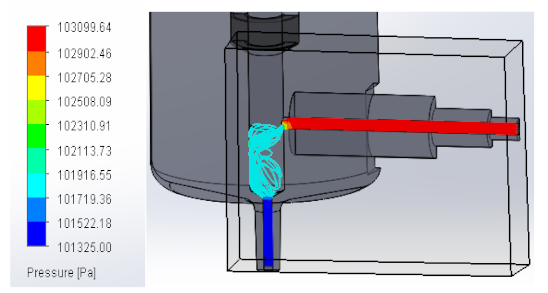 |
| 1 mm | 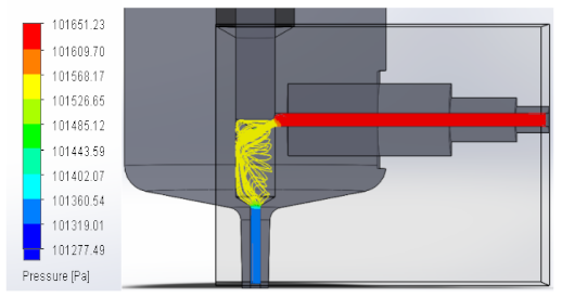 |
| 1.5 mm | 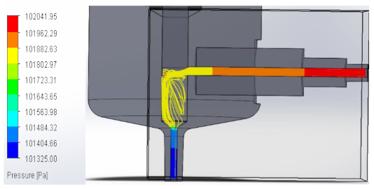 |
| 2 mm |  |
| Plunger Distance | |
|---|---|
| 0.5 mm |  |
| 1 mm | 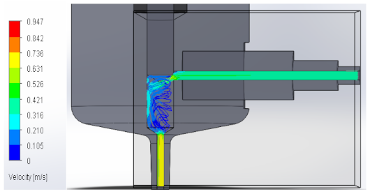 |
| 1.5 mm |  |
| 2 mm | 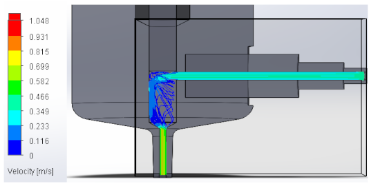 |
| Plunger Distance | |
|---|---|
| 0.5 mm |  |
| 1 mm | 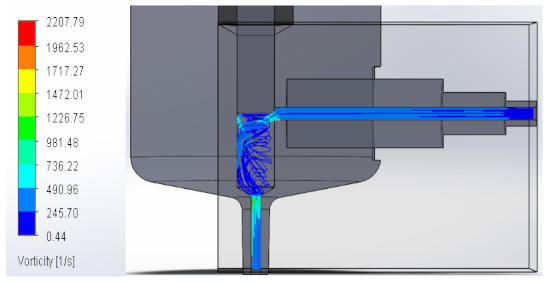 |
| 1.5 mm | 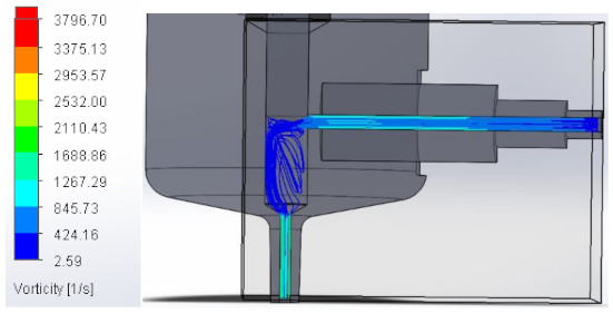 |
| 2 mm | 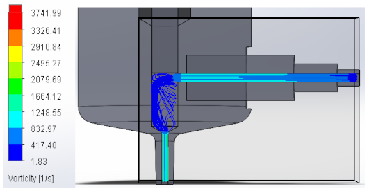 |
| Test | Plunger Distance | Velocity (ms) | Comment |
|---|---|---|---|
| 1 | 2 mm | 50 | The solenoid with this speed worked very fast. Because of this, carbon nanotube ink had a lot of turbulence and accumulation. |
| 2 | 2 mm | 100 | The turbulence decreased, there was not much expansion of the ink, and the flow was continuous. |
| 3 | 2 mm | 150 | Because the velocity decreased, there was no longer turbulence at the ink outlet. Therefore, there was no spreading when it is ejected. |
| 4 | 2 mm | 200 | The ink control improved, the solenoid had slower movement, and the ink was constant without turbulence. |
| 5 | 2 mm | 250 | The movement of the solenoid with this velocity presented better control of the ink, a constant thread was observed, and there was no turbulence at the outlet or spreading of the ink. |
Disclaimer/Publisher’s Note: The statements, opinions and data contained in all publications are solely those of the individual author(s) and contributor(s) and not of MDPI and/or the editor(s). MDPI and/or the editor(s) disclaim responsibility for any injury to people or property resulting from any ideas, methods, instructions or products referred to in the content. |
© 2023 by the authors. Licensee MDPI, Basel, Switzerland. This article is an open access article distributed under the terms and conditions of the Creative Commons Attribution (CC BY) license (https://creativecommons.org/licenses/by/4.0/).
Share and Cite
Ortega-Gutiérrez, A.; Escobar-Flores, J.E.; Grave-Capistrán, M.A.; López-Perrusquia, N.; Doñu-Ruiz, M.A.; Oropeza-Osornio, A.; Torres-SanMiguel, C.R. Conceptual Design and Numerical Validation of a Carbon-Based Ink Injector. Materials 2023, 16, 6545. https://doi.org/10.3390/ma16196545
Ortega-Gutiérrez A, Escobar-Flores JE, Grave-Capistrán MA, López-Perrusquia N, Doñu-Ruiz MA, Oropeza-Osornio A, Torres-SanMiguel CR. Conceptual Design and Numerical Validation of a Carbon-Based Ink Injector. Materials. 2023; 16(19):6545. https://doi.org/10.3390/ma16196545
Chicago/Turabian StyleOrtega-Gutiérrez, Arleth, Job Eli Escobar-Flores, Mario Alberto Grave-Capistrán, Noé López-Perrusquia, Marco Antonio Doñu-Ruiz, Armando Oropeza-Osornio, and Christopher René Torres-SanMiguel. 2023. "Conceptual Design and Numerical Validation of a Carbon-Based Ink Injector" Materials 16, no. 19: 6545. https://doi.org/10.3390/ma16196545