


Microwave-Assisted Synthesis as a Promising Tool for the Preparation of Materials Containing Defective Carbon Nanostructures: Implications on Properties and Applications


Abstract
:1. Introduction
2. Defects and Their Structural Variation
- One-dimensional (1D) line defects (e.g., dislocation).
- Two-dimensional (2D) planar defects (e.g., grain boundary).
- Three-dimensional (3D) volume defects (e.g., spatial lattice disorder).
3. Heteroatom Doping and Structural Defects of CNs with Relevance in Electrocatalysis and Electrochemistry
- i.
- ii.
- Pyridinic–like N is an atom that combines with two C atoms, enriching the aromatic ring with one p electron (p–type).
- Pyrrolic–like N is an atom that bonds to two C atoms, sharing two p electrons with the π system (n–type).
- Graphitic–like N (quaternary) in the graphene layer (in the six–membered ring) is substituted for one C atom (n–type).

| Heteroatom Doping | Substrates | Methods | Carbon Nanostructures | Concentration of Doping Elements | Nature of the Bonding Environment | Significant Properties | Applications | Ref. |
|---|---|---|---|---|---|---|---|---|
| Nitrogen | Collagen | Thermal treatment Acid treatment | N–OLC | 7.5 at. % N | Pyridinic N Pyrrolic N | Excellent operation stability | ORR catalysis Fuel cells | [114] |
| Acetonitrile | Pyrolysis | N–CNO | 4.0 at. % N | Pyridinic N Pyrrolic N Graphitic N | Long–term stability | ORR catalysis Nitride sensor | [155] | |
| Graphene Acetonitrile | CVD | N–Graphene | 4.0 at. % N | Pyrrolic N SW defects | High concentrations of defects | Supercapacitor | [55] | |
| Graphene Melamine | Thermal treatment | N–Graphene | 3.7 at. % N | Pyridinic N Pyrrolic N Graphitic N | High current and power density | ORR, OER, HER catalysis | [156] | |
| Melamine L–cysteine | Polymerization Pyrolysis | N–Graphene nanoribbons | 20 at. % N (800 °C) 5.9 at. % N (1000 °C) | Pyridinic N Graphitic N | Bifunctional electrocatalytic activity Excellent cycling stability | ORR and OER catalysis Zn–air batteries | [81] | |
| GO oxidant | Post-modification | N,O–GON | 3.4 at. % N | Pyrrolic N Pyridinic N | High corrosion resistance High selectivity H2O2 | ORR catalysis | [137] | |
| CNT Ionic liquid | Carbonization Post–modification | CNT/porous carbon (Core–sheath) | 4.6 at. % N 1.1 at. % S 5.4 at. % O | Pyridinic N Pyrrolic N Graphitic N | Durability and tolerance towards methanol | ORR catalysis | [157] | |
| Aminated–ND particles | Thermal treatment | N–CNO | 1.0 at. % N | Pyridinic N Pyrrolic N Graphitic N | Homogenous distributions of defects and active N sites | Electrocatalysis Catalytic activity towards H2O2 | [48,134] | |
| SiO2, DCD, APTES, ZIF–8, Zn(NO3)·6H2O | Inorganic synthesis Thermal treatment Etching SiO2 | N–HPC | 1.2 at. % N | Monovacancy coupled pyridinic N Graphitic N | Hierarchical porosity SBET = 3151.1 m2/g | ORR catalysis Zn-air batteries | [151] | |
| Boron | ND particles Amorphous boron | Thermal treatment | B–CNO | 0.76–3.21 at. % B | Substitutional B (B-C) Planar BC3 nanodomain | High crystallinity Excellent long–term charge/discharge stability | Catalysis Electrochemical capacitors | [34,120] |
| ND particles Boric acid | Thermal treatment | B–CNO CNO | 0.82–3.31 wt. % B | Boron atom cluster B4C Substitutional B (B-C) | σ = 1.62 1/Ωcm σ = 0.80 1/Ωcm | ORR catalysis | [69] | |
| GO, Boric acid | Ultrasonic treatment Hydrothermal reaction | B–rGO | 16.2 at. % B | Substitutional B (B-C) BCO2; BC2O | The lowest onset potential for B–doped graphene (0.83 V vs. RHE) | ORR catalysis | [158] | |
| Multi-heteroatoms | CNT, IL, silica | Post-modification Thermal treatment | N,S,F–CNT | Total N,S,F 8.8 wt. % | Pyridinic N Pyrrolic N Graphitic N | High durability Superior tolerance towards poisons | ORR catalysis Alkaline fuel cells | [157] |
| Solid graphite rod N2 atmosphere Amorphous boron | Arc-discharge evaporation | CNT N,B–CNT | - 0.5 at. % N 0.5 at. % B 1 at. % B and 1 at. % N | - Graphitic N N on edges and in topological defects Point substitutional defects C–B and C–N | σ(T)/σ(Tr) = 163 S/cm σ(T)/σ(Tr) = 184 S/cm Charge carriers: 3 × 1018 cm−3 σ(T)/σ(Tr) = 314 S/cm σ(T)/σ(Tr) = 493 S/cm Charge carriers: 1 × 1021 cm−3 | Conductors Magnetoconductors | [159] | |
| Melamine Phosphoric acid | Thermal treatment | g–P–C3N4 | 2.69–5.0 at. % N 0.40–3.34 at. % P | C defect coupled with N doping | High graphitization Edge defects | ORR catalysis | [160] | |
| ND Boric acid | Thermal treatment | N–B–CNO | 8.0 at. % B 7.4 at. % N | Substitutional B (B–C) BC3; BCO2; BC2O Pyridinic N Pyrrolic N Graphitic N; B–N | High degree of defects | ORR catalysis | [161] |
- i.
- micropores allow more active sites into the electrolyte;
- ii.
- mesopores can facilitate the mass transport in the catalyst layer;
- iii.
- macropores ensure the catalyst’s long–term stability [49].
4. MW–Assisted Synthesis for the Preparation and Modification of Materials Containing d-CNs
4.1. Definition of MW–Assisted Synthesis
- i.
- contactless heating;
- ii.
- a direct transfer of energy to the reactants;
- iii.
- independence from heat convection;
- iv.
- rapid heating rates, easy control of irradiation parameters;
- v.
- selectivity of heating;
- vi.
- the possibility of conducting the reaction locally and volumetrically.
- Top-down methods, which include the transformation of solid materials into carbon nanomaterials.
- Bottom-up methods, which include the preparation of carbon nanomaterials from liquid or gaseous carbonaceous precursors.
4.2. MW-Assisted Synthesis for the Preparation and Modification of d–CNs: Implications on Properties and Applications
| Defective CNs | Materials Containing d–CNs | Methods | Experimental Conditions | Applications | Significant Properties | Refs. |
|---|---|---|---|---|---|---|
| Pristine d-CNs | d–G (hydrogel) | MW–assisted hydrothermal synthesis | P = 800 W; t = 5 min | Supercapacitors | Cs = 340 F/g (j = 0.5 A/g) | [186] |
| N,S–GO | MW–assisted synthesis | P = 800 W; t = 5 min | Supercapacitors Universal: aqueous, non–aqueous, ionic electrolytes | Cs = 460 F/g (j = 1 A/g) Cs = 810 F/g (j = 3 A/g) | [118] | |
| S–rGO | MW–assisted synthesis | T = 140 °C; t = 30 min | Supercapacitors | Cs = 238 F/g | [187] | |
| rGO N,B–rGO | Chemical synthesis MW–assisted synthesis | P = 700 W; t = 40 s | EMI shielding devices | σ = 21.4 S/m σ = 124.4 S/m | [170] | |
| rGO (porous) | MW–assisted synthesis | P = 700 W; T = 180 °C; t = 6 min | Supercapacitors | Cs = 568 F/g (j = 1 A/g) | [188] | |
| rGO | IL–assisted MW synthesis | P = 700 W; t = 15 s | Supercapacitors | Cs = 135 F/g; Em = 58 Wh/kg; Pm = 246 kW/kg | [189] | |
| d–CNT | MW hydrogen plasma processing | P = 200 W t = 30 and 60 min | Vacuum electron sources | jemission = 10.36 mA/cm2 | [106] | |
| GO/g–C3N4 | Ultrasonic–MW–assisted synthesis | P = 700 W; t = 5 min | Photocatalytic H2 evolution | Photocatalytic H2-production rate 224.6 μm/h; GO electron collector and transporter | [190] | |
| GO/g–C3N4 | MW–assisted synthesis Chemical treatment | P = 700 W; t = 5 min | Supercapacitors | SBET = 353 m2/g; Cs = 113 F/g SBET = 686 m2/g; Cs = 169 F/g | [191] | |
| N–PGF | MW–assisted synthesis | P = 800 W; t = 4 s | Supercapacitors | Cs = 272.6 F/g; E = 2.3 mW h/cm; P = 0.42 W/cm | [192] | |
| Hybrid materials containing d-CNs | CNT/Fe2O3 | CVD; MW hydrothermal synthesis | T = 160 °C; t = 6 h | Lithium–Ion Battery Electrodes | C = 900 mAh/g | [193] |
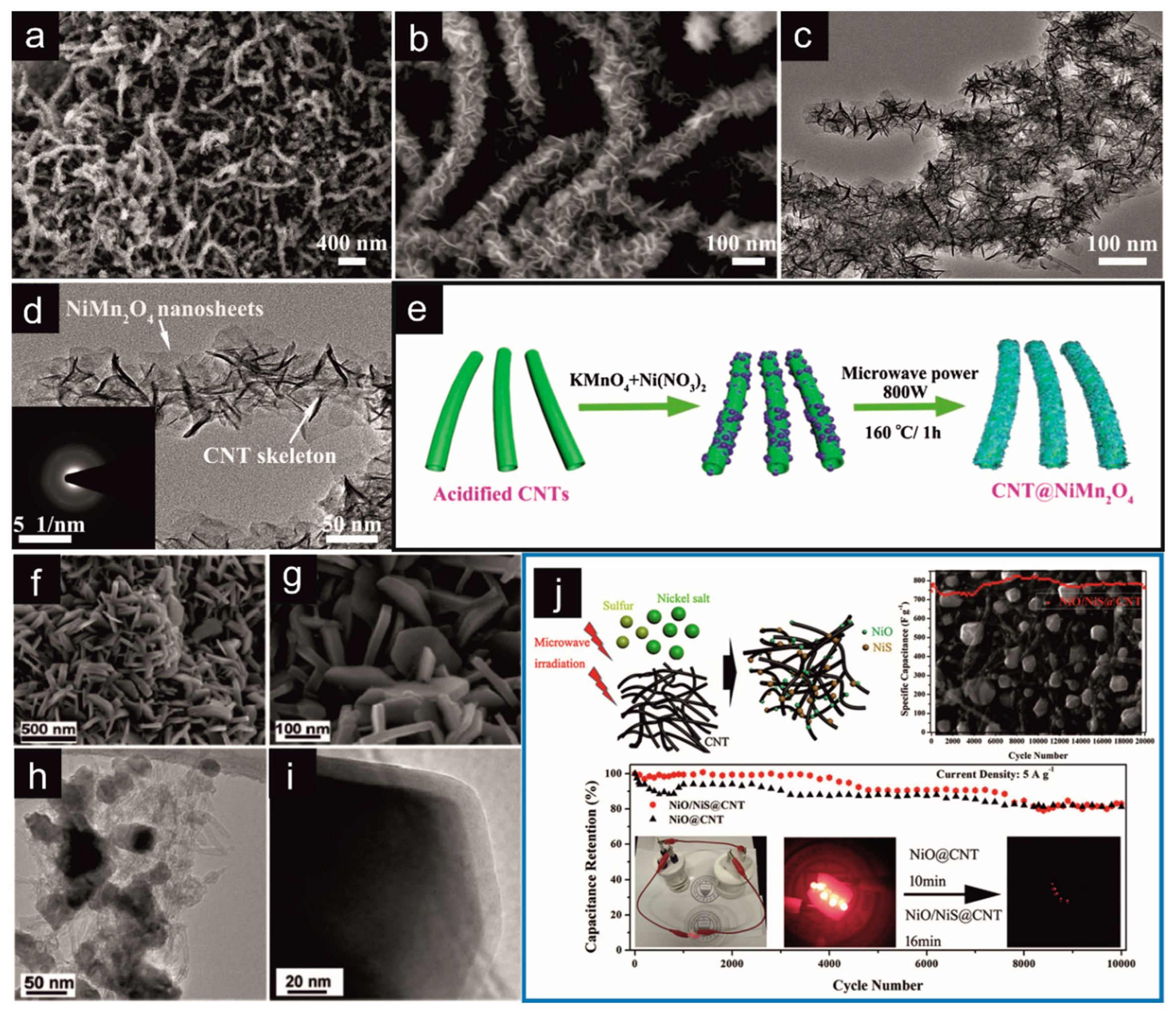
| CNT/NiMn2O4 | MW–assisted hydrothermal synthesis | P = 800 W; T = 160 °C; t = 1 h | Supercapacitors | Cs = 916 F/g (j = 1 A/g) Em = 36.5 Wh/kg; Pm = 800 W/kg | [194] | |
| MWCNT/CoMoO4 | MW–assisted solid-state synthesis | P = 480–720 W; t = 8 min | Supercapacitors | Cs = 170 F/g (j = 0.1 A/g) | [195] | |
| NiS@CNT/NiO | MW–assisted solid-state synthesis | P = 1000 W; t = 60 s | Supercapacitors | Cs = 810 F/g (j = 1 A/g) | [196] | |
| rGO/NiS | MW–assisted hydrothermal synthesis | P = 700 W; t = 4 min | Supercapacitors Solid–state Supercapacitors | Cs = 1746 F/g (j = 1 A/g) Cs = 14.20 F/g; Em = 7.1 Wh/kg; Pm = 1836 W/kg | [197] | |
| rGO/Fe3O4 NPs rGO/Fe3O4 ONCs | Chemical exfoliation MW–assisted synthesis | P = 700 W; t = 1.25–1.75 min | Lithium–Ion Battery Electrodes | C = 1050 mA h/g (j = 100 mA/g) C = 1625 mA h/g (j = 100 mA/g) | [185] | |
| rGO/CNT/NiNP | Thermal exfoliation MW–assisted synthesis | P = 700 W; t = 5 min | Lithium–Ion Battery Electrodes | C = 648.2 mA h/g (j = 100 mA/g) C = 282.4 mA h/g (j = 100 mA/g) | [198] | |
| rGO/NiO/Co3O4 | MW–assisted synthesis | P = 700 W; t = 45 s | Supercapacitors | Cs = 910 F/g (v = 20 mV/s) SBET = 99.5 m2/g | [199] | |
| rGO/CoAl–LDH | MW–assisted reflux synthesis | P = 1000 W; T = 100 °C; t = 2 h | Supercapacitors | Cs = 772 F/g (j = 1 A/g) Em = 22.7 Wh/kg; Pm = 230 kW/kg | [200] | |
| rGO/NiAl–LDH | MW–assisted reflux synthesis | P = 1000 W; T = 100 °C; t = 2 h | Supercapacitors | Cs = 1630 F/g (j = 1 A/g) SBET = 121.2 m2/g | [201] | |
| rGO/NiMoO4 | MW–solvothermal synthesis Thermal annealing | P = 200 W; T = 115 °C; t = 25 min | Supercapacitors | Cs = 1274 F/g (j = 1 A/g) SBET = 50.8 m2/g Cs = 800 F/g (j = 1 A/g) SBET = 30.9 m2/g | [202] | |
| N–G/NiS | MW–assisted synthesis | P = 336 W; t = 18 min | Supercapacitors | Cs = 1468 F/g (j = 1 A/g) Em = 66.6 Wh/kg; Pm = 405.8 W/kg | [203] | |
| rGO/MnCo2O4 | Exfoliation MW–assisted synthesis | P = 900 W; t = 45–70 s | Supercapacitors | Cs = 562 F/g (v = 20 mV/s) | [204] | |
| G/α–MoO3 | MW–assisted synthesis | P = 700 W; t = 7 min | Supercapacitors | Cs = 483 F/g (j = 1 A/g) | [205] | |
| rGO/CoSe2 | MW–assisted synthesis Thermal annealing | P = 700 W; t = 7 min | Supercapacitors LED | Cs = 761 F/g (j = 1 A/g) Em = 43.1 Wh/kg | [206] | |
| G/Co9S8 | MW–assisted hydrothermal synthesis | P = 700 W; T = 160 °C; t = 30 min; p = 8 × 10⁶ Pa | Supercapacitors | Cs = 1150 F/g (v = 5 mV/s) | [67] | |
| rGO/MnN | MW–assisted synthesis | P = 900 W; t = 1 min | Sodium ion batteries Supercapacitors | C = 16 mAh/g Cs = 639.2 F/g (v = 10 mV/s) | [207] | |
| rGO/MnO2 | Conventional synthesis MW–assisted synthesis | P = 700 W; t = 2 min; 21 cycles | Supercapacitors | Cs = 140 F/g (j = 1 A/g) | [208] | |
| rGO/Pd | MW–assisted synthesis | P = 810 W; t = 90–125 s | Electrocatalysis (Ethanol Oxidation) | Catalytic activity 10.2 mA/cm2 (Pd) | [209] | |
| S–rGO/NiFeS2 | MW–assisted synthesis | P = 800 W; t = 3 min | Supercapacitors | Cs = 1073 F/g (j = 1 A/g) Em = 45.7 Wh/kg; Pm = 222 W/kg | [210] | |
| 3D Pd–E–PG | MW–assisted synthesis | P = 700 ÷ 900 W; t = 30 ÷ 60 s | H2 storage CO oxidation | H2 5.4 wt. % 100% CO conversion < 300 °C | [211] | |
| NiF–G/SimonK | MW–hydrothermal synthesis | P = 700 W; t = 1 h; p = 100 bar | Supercapacitors | Cs = 836 F/g (j = 1 A/g) | [212] | |
| G/NiCoS | MW–assisted synthesis | P = 600 W; t = 20 min | Supercapacitors | Cs = 1186 F/g (j = 1 A/g) Em = 46.4 Wh/kg | [213] | |
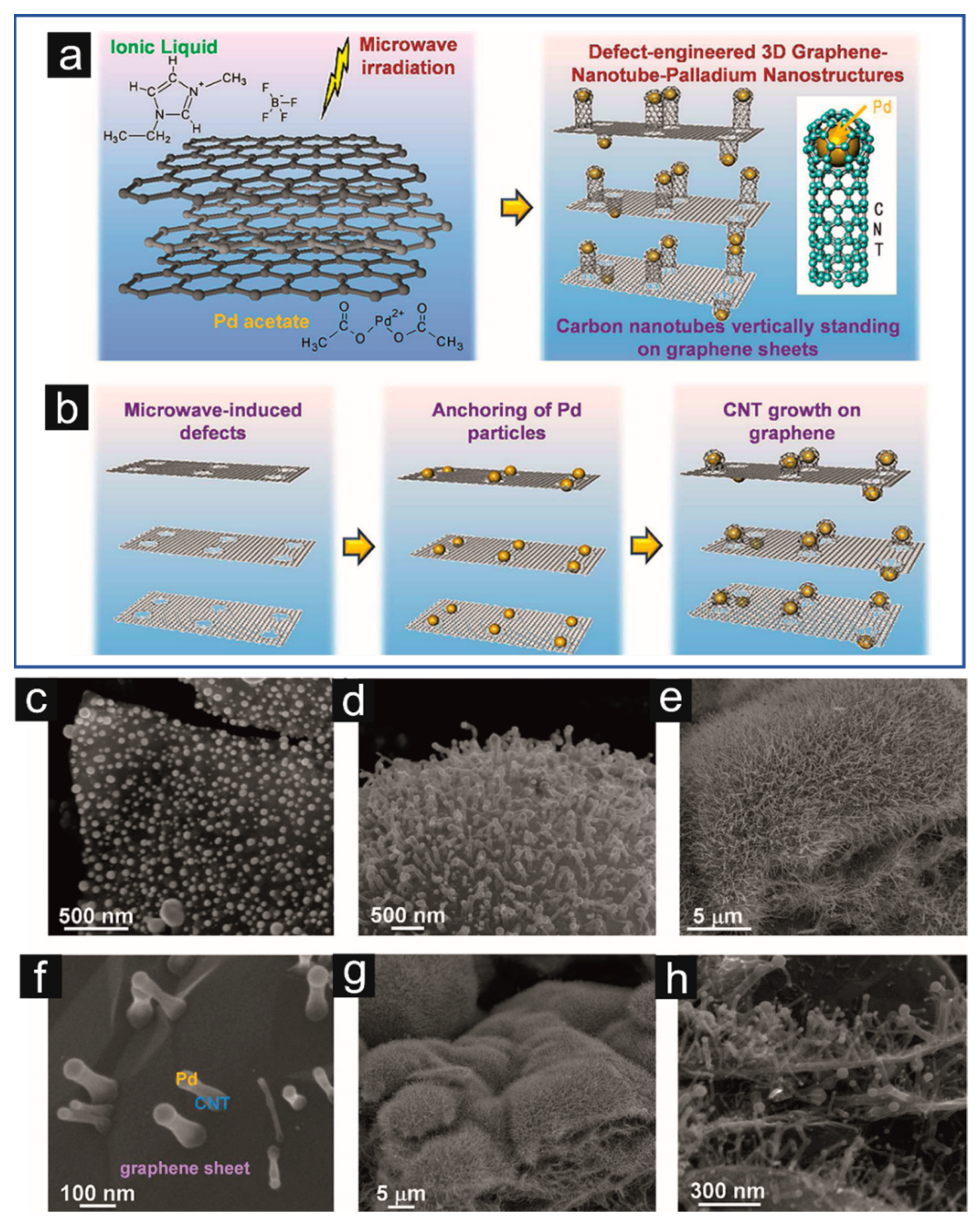
| G/CNT/Pd | IL–assisted MW synthesis | P = 700 W; t = 10 min | Energy storage systems | Cs = 1615 F/g (v = 10 mV/s) | [214] | |
| CMK-3/CNT | Hard–templating method MW–assisted synthesis | P = 700 W; t = 30 s | Supercapacitors | Cs = 315 F/g (j = 1 A/g) | [68] |
4.3. MW-Assisted Synthesis for the Preparation of Hybrid Materials Containing d–CNs: Implications on Properties and Applications
5. Concluding Remarks
Author Contributions
Funding
Institutional Review Board Statement
Informed Consent Statement
Data Availability Statement
Conflicts of Interest
References
- Gu, W.; Yushin, G. Review of Nanostructured Carbon Materials for Electrochemical Capacitor Applications: Advantages and Limitations of Activated Carbon, Carbide-Derived Carbon, Zeolite-Templated Carbon, Carbon Aerogels, Carbon Nanotubes, Onion-like Carbon, and Graphene: Nanostructured Carbon Materials for Electrochemical Capacitor Applications. Wiley Interdiscip. Rev. Energy Environ. 2014, 3, 424–473. [Google Scholar] [CrossRef]
- Al-Jumaili, A.; Alancherry, S.; Bazaka, K.; Jacob, M. Review on the Antimicrobial Properties of Carbon Nanostructures. Materials 2017, 10, 1066. [Google Scholar] [CrossRef] [PubMed]
- Bobrowska, D.M.; Olejnika, P.; Echegoyen, L.; Brzezinska, M. Onion-like Carbon Nanostructures: An Overview of Bio-Applications. Curr. Med. Chem. 2018, 25, 6896–6914. [Google Scholar] [CrossRef] [PubMed]
- Yu, S.-S.; Zheng, W.-T. Effect of N/B Doping on the Electronic and Field Emission Properties for Carbon Nanotubes, Carbon Nanocones, and Graphene Nanoribbons. Nanoscale 2010, 2, 1069. [Google Scholar] [CrossRef] [PubMed]
- Rathinavel, S.; Priyadharshini, K.; Panda, D. A Review on Carbon Nanotube: An Overview of Synthesis, Properties, Functionalization, Characterization, and the Application. Mater. Sci. Eng. B 2021, 268, 115095. [Google Scholar] [CrossRef]
- Robertson, J. Comparison of Diamond-like Carbon to Diamond for Applications. Phys. Status Solidi A 2008, 205, 2233–2244. [Google Scholar] [CrossRef]
- Robertson, J. Electronic Structure of Diamond-like Carbon. Diam. Relat. Mater. 1997, 6, 212–218. [Google Scholar] [CrossRef]
- Mykhailiv, O.; Zubyk, H.; Plonska-Brzezinska, M.E. Carbon Nano-Onions: Unique Carbon Nanostructures with Fascinating Properties and Their Potential Applications. Inorganica Chim. Acta 2017, 468, 49–66. [Google Scholar] [CrossRef]
- Yang, G.; Li, L.; Lee, W.B.; Ng, M.C. Structure of Graphene and Its Disorders: A Review. Sci. Technol. Adv. Mater. 2018, 19, 613–648. [Google Scholar] [CrossRef]
- Gao, X.; Liu, H.; Wang, D.; Zhang, J. Graphdiyne: Synthesis, Properties, and Applications. Chem. Soc. Rev. 2019, 48, 908–936. [Google Scholar] [CrossRef]
- Khan, K.; Tareen, A.K.; Iqbal, M.; Shi, Z.; Zhang, H.; Guo, Z. Novel Emerging Graphdiyne Based Two Dimensional Materials: Synthesis, Properties and Renewable Energy Applications. Nano Today 2021, 39, 101207. [Google Scholar] [CrossRef]
- Zhao, Y.; Yang, N.; Yu, R.; Zhang, Y.; Zhang, J.; Li, Y.; Wang, D. Unique Structural Advances of Graphdiyne for Energy Applications. EnergyChem 2020, 2, 100041. [Google Scholar] [CrossRef]
- Liu, H.; Zhang, L.; Yan, M.; Yu, J. Carbon Nanostructures in Biology and Medicine. J. Mater. Chem. B 2017, 5, 6437–6450. [Google Scholar] [CrossRef]
- Hu, Y.; Shenderova, O.A.; Hu, Z.; Padgett, C.W.; Brenner, D.W. Carbon Nanostructures for Advanced Composites. Rep. Prog. Phys. 2006, 69, 1847–1895. [Google Scholar] [CrossRef]
- Kumar, S.; Rani, R.; Dilbaghi, N.; Tankeshwar, K.; Kim, K.-H. Carbon Nanotubes: A Novel Material for Multifaceted Applications in Human Healthcare. Chem. Soc. Rev. 2017, 46, 158–196. [Google Scholar] [CrossRef] [PubMed]
- Sek, S.; Breczko, J.; Plonska-Brzezinska, M.E.; Wilczewska, A.Z.; Echegoyen, L. STM-Based Molecular Junction of Carbon Nano-Onion. ChemPhysChem 2013, 14, 96–100. [Google Scholar] [CrossRef] [PubMed]
- Wang, M.-S.; Golberg, D.; Bando, Y. Carbon “Onions” as Point Electron Sources. ACS Nano 2010, 4, 4396–4402. [Google Scholar] [CrossRef] [PubMed]
- Keller, N.; Maksimova, N.I.; Roddatis, V.V.; Schur, M.; Mestl, G.; Butenko, Y.V.; Kuznetsov, V.L.; Schlögl, R. The Catalytic Use of Onion-like Carbon Materials for Styrene Synthesis by Oxidative Dehydrogenation of Ethylbenzene. Angew. Chem. Int. Ed. Engl. 2002, 41, 1885–1888. [Google Scholar] [CrossRef]
- Su, D.; Maksimova, N.I.; Mestl, G.; Kuznetsov, V.L.; Keller, V.; Schlögl, R.; Keller, N. Oxidative Dehydrogenation of Ethylbenzene to Styrene over Ultra-Dispersed Diamond and Onion-like Carbon. Carbon 2007, 45, 2145–2151. [Google Scholar] [CrossRef]
- Feng, Y.; Jiang, J.; Xu, Y.; Wang, S.; An, W.; Chai, Q.; Prova, U.H.; Wang, C.; Huang, G. Biomass Derived Diverse Carbon Nanostructure for Electrocatalysis, Energy Conversion and Storage. Carbon 2023, 211, 118105. [Google Scholar] [CrossRef]
- Plonska-Brzezinska, M.E.; Echegoyen, L. Carbon Nano-Onions for Supercapacitor Electrodes: Recent Developments and Applications. J. Mater. Chem. A 2013, 1, 13703. [Google Scholar] [CrossRef]
- Lee, J.; Lee, T.H.; Jang, H.W.; Park, H.S. Chemical Modification of Ordered/Disordered Carbon Nanostructures for Metal Hosts and Electrocatalysts of Lithium-Air Batteries. InfoMat 2022, 4, e12268. [Google Scholar] [CrossRef]
- Bobrowska, D.M.; Brzezinski, K.; Echegoyen, L.; Plonska-Brzezinska, M.E. A New Perspective on Carbon Nano-Onion/Nickel Hydroxide/Oxide Composites: Physicochemical Properties and Application in Hybrid Electrochemical Systems. Fuller. Nanotub. Carbon Nanostruct. 2017, 25, 193–203. [Google Scholar] [CrossRef]
- Luszczyn, J.; Plonska-Brzezinska, M.E.; Palkar, A.; Dubis, A.T.; Simionescu, A.; Simionescu, D.T.; Kalska-Szostko, B.; Winkler, K.; Echegoyen, L. Small Noncytotoxic Carbon Nano-Onions: First Covalent Functionalization with Biomolecules. Chem. Eur. J. 2010, 16, 4870–4880. [Google Scholar] [CrossRef]
- Breczko, J.; Plonska-Brzezinska, M.E.; Echegoyen, L. Electrochemical Oxidation and Determination of Dopamine in the Presence of Uric and Ascorbic Acids Using a Carbon Nano-Onion and Poly(Diallyldimethylammonium Chloride) Composite. Electrochim. Acta 2012, 72, 61–67. [Google Scholar] [CrossRef]
- Huang, Y.; Liang, J.; Chen, Y. The Application of Graphene Based Materials for Actuators. J. Mater. Chem. 2012, 22, 3671. [Google Scholar] [CrossRef]
- Sohouli, E.; Ghalkhani, M.; Zargar, T.; Joseph, Y.; Rahimi-Nasrabadi, M.; Ahmadi, F.; Plonska-Brzezinska, M.E.; Ehrlich, H. A New Electrochemical Aptasensor Based on Gold/Nitrogen-Doped Carbon Nano-Onions for the Detection of Staphylococcus aureus. Electrochim. Acta 2022, 403, 139633. [Google Scholar] [CrossRef]
- Bobrowska, D.M.; Brzezinski, K.; Plonska-Brzezinska, M.E. PEGylated Carbon Nano-Onions Composite as a Carrier of Polyphenolic Compounds: A Promising System for Medical Applications and Biological Sensors. Colloid Interface Sci. Commun. 2017, 21, 6–9. [Google Scholar] [CrossRef]
- Banerjee, A.N. Graphene and Its Derivatives as Biomedical Materials: Future Prospects and Challenges. Interface Focus 2018, 8, 20170056. [Google Scholar] [CrossRef]
- Bartelmess, J.; Giordani, S. Carbon Nano-Onions (Multi-Layer Fullerenes): Chemistry and Applications. Beilstein J. Nanotechnol. 2014, 5, 1980–1998. [Google Scholar] [CrossRef]
- Ghosh, M.; Sonkar, S.K.; Saxena, M.; Sarkar, S. Carbon Nano-Onions for Imaging the Life Cycle of Drosophila Melanogaster. Small 2011, 7, 3170–3177. [Google Scholar] [CrossRef] [PubMed]
- Giordani, S.; Bartelmess, J.; Frasconi, M.; Biondi, I.; Cheung, S.; Grossi, M.; Wu, D.; Echegoyen, L.; O’Shea, D.F. NIR Fluorescence Labelled Carbon Nano-Onions: Synthesis, Analysis and Cellular Imaging. J. Mater. Chem. B 2014, 2, 7459–7463. [Google Scholar] [CrossRef] [PubMed]
- Regulska, E.; Olejnik, P.; Zubyk, H.; Czyrko-Horczak, J.; Chaur, M.N.; Tomczykowa, M.; Butsyk, O.; Brzezinski, K.; Echegoyen, L.; Plonska-Brzezinska, M.E. Nanostructural Catalyst: Metallophthalocyanine and Carbon Nano-Onion with Enhanced Visible-Light Photocatalytic Activity towards Organic Pollutants. RSC Adv. 2020, 10, 10910–10920. [Google Scholar] [CrossRef] [PubMed]
- Mykhailiv, O.; Brzezinski, K.; Sulikowski, B.; Olejniczak, Z.; Gras, M.; Lota, G.; Molina-Ontoria, A.; Jakubczyk, M.; Echegoyen, L.; Plonska-Brzezinska, M.E. Boron-Doped Polygonal Carbon Nano-Onions: Synthesis and Applications in Electrochemical Energy Storage. Chem. Eur. J. 2017, 23, 7132–7141. [Google Scholar] [CrossRef] [PubMed]
- Simon, P.; Gogotsi, Y. Materials for Electrochemical Capacitors. Nat. Mater. 2008, 7, 845–854. [Google Scholar] [CrossRef] [PubMed]
- Li, D.; Jia, Y.; Chang, G.; Chen, J.; Liu, H.; Wang, J.; Hu, Y.; Xia, Y.; Yang, D.; Yao, X. A Defect-Driven Metal-Free Electrocatalyst for Oxygen Reduction in Acidic Electrolyte. Chem 2018, 4, 2345–2356. [Google Scholar] [CrossRef]
- Jiang, Y.; Yang, L.; Sun, T.; Zhao, J.; Lyu, Z.; Zhuo, O.; Wang, X.; Wu, Q.; Ma, J.; Hu, Z. Significant Contribution of Intrinsic Carbon Defects to Oxygen Reduction Activity. ACS Catal. 2015, 5, 6707–6712. [Google Scholar] [CrossRef]
- Tang, C.; Wang, H.-F.; Chen, X.; Li, B.-Q.; Hou, T.-Z.; Zhang, B.; Zhang, Q.; Titirici, M.-M.; Wei, F. Topological Defects in Metal-Free Nanocarbon for Oxygen Electrocatalysis. Adv. Mater. 2016, 28, 6845–6851. [Google Scholar] [CrossRef]
- Banham, D.; Ye, S.; Pei, K.; Ozaki, J.; Kishimoto, T.; Imashiro, Y. A Review of the Stability and Durability of Non-Precious Metal Catalysts for the Oxygen Reduction Reaction in Proton Exchange Membrane Fuel Cells. J. Power Sources 2015, 285, 334–348. [Google Scholar] [CrossRef]
- Zheng, Y.; Jiao, Y.; Zhu, Y.; Cai, Q.; Vasileff, A.; Li, L.H.; Han, Y.; Chen, Y.; Qiao, S.-Z. Molecule-Level g-C3N4 Coordinated Transition Metals as a New Class of Electrocatalysts for Oxygen Electrode Reactions. J. Am. Chem. Soc. 2017, 139, 3336–3339. [Google Scholar] [CrossRef]
- Jia, Y.; Jiang, K.; Wang, H.; Yao, X. The Role of Defect Sites in Nanomaterials for Electrocatalytic Energy Conversion. Chem 2019, 5, 1371–1397. [Google Scholar] [CrossRef]
- Yan, X.; Jia, Y.; Yao, X. Defects on Carbons for Electrocatalytic Oxygen Reduction. Chem. Soc. Rev. 2018, 47, 7628–7658. [Google Scholar] [CrossRef] [PubMed]
- Chung, H.T.; Cullen, D.A.; Higgins, D.; Sneed, B.T.; Holby, E.F.; More, K.L.; Zelenay, P. Direct Atomic-Level Insight into the Active Sites of a High-Performance PGM-Free ORR Catalyst. Science 2017, 357, 479–484. [Google Scholar] [CrossRef] [PubMed]
- Zhou, H.; Sheng, X.; Xiao, J.; Ding, Z.; Wang, D.; Zhang, X.; Liu, J.; Wu, R.; Feng, X.; Jiang, L. Increasing the Efficiency of Photocatalytic Reactions via Surface Microenvironment Engineering. J. Am. Chem. Soc. 2020, 142, 2738–2743. [Google Scholar] [CrossRef] [PubMed]
- Bai, S.; Jiang, W.; Li, Z.; Xiong, Y. Surface and Interface Engineering in Photocatalysis. ChemNanoMat 2015, 1, 223–239. [Google Scholar] [CrossRef]
- Li, J.; Abbas, S.U.; Wang, H.; Zhang, Z.; Hu, W. Recent Advances in Interface Engineering for Electrocatalytic CO2 Reduction Reaction. Nano-Micro Lett. 2021, 13, 216. [Google Scholar] [CrossRef] [PubMed]
- Chen, S.; Liu, X.; Xiong, J.; Mi, L.; Song, X.-Z.; Li, Y. Defect and Interface Engineering in Metal Sulfide Catalysts for the Electrocatalytic Nitrogen Reduction Reaction: A Review. J. Mater. Chem. A 2022, 10, 6927–6949. [Google Scholar] [CrossRef]
- Mykhailiv, O.; Zubyk, H.; Brzezinski, K.; Gras, M.; Lota, G.; Gniadek, M.; Romero, E.; Echegoyen, L.; Plonska-Brzezinska, M.E. Improvement of the Structural and Chemical Properties of Carbon Nano-onions for Electrocatalysis. ChemNanoMat 2017, 3, 583–590. [Google Scholar] [CrossRef]
- Liu, D.; Ni, K.; Ye, J.; Xie, J.; Zhu, Y.; Song, L. Carbon Nanomaterials: Tailoring the Structure of Carbon Nanomaterials toward High-End Energy Applications. Adv. Mater. 2018, 30, 1870371. [Google Scholar] [CrossRef]
- Zhang, C.; Shen, W.; Guo, K.; Xiong, M.; Zhang, J.; Lu, X. A Pentagonal Defect-Rich Metal-Free Carbon Electrocatalyst for Boosting Acidic O2 Reduction to H2O2 Production. J. Am. Chem. Soc. 2023, 145, 11589–11598. [Google Scholar] [CrossRef]
- Miller, J.R.; Simon, P. The Chalkboard: Fundamentals of Electrochemical Capacitor Design and Operation. Electrochem. Soc. Interface 2008, 17, 31–32. [Google Scholar] [CrossRef]
- Simon, P.; Gogotsi, Y. Perspectives for Electrochemical Capacitors and Related Devices. Nat. Mater. 2020, 19, 1151–1163. [Google Scholar] [CrossRef] [PubMed]
- Largeot, C.; Portet, C.; Chmiola, J.; Taberna, P.-L.; Gogotsi, Y.; Simon, P. Relation between the Ion Size and Pore Size for an Electric Double-Layer Capacitor. J. Am. Chem. Soc. 2008, 130, 2730–2731. [Google Scholar] [CrossRef]
- Wu, X.; Yu, M.; Liu, J.; Li, S.; Zhang, X. Sp3-Defect and Pore Engineered Carbon Framework for High Energy Density Supercapacitors. J. Power Sources 2020, 464, 228203. [Google Scholar] [CrossRef]
- Chen, J.; Han, Y.; Kong, X.; Deng, X.; Park, H.J.; Guo, Y.; Jin, S.; Qi, Z.; Lee, Z.; Qiao, Z.; et al. The Origin of Improved Electrical Double-Layer Capacitance by Inclusion of Topological Defects and Dopants in Graphene for Supercapacitors. Angew. Chem. Int. Ed. 2016, 55, 13822–13827. [Google Scholar] [CrossRef] [PubMed]
- Jourdain, V.; Bichara, C. Current Understanding of the Growth of Carbon Nanotubes in Catalytic Chemical Vapour Deposition. Carbon 2013, 58, 2–39. [Google Scholar] [CrossRef]
- Bacsa, R.R.; Laurent, C.; Peigney, A.; Bacsa, W.S.; Vaugien, T.; Rousset, A. High Specific Surface Area Carbon Nanotubes from Catalytic Chemical Vapor Deposition Process. Chem. Phys. Lett. 2000, 323, 566–571. [Google Scholar] [CrossRef]
- Yamamoto, G.; Shirasu, K.; Nozaka, Y.; Sato, Y.; Takagi, T.; Hashida, T. Structure–Property Relationships in Thermally-Annealed Multi-Walled Carbon Nanotubes. Carbon 2014, 66, 219–226. [Google Scholar] [CrossRef]
- Bom, D.; Andrews, R.; Jacques, D.; Anthony, J.; Chen, B.; Meier, M.S.; Selegue, J.P. Thermogravimetric Analysis of the Oxidation of Multiwalled Carbon Nanotubes: Evidence for the Role of Defect Sites in Carbon Nanotube Chemistry. Nano Lett. 2002, 2, 615–619. [Google Scholar] [CrossRef]
- Xu, X.; Xu, C.; Liu, J.; Jin, R.; Luo, X.; Shu, C.; Chen, H.; Guo, C.; Xu, L.; Si, Y. The Synergistic Effect of “Soft-Hard Template” to in Situ Regulate Mass Transfer and Defective Sites of Doped-Carbon Nanostructures for Catalysis of Oxygen Reduction. J. Alloys Compd. 2023, 939, 168782. [Google Scholar] [CrossRef]
- Benito, A.M.; Maniette, Y.; Muñoz, E.; Martínez, M.T. Carbon Nanotubes Production by Catalytic Pyrolysis of Benzene. Carbon 1998, 36, 681–683. [Google Scholar] [CrossRef]
- Lin, W.; Moon, K.-S.; Zhang, S.; Ding, Y.; Shang, J.; Chen, M.; Wong, C. Microwave Makes Carbon Nanotubes Less Defective. ACS Nano 2010, 4, 1716–1722. [Google Scholar] [CrossRef] [PubMed]
- Vázquez, E.; Prato, M. Carbon Nanotubes and Microwaves: Interactions, Responses, and Applications. ACS Nano 2009, 3, 3819–3824. [Google Scholar] [CrossRef] [PubMed]
- Mubarak, N.M.; Sahu, J.N.; Abdullah, E.C.; Jayakumar, N.S.; Ganesan, P. Single Stage Production of Carbon Nanotubes Using Microwave Technology. Diam. Relat. Mater. 2014, 48, 52–59. [Google Scholar] [CrossRef]
- Hong, E.H.; Lee, K.-H.; Oh, S.H.; Park, C.-G. Synthesis of Carbon Nanotubes Using Microwave Radiation. Adv. Funct. Mater. 2003, 13, 961–966. [Google Scholar] [CrossRef]
- Bulusheva, L.G.; Arkhipov, V.E.; Popov, K.M.; Sysoev, V.I.; Makarova, A.A.; Okotrub, A.V. Electronic Structure of Nitrogen- and Phosphorus-Doped Graphenes Grown by Chemical Vapor Deposition Method. Materials 2020, 13, 1173. [Google Scholar] [CrossRef] [PubMed]
- Masikhwa, T.M.; Madito, M.J.; Bello, A.; Lekitima, J.; Manyala, N. Microwave-Assisted Synthesis of Cobalt Sulphide Nanoparticle Clusters on Activated Graphene Foam for Electrochemical Supercapacitors. RSC Adv. 2017, 7, 20231–20240. [Google Scholar] [CrossRef]
- Yan, K.; Sun, X.; Ying, S.; Cheng, W.; Deng, Y.; Ma, Z.; Zhao, Y.; Wang, X.; Pan, L.; Shi, Y. Ultrafast Microwave Synthesis of Rambutan-like CMK-3/Carbon Nanotubes Nanocomposites for High-Performance Supercapacitor Electrode Materials. Sci. Rep. 2020, 10, 6227. [Google Scholar] [CrossRef]
- Lin, Y.; Zhu, Y.; Zhang, B.; Kim, Y.A.; Endo, M.; Su, D.S. Boron-Doped Onion-like Carbon with Enriched Substitutional Boron: The Relationship between Electronic Properties and Catalytic Performance. J. Mater. Chem. A 2015, 3, 21805–21814. [Google Scholar] [CrossRef]
- Plonska-Brzezinska, M.E.; Dubis, A.T.; Lapinski, A.; Villalta-Cerdas, A.; Echegoyen, L. Electrochemical Properties of Oxidized Carbon Nano-Onions: DRIFTS-FTIR and Raman Spectroscopic Analyses. ChemPhysChem 2011, 12, 2659–2668. [Google Scholar] [CrossRef]
- Xiao, B.; Boudou, J.P.; Thomas, K.M. Reactions of Nitrogen and Oxygen Surface Groups in Nanoporous Carbons under Inert and Reducing Atmospheres. Langmuir 2005, 21, 3400–3409. [Google Scholar] [CrossRef] [PubMed]
- Datsyuk, V.; Kalyva, M.; Papagelis, K.; Parthenios, J.; Tasis, D.; Siokou, A.; Kallitsis, I.; Galiotis, C. Chemical Oxidation of Multiwalled Carbon Nanotubes. Carbon 2008, 46, 833–840. [Google Scholar] [CrossRef]
- Plonska-Brzezinska, M.E.; Lapinski, A.; Wilczewska, A.Z.; Dubis, A.T.; Villalta-Cerdas, A.; Winkler, K.; Echegoyen, L. The Synthesis and Characterization of Carbon Nano-Onions Produced by Solution Ozonolysis. Carbon 2011, 49, 5079–5089. [Google Scholar] [CrossRef]
- Yang, D.-Q.; Sacher, E. Strongly Enhanced Interaction between Evaporated Pt Nanoparticles and Functionalized Multiwalled Carbon Nanotubes via Plasma Surface Modifications: Effects of Physical and Chemical Defects. J. Phys. Chem. C 2008, 112, 4075–4082. [Google Scholar] [CrossRef]
- Zschoerper, N.P.; Katzenmaier, V.; Vohrer, U.; Haupt, M.; Oehr, C.; Hirth, T. Analytical Investigation of the Composition of Plasma-Induced Functional Groups on Carbon Nanotube Sheets. Carbon 2009, 47, 2174–2185. [Google Scholar] [CrossRef]
- Liu, J.; Zubiri, M.R.I.; Vigolo, B.; Dossot, M.; Fort, Y.; Ehrhardt, J.-J.; McRae, E. Efficient Microwave-Assisted Radical Functionalization of Single-Wall Carbon Nanotubes. Carbon 2007, 45, 885–891. [Google Scholar] [CrossRef]
- Kuo, C.-Y. Comparison with As-Grown and Microwave Modified Carbon Nanotubes to Removal Aqueous Bisphenol A. Desalination 2009, 249, 976–982. [Google Scholar] [CrossRef]
- Deng, D.; Yu, L.; Pan, X.; Wang, S.; Chen, X.; Hu, P.; Sun, L.; Bao, X. Size Effect of Graphene on Electrocatalytic Activation of Oxygen. Chem. Commun. 2011, 47, 10016. [Google Scholar] [CrossRef]
- Liu, D.; Ni, K.; Ye, J.; Xie, J.; Zhu, Y.; Song, L. Tailoring the Structure of Carbon Nanomaterials toward High-End Energy Applications. Adv. Mater. 2018, 30, 1802104. [Google Scholar] [CrossRef]
- Kotakoski, J.; Krasheninnikov, A.V.; Kaiser, U.; Meyer, J.C. From Point Defects in Graphene to Two-Dimensional Amorphous Carbon. Phys. Rev. Lett. 2011, 106, 105505. [Google Scholar] [CrossRef]
- Yang, H.B.; Miao, J.; Hung, S.-F.; Chen, J.; Tao, H.B.; Wang, X.; Zhang, L.; Chen, R.; Gao, J.; Chen, H.M.; et al. Identification of Catalytic Sites for Oxygen Reduction and Oxygen Evolution in N-Doped Graphene Materials: Development of Highly Efficient Metal-Free Bifunctional Electrocatalyst. Sci. Adv. 2016, 2, e1501122. [Google Scholar] [CrossRef] [PubMed]
- Jia, Y.; Chen, J.; Yao, X. Defect Electrocatalytic Mechanism: Concept, Topological Structure and Perspective. Mater. Chem. Front. 2018, 2, 1250–1268. [Google Scholar] [CrossRef]
- Dresselhaus, M.S.; Jorio, A.; Souza Filho, A.G.; Saito, R. Defect characterization in graphene and carbon nanotubes using Raman spectroscopy. Phil. Trans. R. Soc. A. 2010, 368, 5355–5377. [Google Scholar] [CrossRef] [PubMed]
- Trevethan, T.; Latham, C.D.; Heggie, M.I.; Briddon, P.R.; Rayson, M.J. Vacancy Diffusion and Coalescence in Graphene Directed by Defect Strain Fields. Nanoscale 2014, 6, 2978–2986. [Google Scholar] [CrossRef] [PubMed]
- Li, Z.; Peng, H.; Liu, R.; Mo, Y.; Cao, B.; Lai, W.; Li, X.; Pan, L.; Chen, Y. Quantitative Assessment of Basal-, Edge- and Defect-Surfaces of Carbonaceous Materials and Their Influence on Electric Double-Layer Capacitance. J. Power Sources 2020, 457, 228022. [Google Scholar] [CrossRef]
- Wang, Y.; Zhu, Y.; Wu, H. Formation and Topological Structure of Three-Dimensional Disordered Graphene Networks. Phys. Chem. Chem. Phys. 2021, 23, 10290–10302. [Google Scholar] [CrossRef] [PubMed]
- Ma, J.; Alfè, D.; Michaelides, A.; Wang, E. Stone-Wales Defects in Graphene and Other Planar sp2-Bonded Materials. Phys. Rev. B 2009, 80, 033407. [Google Scholar] [CrossRef]
- Akhunova, A.K.; Galiakhmetova, L.K.; Baimova, J.A. The Effects of Dislocation Dipoles on the Failure Strength of Wrinkled Graphene from Atomistic Simulation. Appl. Sci. 2022, 13, 9. [Google Scholar] [CrossRef]
- Zhao, S.; Guo, Z.; Yang, J.; Wang, C.; Sun, B.; Wang, G. Nanoengineering of Advanced Carbon Materials for Sodium-Ion Batteries. Small 2021, 17, 2007431. [Google Scholar] [CrossRef]
- Pastor, E.; Sachs, M.; Selim, S.; Durrant, J.R.; Bakulin, A.A.; Walsh, A. Electronic Defects in Metal Oxide Photocatalysts. Nat. Rev. Mater. 2022, 7, 503–521. [Google Scholar] [CrossRef]
- Okuyama, Y.; Kurita, N.; Fukatsu, N. Defect Structure of Alumina-Rich Nonstoichiometric Magnesium Aluminate Spinel. Solid State Ion. 2006, 177, 59–64. [Google Scholar] [CrossRef]
- Frauenheim, T.; Blaudeck, P.; Stephan, U.; Jungnickel, G. Atomic Structure and Physical Properties of Amorphous Carbon and Its Hydrogenated Analogs. Phys. Rev. B 1993, 48, 4823–4834. [Google Scholar] [CrossRef] [PubMed]
- Cho, N.-H.; Krishnan, K.M.; Veirs, D.K.; Rubin, M.D.; Hopper, C.B.; Bhushan, B.; Bogy, D.B. Chemical Structure and Physical Properties of Diamond-like Amorphous Carbon Films Prepared by Magnetron Sputtering. J. Mater. Res. 1990, 5, 2543–2554. [Google Scholar] [CrossRef]
- Mounier, E.; Bertin, F.; Adamik, M.; Pauleau, Y.; Barna, P.B. Effect of the Substrate Temperature on the Physical Characteristics of Amorphous Carbon Films Deposited by d.c. Magnetron Sputtering. Diam. Relat. Mater. 1996, 5, 1509–1515. [Google Scholar] [CrossRef]
- Miller, D. Building a Project Work Breakdown Structure: Visualizing Objectives, Deliverables, Activities, and Schedules; ESI International Project Management Series; Auerbach Publications: Boca Raton, FL, USA, 2008; Volume 20085940, ISBN 978-1-4200-6969-3. [Google Scholar]
- Bandaru, P.R.; Yamada, H.; Narayanan, R.; Hoefer, M. Charge Transfer and Storage in Nanostructures. Mater. Sci. Eng. R Rep. 2015, 96, 1–69. [Google Scholar] [CrossRef]
- Bagge-Hansen, M.; Bastea, S.; Hammons, J.A.; Nielsen, M.H.; Lauderbach, L.M.; Hodgin, R.L.; Pagoria, P.; May, C.; Aloni, S.; Jones, A.; et al. Detonation Synthesis of Carbon Nano-Onions via Liquid Carbon Condensation. Nat. Commun. 2019, 10, 3819. [Google Scholar] [CrossRef] [PubMed]
- Moussa, G.; Matei Ghimbeu, C.; Taberna, P.-L.; Simon, P.; Vix-Guterl, C. Relationship between the Carbon Nano-Onions (CNOs) Surface Chemistry/Defects and Their Capacitance in Aqueous and Organic Electrolytes. Carbon 2016, 105, 628–637. [Google Scholar] [CrossRef]
- Deng, J.-H.; Cheng, L.; Wang, F.-J.; Yu, B.; Li, G.-Z.; Li, D.-J.; Cheng, G.-A. Ultralow Field Emission from Thinned, Open-Ended, and Defected Carbon Nanotubes by Using Microwave Hydrogen Plasma Processing. Appl. Surf. Sci. 2015, 324, 293–299. [Google Scholar] [CrossRef]
- Ferrari, A.C.; Meyer, J.C.; Scardaci, V.; Casiraghi, C.; Lazzeri, M.; Mauri, F.; Piscanec, S.; Jiang, D.; Novoselov, K.S.; Roth, S.; et al. Raman Spectrum of Graphene and Graphene Layers. Phys. Rev. Lett. 2006, 97, 187401. [Google Scholar] [CrossRef]
- Tuinstra, F.; Koenig, J.L. Raman Spectrum of Graphite. J. Chem. Phys. 1970, 53, 1126–1130. [Google Scholar] [CrossRef]
- Fowler, R.H.; Nordheim, L. Electron Emission in Intense Electric Fields. Proc. R. Soc. Lond. Ser. Contain. Pap. Math. Phys. Character 1928, 119, 173–181. [Google Scholar] [CrossRef]
- Borgohain, R.; Li, J.; Selegue, J.P.; Cheng, Y.-T. Electrochemical Study of Functionalized Carbon Nano-Onions for High-Performance Supercapacitor Electrodes. J. Phys. Chem. C 2012, 116, 15068–15075. [Google Scholar] [CrossRef]
- Portet, C.; Yushin, G.; Gogotsi, Y. Electrochemical Performance of Carbon Onions, Nanodiamonds, Carbon Black and Multiwalled Nanotubes in Electrical Double Layer Capacitors. Carbon 2007, 45, 2511–2518. [Google Scholar] [CrossRef]
- Liu, X.; Antonietti, M. Molten Salt Activation for Synthesis of Porous Carbon Nanostructures and Carbon Sheets. Carbon 2014, 69, 460–466. [Google Scholar] [CrossRef]
- Wang, J.-G.; Liu, H.; Zhang, X.; Li, X.; Liu, X.; Kang, F. Green Synthesis of Hierarchically Porous Carbon Nanotubes as Advanced Materials for High-Efficient Energy Storage. Small 2018, 14, 1703950. [Google Scholar] [CrossRef] [PubMed]
- Wang, P.; Ye, H.; Yin, Y.; Chen, H.; Bian, Y.; Wang, Z.; Cao, F.; Guo, Y. Fungi-Enabled Synthesis of Ultrahigh-Surface-Area Porous Carbon. Adv. Mater. 2019, 31, 1805134. [Google Scholar] [CrossRef] [PubMed]
- Pech, D.; Brunet, M.; Durou, H.; Huang, P.; Mochalin, V.; Gogotsi, Y.; Taberna, P.-L.; Simon, P. Ultrahigh-Power Micrometre-Sized Supercapacitors Based on Onion-like Carbon. Nat. Nanotechnol. 2010, 5, 651–654. [Google Scholar] [CrossRef]
- Zeiger, M.; Jäckel, N.; Aslan, M.; Weingarth, D.; Presser, V. Understanding Structure and Porosity of Nanodiamond-Derived Carbon Onions. Carbon 2015, 84, 584–598. [Google Scholar] [CrossRef]
- An, Y.; Li, C.; Sun, X.; Wang, K.; Su, F.; Liu, F.; Zhang, X.; Ma, Y. Deoxygenated Porous Carbon with Highly Stable Electrochemical Reaction Interface for Practical High-Performance Lithium-Ion Capacitors. J. Phys. Appl. Phys. 2022, 55, 045501. [Google Scholar] [CrossRef]
- Wang, C.; Chi, M.; Wang, G.; van der Vliet, D.; Li, D.; More, K.; Wang, H.-H.; Schlueter, J.A.; Markovic, N.M.; Stamenkovic, V.R. Correlation between Surface Chemistry and Electrocatalytic Properties of Monodisperse PtxNi1-x Nanoparticles. Adv. Funct. Mater. 2011, 21, 147–152. [Google Scholar] [CrossRef]
- Trasatti, S. Oxide/Aqueous Solution Interfaces, Interplay of Surface Chemistry and Electrocatalysis. Mater. Chem. Phys. 1987, 16, 157–174. [Google Scholar] [CrossRef]
- Chen, D.; Zou, Y.; Wang, S. Surface Chemical-Functionalization of Ultrathin Two-Dimensional Nanomaterials for Electrocatalysis. Mater. Today Energy 2019, 12, 250–268. [Google Scholar] [CrossRef]
- Chatterjee, K.; Ashokkumar, M.; Gullapalli, H.; Gong, Y.; Vajtai, R.; Thanikaivelan, P.; Ajayan, P.M. Nitrogen-Rich Carbon Nano-Onions for Oxygen Reduction Reaction. Carbon 2018, 130, 645–651. [Google Scholar] [CrossRef]
- Jain, D.; Mamtani, K.; Gustin, V.; Gunduz, S.; Celik, G.; Waluyo, I.; Hunt, A.; Co, A.C.; Ozkan, U.S. Enhancement in Oxygen Reduction Reaction Activity of Nitrogen-Doped Carbon Nanostructures in Acidic Media through Chloride-Ion Exposure. ChemElectroChem 2018, 5, 1966–1975. [Google Scholar] [CrossRef]
- Cabioc’h, T.; Rivière, J.P.; Jaouen, M.; Delafond, J.; Denanot, M.F. Fullerene Onion Formation by Carbon-Ion Implantation into Copper. Synth. Met. 1996, 77, 253–256. [Google Scholar] [CrossRef]
- Butsyk, O.; Olejnik, P.; Romero, E.; Plonska-Brzezinska, M.E. Postsynthetic Treatment of Carbon Nano-Onions: Surface Modification by Heteroatoms to Enhance Their Capacitive and Electrocatalytic Properties. Carbon 2019, 147, 90–104. [Google Scholar] [CrossRef]
- Domga; Karnan, M.; Oladoyinbo, F.; Noumi, G.B.; Tchatchueng, J.B.; Sieliechi, M.J.; Sathish, M.; Pattanayak, D.K. A Simple, Economical One-Pot Microwave Assisted Synthesis of Nitrogen and Sulfur Co-Doped Graphene for High Energy Supercapacitors. Electrochim. Acta 2020, 341, 135999. [Google Scholar] [CrossRef]
- Savilov, S.V.; Arkhipova, E.A.; Ivanov, A.S.; Maslakov, K.I.; Shen, Z.; Aldoshin, S.M.; Lunin, V.V. Pyrolytic Synthesis and Characterization of N-Doped Carbon Nanoflakes for Electrochemical Applications. Mater. Res. Bull. 2015, 69, 7–12. [Google Scholar] [CrossRef]
- Szymanski, G.S.; Suzuki, Y.; Ohba, T.; Sulikowski, B.; Góra-Marek, K.; Tarach, K.A.; Koter, S.; Kowalczyk, P.; Ilnicka, A.; Zięba, M.; et al. Linking the Defective Structure of Boron-Doped Carbon Nano-Onions with Their Catalytic Properties: Experimental and Theoretical Studies. ACS Appl. Mater. Interfaces 2021, 13, 51628–51642. [Google Scholar] [CrossRef]
- Yu, H.; Jin, Y.; Peng, F.; Wang, H.; Yang, J. Kinetically Controlled Side-Wall Functionalization of Carbon Nanotubes by Nitric Acid Oxidation. J. Phys. Chem. C 2008, 112, 6758–6763. [Google Scholar] [CrossRef]
- Zhang, J.; Zou, H.; Qing, Q.; Yang, Y.; Li, Q.; Liu, Z.; Guo, X.; Du, Z. Effect of Chemical Oxidation on the Structure of Single-Walled Carbon Nanotubes. J. Phys. Chem. B 2003, 107, 3712–3718. [Google Scholar] [CrossRef]
- Xing, Y.; Li, L.; Chusuei, C.C.; Hull, R.V. Sonochemical Oxidation of Multiwalled Carbon Nanotubes. Langmuir 2005, 21, 4185–4190. [Google Scholar] [CrossRef] [PubMed]
- Martín, O.; Gutierrez, H.R.; Maroto-Valiente, A.; Terrones, M.; Blanco, T.; Baselga, J. An Efficient Method for the Carboxylation of Few-Wall Carbon Nanotubes with Little Damage to Their Sidewalls. Mater. Chem. Phys. 2013, 140, 499–507. [Google Scholar] [CrossRef]
- Wu, H.; Li, Z.; Ji, D.; Liu, Y.; Li, L.; Yuan, D.; Zhang, Z.; Ren, J.; Lefler, M.; Wang, B.; et al. One-Pot Synthesis of Nanostructured Carbon Materials from Carbon Dioxide via Electrolysis in Molten Carbonate Salts. Carbon 2016, 106, 208–217. [Google Scholar] [CrossRef]
- Gonzalez-Aguilar, J.; Moreno, M.; Fulcheri, L. Carbon Nanostructures Production by Gas-Phase Plasma Processes at Atmospheric Pressure. J. Phys. Appl. Phys. 2007, 40, 2361–2374. [Google Scholar] [CrossRef]
- Wang, X.; Li, N.; Webb, J.A.; Pfefferle, L.D.; Haller, G.L. Effect of Surface Oxygen Containing Groups on the Catalytic Activity of Multi-Walled Carbon Nanotube Supported Pt Catalyst. Appl. Catal. B Environ. 2010, 101, 21–30. [Google Scholar] [CrossRef]
- Liu, Z.-Q.; Ma, J.; Cui, Y.-H.; Zhang, B.-P. Effect of Ozonation Pretreatment on the Surface Properties and Catalytic Activity of Multi-Walled Carbon Nanotube. Appl. Catal. B Environ. 2009, 92, 301–306. [Google Scholar] [CrossRef]
- Fedorovskaya, E.O.; Bulusheva, L.G.; Kurenya, A.G.; Asanov, I.P.; Okotrub, A.V. Effect of Oxidative Treatment on the Electrochemical Properties of Aligned Multi-Walled Carbon Nanotubes. Russ. J. Electrochem. 2016, 52, 441–448. [Google Scholar] [CrossRef]
- Frackowiak, E.; Beguin, F. Electrochemical Storage of Energy in Carbon Nanotubes and Nanostructured Carbons. Carbon 2002, 40, 1775–1787. [Google Scholar] [CrossRef]
- Pawelski, D.; Delgado, O.F.; Wilczewska, A.Z.; Strawa, J.W.; Plonska-Brzezinska, M.E. Nanostructured Carbon Catalyst for Amide Coupling Reactions under Microwave Heating in the Absence of a Solvent. ACS Appl. Nano Mater. 2022, 5, 16376–16387. [Google Scholar] [CrossRef]
- Lin, Y.; Wu, S.; Shi, W.; Zhang, B.; Wang, J.; Kim, Y.A.; Endo, M.; Su, D.S. Efficient and Highly Selective Boron-Doped Carbon Materials-Catalyzed Reduction of Nitroarenes. Chem. Commun. 2015, 51, 13086–13089. [Google Scholar] [CrossRef] [PubMed]
- Dong, Y.; Zhang, S.; Du, X.; Hong, S.; Zhao, S.; Chen, Y.; Chen, X.; Song, H. Boosting the Electrical Double-Layer Capacitance of Graphene by Self-Doped Defects through Ball-Milling. Adv. Funct. Mater. 2019, 29, 1901127. [Google Scholar] [CrossRef]
- Szymański, G.S.; Wiśniewski, M.; Olejnik, P.; Koter, S.; Castro, E.; Echegoyen, L.; Terzyk, A.P.; Plonska-Brzezinska, M.E. Correlation between the Catalytic and Electrocatalytic Properties of Nitrogen-Doped Carbon Nanoonions and the Polarity of the Carbon Surface: Experimental and Theoretical Investigations. Carbon 2019, 151, 120–129. [Google Scholar] [CrossRef]
- Kumar, R.; Sahoo, S.; Joanni, E.; Singh, R.K.; Maegawa, K.; Tan, W.K.; Kawamura, G.; Kar, K.K.; Matsuda, A. Heteroatom Doped Graphene Engineering for Energy Storage and Conversion. Mater. Today 2020, 39, 47–65. [Google Scholar] [CrossRef]
- Basivi, P.K.; Pasupuleti, K.S.; Gelija, D.; Kim, M.-D.; Pasupuleti, V.R.; Kim, C.W. UV-Light-Enhanced Room Temperature NO2 Gas-Sensing Performances Based on Sulfur-Doped Graphitic Carbon Nitride Nanoflakes. N. J. Chem. 2022, 46, 19254–19262. [Google Scholar] [CrossRef]
- Fortunato, G.V.; Kronka, M.S.; Cardoso, E.S.F.; dos Santos, A.J.; Roveda, A.C.; Lima, F.H.B.; Ledendecker, M.; Maia, G.; Lanza, M.R.V. A Comprehensive Comparison of Oxygen and Nitrogen Functionalities in Carbon and Their Implications for the Oxygen Reduction Reaction. J. Catal. 2022, 413, 1034–1047. [Google Scholar] [CrossRef]
- Zheng, Y.; Jiao, Y.; Li, L.H.; Xing, T.; Chen, Y.; Jaroniec, M.; Qiao, S.Z. Toward Design of Synergistically Active Carbon-Based Catalysts for Electrocatalytic Hydrogen Evolution. ACS Nano 2014, 8, 5290–5296. [Google Scholar] [CrossRef]
- Guo, D.; Shibuya, R.; Akiba, C.; Saji, S.; Kondo, T.; Nakamura, J. Active Sites of Nitrogen-Doped Carbon Materials for Oxygen Reduction Reaction Clarified Using Model Catalysts. Science 2016, 351, 361–365. [Google Scholar] [CrossRef]
- Zhao, Z.; Li, M.; Zhang, L.; Dai, L.; Xia, Z. Design Principles for Heteroatom-Doped Carbon Nanomaterials as Highly Efficient Catalysts for Fuel Cells and Metal-Air Batteries. Adv. Mater. 2015, 27, 6834–6840. [Google Scholar] [CrossRef]
- Ortiz-Medina, J.; Wang, Z.; Cruz-Silva, R.; Morelos-Gomez, A.; Wang, F.; Yao, X.; Terrones, M.; Endo, M. Defect Engineering and Surface Functionalization of Nanocarbons for Metal-Free Catalysis. Adv. Mater. 2019, 31, 1805717. [Google Scholar] [CrossRef]
- Zhao, Y.; Yang, L.; Chen, S.; Wang, X.; Ma, Y.; Wu, Q.; Jiang, Y.; Qian, W.; Hu, Z. Can Boron and Nitrogen Co-Doping Improve Oxygen Reduction Reaction Activity of Carbon Nanotubes? J. Am. Chem. Soc. 2013, 135, 1201–1204. [Google Scholar] [CrossRef]
- Zheng, Y.; Jiao, Y.; Ge, L.; Jaroniec, M.; Qiao, S.Z. Two-Step Boron and Nitrogen Doping in Graphene for Enhanced Synergistic Catalysis. Angew. Chem. Int. Ed. 2013, 52, 3110–3116. [Google Scholar] [CrossRef]
- Tang, C.; Zhang, Q. Nanocarbon for Oxygen Reduction Electrocatalysis: Dopants, Edges, and Defects. Adv. Mater. 2017, 29, 1604103. [Google Scholar] [CrossRef] [PubMed]
- Fedoseeva, Y.V.; Lapteva, L.L.; Makarova, A.A.; Bulusheva, L.G.; Okotrub, A.V. Charge Polarization in Partially Lithiated Single-Walled Carbon Nanotubes. Phys. Chem. Chem. Phys. 2018, 20, 22592–22599. [Google Scholar] [CrossRef] [PubMed]
- Bulusheva, L.G.; Okotrub, A.V.; Kuznetsov, V.L.; Vyalikh, D.V. Soft X-Ray Spectroscopy and Quantum Chemistry Characterization of Defects in Onion-like Carbon Produced by Nanodiamond Annealing. Diam. Relat. Mater. 2007, 16, 1222–1226. [Google Scholar] [CrossRef]
- Fedoseeva, Y.V.; Okotrub, A.V.; Koroteev, V.O.; Borzdov, Y.M.; Palyanov, Y.N.; Shubin, Y.V.; Maksimovskiy, E.A.; Makarova, A.A.; Münchgesang, W.; Bulusheva, L.G.; et al. Graphitization of 13C Enriched Fine-Grained Graphitic Material under High-Pressure Annealing. Carbon 2019, 141, 323–330. [Google Scholar] [CrossRef]
- Pacilé, D.; Meyer, J.C.; Fraile Rodríguez, A.; Papagno, M.; Gómez-Navarro, C.; Sundaram, R.S.; Burghard, M.; Kern, K.; Carbone, C.; Kaiser, U. Electronic Properties and Atomic Structure of Graphene Oxide Membranes. Carbon 2011, 49, 966–972. [Google Scholar] [CrossRef]
- Hua, W.; Gao, B.; Li, S.; Ågren, H.; Luo, Y. X-Ray Absorption Spectra of Graphene from First-Principles Simulations. Phys. Rev. B 2010, 82, 155433. [Google Scholar] [CrossRef]
- Isacsson, A.; Cummings, A.W.; Colombo, L.; Colombo, L.; Kinaret, J.M.; Roche, S. Scaling Properties of Polycrystalline Graphene: A Review. 2D Mater. 2016, 4, 012002. [Google Scholar] [CrossRef]
- Duan, Z.; Han, G.; Huo, H.; Lin, Z.; Ge, L.; Du, C.; Gao, Y.; Yin, G. Monovacancy Coupled Pyridinic N Site Enables Surging Oxygen Reduction Activity of Metal-Free CNx Catalyst. ACS Sustain. Chem. Eng. 2021, 9, 1264–1271. [Google Scholar] [CrossRef]
- Yang, L.; Jiang, S.; Zhao, Y.; Zhu, L.; Chen, S.; Wang, X.; Wu, Q.; Ma, J.; Ma, Y.; Hu, Z. Boron-Doped Carbon Nanotubes as Metal-Free Electrocatalysts for the Oxygen Reduction Reaction. Angew. Chem. Int. Ed. 2011, 50, 7132–7135. [Google Scholar] [CrossRef] [PubMed]
- Sheng, Z.-H.; Gao, H.-L.; Bao, W.-J.; Wang, F.-B.; Xia, X.-H. Synthesis of Boron Doped Graphene for Oxygen Reduction Reaction in Fuel Cells. J. Mater. Chem. 2012, 22, 390–395. [Google Scholar] [CrossRef]
- Pourazadi, E.; Haque, E.; Zhang, W.; Harris, A.T.; Minett, A.I. Synergistically Enhanced Electrochemical (ORR) Activity of Graphene Oxide Using Boronic Acid as an Interlayer Spacer. Chem. Commun. 2013, 49, 11068. [Google Scholar] [CrossRef] [PubMed]
- Shaikh, A.; Singh, B.K.; Mohapatra, D.; Parida, S. Nitrogen-Doped Carbon Nano-Onions as a Metal-Free Electrocatalyst. Electrocatalysis 2019, 10, 222–231. [Google Scholar] [CrossRef]
- Jia, Y.; Zhang, L.; Du, A.; Gao, G.; Chen, J.; Yan, X.; Brown, C.L.; Yao, X. Defect Graphene as a Trifunctional Catalyst for Electrochemical Reactions. Adv. Mater. 2016, 28, 9532–9538. [Google Scholar] [CrossRef]
- Sa, Y.J.; Park, C.; Jeong, H.Y.; Park, S.-H.; Lee, Z.; Kim, K.T.; Park, G.-G.; Joo, S.H. Carbon Nanotubes/Heteroatom-Doped Carbon Core-Sheath Nanostructures as Highly Active, Metal-Free Oxygen Reduction Electrocatalysts for Alkaline Fuel Cells. Angew. Chem. Int. Ed. 2014, 53, 4102–4106. [Google Scholar] [CrossRef]
- Victoria Tafoya, J.P.; Doszczeczko, S.; Titirici, M.M.; Jorge Sobrido, A.B. Enhancement of the Electrocatalytic Activity for the Oxygen Reduction Reaction of Boron-Doped Reduced Graphene Oxide via Ultrasonic Treatment. Int. J. Hydrog. Energy 2022, 47, 5462–5473. [Google Scholar] [CrossRef]
- Sedelnikova, O.V.; Fedoseeva, Y.V.; Romanenko, A.I.; Gusel’nikov, A.V.; Vilkov, O.Y.; Maksimovskiy, E.A.; Bychanok, D.S.; Kuzhir, P.P.; Bulusheva, L.G.; Okotrub, A.V. Effect of Boron and Nitrogen Additives on Structure and Transport Properties of Arc-Produced Carbon. Carbon 2019, 143, 660–668. [Google Scholar] [CrossRef]
- Lai, Q.; Wei, K.; Tang, Z.; Liu, X.; Zheng, J.; Liang, Y. Edge Reconfiguration of N, P-Codoped Carbon Boosts Oxygen Reduction Electrocatalysis. J. Mater. Sci. 2021, 56, 19577–19588. [Google Scholar] [CrossRef]
- Camisasca, A.; Sacco, A.; Brescia, R.; Giordani, S. Boron/Nitrogen-Codoped Carbon Nano-Onion Electrocatalysts for the Oxygen Reduction Reaction. ACS Appl. Nano Mater. 2018, 1, 5763–5773. [Google Scholar] [CrossRef]
- Pinto, H.; Markevich, A. Electronic and Electrochemical Doping of Graphene by Surface Adsorbates. Beilstein J. Nanotechnol. 2014, 5, 1842–1848. [Google Scholar] [CrossRef] [PubMed]
- Kepaptsoglou, D.; Hardcastle, T.P.; Seabourne, C.R.; Bangert, U.; Zan, R.; Amani, J.A.; Hofsäss, H.; Nicholls, R.J.; Brydson, R.M.D.; Scott, A.J.; et al. Electronic Structure Modification of Ion Implanted Graphene: The Spectroscopic Signatures of p- and n-Type Doping. ACS Nano 2015, 9, 11398–11407. [Google Scholar] [CrossRef] [PubMed]
- Chauhan, S.S.; Srivastava, P.; Shrivastava, A.K. Electronic and Transport Properties of Boron and Nitrogen Doped Graphene Nanoribbons: An Ab Initio Approach. Appl. Nanosci. 2014, 4, 461–467. [Google Scholar] [CrossRef]
- Sikeyi, L.L.; Ntuli, T.D.; Mongwe, T.H.; Maxakato, N.W.; Carleschi, E.; Doyle, B.P.; Coville, N.J.; Maubane-Nkadimeng, M.S. Microwave Assisted Synthesis of Nitrogen Doped and Oxygen Functionalized Carbon Nano Onions Supported Palladium Nanoparticles as Hybrid Anodic Electrocatalysts for Direct Alkaline Ethanol Fuel Cells. Int. J. Hydrog. Energy 2021, 46, 10862–10875. [Google Scholar] [CrossRef]
- Kumar, R.; Sahoo, S.; Joanni, E.; Singh, R.K.; Kar, K.K. Microwave as a Tool for Synthesis of Carbon-Based Electrodes for Energy Storage. ACS Appl. Mater. Interfaces 2022, 14, 20306–20325. [Google Scholar] [CrossRef] [PubMed]
- Schwenke, A.M.; Hoeppener, S.; Schubert, U.S. Synthesis and Modification of Carbon Nanomaterials Utilizing Microwave Heating. Adv. Mater. 2015, 27, 4113–4141. [Google Scholar] [CrossRef]
- Kim, T.; Lee, J.; Lee, K.-H. Microwave Heating of Carbon-Based Solid Materials. Carbon Lett. 2014, 15, 15–24. [Google Scholar] [CrossRef]
- Menéndez, J.A.; Arenillas, A.; Fidalgo, B.; Fernández, Y.; Zubizarreta, L.; Calvo, E.G.; Bermúdez, J.M. Microwave Heating Processes Involving Carbon Materials. Fuel Process. Technol. 2010, 91, 1–8. [Google Scholar] [CrossRef]
- Umrao, S.; Gupta, T.K.; Kumar, S.; Singh, V.K.; Sultania, M.K.; Jung, J.H.; Oh, I.-K.; Srivastava, A. Microwave-Assisted Synthesis of Boron and Nitrogen Co-Doped Reduced Graphene Oxide for the Protection of Electromagnetic Radiation in Ku-Band. ACS Appl. Mater. Interfaces 2015, 7, 19831–19842. [Google Scholar] [CrossRef]
- Liu, Z.; Zhang, L.; Poyraz, S.; Smith, J.; Kushvaha, V.; Tippur, H.; Zhang, X. An Ultrafast Microwave Approach towards Multi-Component and Multi-Dimensional Nanomaterials. RSC Adv. 2014, 4, 9308. [Google Scholar] [CrossRef]
- Slocombe, D.; Porch, A.; Bustarret, E.; Williams, O.A. Microwave Properties of Nanodiamond Particles. Appl. Phys. Lett. 2013, 102, 244102. [Google Scholar] [CrossRef]
- Chen, X.; Tian, X.; Zhou, Z.; Jiang, M.; Lu, J.; Wang, Y.; Wang, L. Effective Improvement in Microwave Absorption by Uniform Dispersion of Nanodiamond in Polyaniline through in-Situ Polymerization. Appl. Phys. Lett. 2015, 106, 233103. [Google Scholar] [CrossRef]
- Yoon, B.-J.; Hong, E.H.; Jee, S.E.; Yoon, D.-M.; Shim, D.-S.; Son, G.-Y.; Lee, Y.J.; Lee, K.-H.; Kim, H.S.; Park, C.G. Fabrication of Flexible Carbon Nanotube Field Emitter Arrays by Direct Microwave Irradiation on Organic Polymer Substrate. J. Am. Chem. Soc. 2005, 127, 8234–8235. [Google Scholar] [CrossRef] [PubMed]
- Ma, Z.; Yu, J.; Dai, S. Preparation of Inorganic Materials Using Ionic Liquids. Adv. Mater. 2010, 22, 261–285. [Google Scholar] [CrossRef]
- Zhao, H.; Sun, C.; Jin, Z.; Wang, D.-W.; Yan, X.; Chen, Z.; Zhu, G.; Yao, X. Carbon for the Oxygen Reduction Reaction: A Defect Mechanism. J. Mater. Chem. A 2015, 3, 11736–11739. [Google Scholar] [CrossRef]
- Pentsak, E.O.; Gordeev, E.G.; Ananikov, V.P. Noninnocent Nature of Carbon Support in Metal/Carbon Catalysts: Etching/Pitting vs Nanotube Growth under Microwave Irradiation. ACS Catal. 2014, 4, 3806–3814. [Google Scholar] [CrossRef]
- Bajpai, R.; Wagner, H.D. Fast Growth of Carbon Nanotubes Using a Microwave Oven. Carbon 2015, 82, 327–336. [Google Scholar] [CrossRef]
- Hsin, Y.-L.; Lin, C.-F.; Liang, Y.-C.; Hwang, K.C.; Horng, J.-C.; Ho, J.A.; Lin, C.-C.; Hwu, J.R. Microwave Arcing Induced Formation and Growth Mechanisms of Core/Shell Metal/Carbon Nanoparticles in Organic Solutions: Formation and Growth Mechanisms of Core/Shell Nanoparticles. Adv. Funct. Mater. 2008, 18, 2048–2056. [Google Scholar] [CrossRef]
- Liu, Z.; Wang, J.; Kushvaha, V.; Poyraz, S.; Tippur, H.; Park, S.; Kim, M.; Liu, Y.; Bar, J.; Chen, H.; et al. Poptube Approach for Ultrafast Carbon Nanotube Growth. Chem. Commun. 2011, 47, 9912. [Google Scholar] [CrossRef]
- Takagi, Y.; Tauchi, L.; Nguyen-Tran, H.-D.; Ohta, T.; Shimizu, M.; Ohta, K. Development of a Novel Method to Synthesize Carbon Nanotubes from Granulated Polystyrene and Nickel Nanoparticles by Microwave Heating. J. Mater. Chem. 2011, 21, 14569. [Google Scholar] [CrossRef]
- Plonska-Brzezinska, M.E.; Palkar, A.; Winkler, K.; Echegoyen, L. Electrochemical Properties of Small Carbon Nano-Onion Films. Electrochem. Solid-State Lett. 2010, 13, K35. [Google Scholar] [CrossRef]
- Mombeshora, E.T.; Nyamori, V.O. A review on the use of carbon nanostructured materials in electrochemical capacitors. Int. J. Energy Res. 2015, 39, 1955–1980. [Google Scholar] [CrossRef]
- Bushueva, E.G.; Galkin, P.S.; Okotrub, A.V.; Bulusheva, L.G.; Gavrilov, N.N.; Kuznetsov, V.L.; Moiseekov, S.I. Double Layer Supercapacitor Properties of Onion-like Carbon Materials. Phys. Status Solidi B 2008, 245, 2296–2299. [Google Scholar] [CrossRef]
- Kumar, R.; Singh, R.K.; Alaferdov, A.V.; Moshkalev, S.A. Rapid and Controllable Synthesis of Fe3O4 Octahedral Nanocrystals Embedded-Reduced Graphene Oxide Using Microwave Irradiation for High Performance Lithium-Ion Batteries. Electrochim. Acta 2018, 281, 78–87. [Google Scholar] [CrossRef]
- Li, S.; Guo, C.; Qiao, Y. Microwave-Assisted Synthesis of Functionalized Graphene Hydrogels for High Performance Supercapacitors. Mater. Sci. Eng. B 2021, 273, 115407. [Google Scholar] [CrossRef]
- Rosli, N.H.A.; Lau, K.S.; Winie, T.; Chin, S.X.; Chia, C.H. Synergistic Effect of Sulfur-Doped Reduced Graphene Oxide Created via Microwave-Assisted Synthesis for Supercapacitor Applications. Diam. Relat. Mater. 2021, 120, 108696. [Google Scholar] [CrossRef]
- Ma, J.; Yamamoto, Y.; Su, C.; Badhulika, S.; Fukuhara, C.; Kong, C.Y. One-Pot Microwave-Assisted Synthesis of Porous Reduced Graphene Oxide as an Electrode Material for High Capacitance Supercapacitor. Electrochim. Acta 2021, 386, 138439. [Google Scholar] [CrossRef]
- Kim, T.; Hyun, C.K.; Tung, T.T.; Lee, D.J.; Kim, H.; Woo, S.Y.; Yoon, H.G.; Suh, K.S. Ionic Liquid-Assisted Microwave Reduction of Graphite Oxide for Supercapacitors. RSC Adv. 2012, 2, 8808. [Google Scholar] [CrossRef]
- Li, J.; Tang, Y.; Jin, R.; Meng, Q.; Chen, Y.; Long, X.; Wang, L.; Guo, H.; Zhang, S. Ultrasonic-Microwave Assisted Synthesis of GO/g-C3N4 Composites for Efficient Photocatalytic H2 Evolution. Solid State Sci. 2019, 97, 105990. [Google Scholar] [CrossRef]
- Lei, H.; Wang, Y.; Huo, J. Porous Graphitic Carbon Materials Prepared from Cornstarch with the Assistance of Microwave Irradiation. Microporous Mesoporous Mater. 2015, 210, 39–45. [Google Scholar] [CrossRef]
- Wang, W.; Jin, J.; Wu, Y.; Zhang, W.; Jiang, H.; Li, X.; Wang, G. Unique Holey Graphene/Carbon Dots Frameworks by Microwave-Initiated Chain Reduction for High-Performance Compressible Supercapacitors and Reusable Oil/Water Separation. J. Mater. Chem. A 2019, 7, 22054–22062. [Google Scholar] [CrossRef]
- Jessl, S.; Copic, D.; Engelke, S.; Ahmad, S.; De Volder, M. Hydrothermal Coating of Patterned Carbon Nanotube Forest for Structured Lithium-Ion Battery Electrodes. Small 2019, 15, 1901201. [Google Scholar] [CrossRef] [PubMed]
- Sun, Y.; Du, X.; Zhang, J.; Huang, N.; Yang, L.; Sun, X. Microwave-Assisted Preparation and Improvement Mechanism of Carbon nanotube@NiMn2O4 Core-Shell Nanocomposite for High Performance Asymmetric Supercapacitors. J. Power Sources 2020, 473, 228609. [Google Scholar] [CrossRef]
- Xu, Z.; Li, Z.; Tan, X.; Holt, C.M.B.; Zhang, L.; Amirkhiz, B.S.; Mitlin, D. Supercapacitive Carbon Nanotube-Cobalt Molybdate Nanocomposites Prepared via Solvent-Free Microwave Synthesis. RSC Adv. 2012, 2, 2753. [Google Scholar] [CrossRef]
- Zheng, Y.; Tian, Y.; Liu, S.; Tan, X.; Wang, S.; Guo, Q.; Luo, J.; Li, Z. One-Step Microwave Synthesis of NiO/NiS@CNT Nanocomposites for High-Cycling-Stability Supercapacitors. J. Alloys Compd. 2019, 806, 170–179. [Google Scholar] [CrossRef]
- Wang, Y.; Zhang, W.; Guo, X.; Liu, Y.; Zheng, Y.; Zhang, M.; Li, R.; Peng, Z.; Zhang, Y.; Zhang, T. One-Step Microwave-Hydrothermal Preparation of NiS/rGO Hybrid for High-Performance Symmetric Solid-State Supercapacitor. Appl. Surf. Sci. 2020, 514, 146080. [Google Scholar] [CrossRef]
- Bae, S.-H.; Karthikeyan, K.; Lee, Y.-S.; Oh, I.-K. Microwave Self-Assembly of 3D Graphene-Carbon Nanotube-Nickel Nanostructure for High Capacity Anode Material in Lithium Ion Battery. Carbon 2013, 64, 527–536. [Google Scholar] [CrossRef]
- Kumar, R.; Youssry, S.M.; Soe, H.M.; Abdel-Galeil, M.M.; Kawamura, G.; Matsuda, A. Honeycomb-like Open-Edged Reduced-Graphene-Oxide-Enclosed Transition Metal Oxides (NiO/CO3O4) as Improved Electrode Materials for High-Performance Supercapacitor. J. Energy Storage 2020, 30, 101539. [Google Scholar] [CrossRef]
- Fang, J.; Li, M.; Li, Q.; Zhang, W.; Shou, Q.; Liu, F.; Zhang, X.; Cheng, J. Microwave-Assisted Synthesis of CoAl-Layered Double Hydroxide/Graphene Oxide Composite and Its Application in Supercapacitors. Electrochim. Acta 2012, 85, 248–255. [Google Scholar] [CrossRef]
- Li, M.; Cheng, J.P.; Fang, J.H.; Yang, Y.; Liu, F.; Zhang, X.B. NiAl-Layered Double Hydroxide/Reduced Graphene Oxide Composite: Microwave-Assisted Synthesis and Supercapacitive Properties. Electrochim. Acta 2014, 134, 309–318. [Google Scholar] [CrossRef]
- Liu, T.; Chai, H.; Jia, D.; Su, Y.; Wang, T.; Zhou, W. Rapid Microwave-Assisted Synthesis of Mesoporous NiMoO4 Nanorod/Reduced Graphene Oxide Composites for High-Performance Supercapacitors. Electrochim. Acta 2015, 180, 998–1006. [Google Scholar] [CrossRef]
- Reddy, B.J.; Vickraman, P.; Justin, A.S. Asymmetric Supercapacitor Device Performance Based on Microwave Synthesis of N-Doped Graphene/Nickel Sulfide Nanocomposite. J. Mater. Sci. 2019, 54, 6361–6373. [Google Scholar] [CrossRef]
- Kumar, R.; Abdel-Galeil, M.M.; Ya, K.Z.; Fujita, K.; Tan, W.K.; Matsuda, A. Facile and Fast Microwave-Assisted Formation of Reduced Graphene Oxide-Wrapped Manganese Cobaltite Ternary Hybrids as Improved Supercapacitor Electrode Material. Appl. Surf. Sci. 2019, 481, 296–306. [Google Scholar] [CrossRef]
- Nagaraju, P.; Arivanandhan, M.; Alsalme, A.; Alghamdi, A.; Jayavel, R. Enhanced Electrochemical Performance of α-MoO3 /Graphene Nanocomposites Prepared by an in Situ Microwave Irradiation Technique for Energy Storage Applications. RSC Adv. 2020, 10, 22836–22847. [Google Scholar] [CrossRef] [PubMed]
- Miao, C.; Yin, X.; Xia, G.; Zhu, K.; Ye, K.; Wang, Q.; Yan, J.; Cao, D.; Wang, G. Facile Microwave-Assisted Synthesis of Cobalt Diselenide/Reduced Graphene Oxide Composite for High-Performance Supercapacitors. Appl. Surf. Sci. 2021, 543, 148811. [Google Scholar] [CrossRef]
- Sridhar, V.; Park, H. Manganese Nitride Stabilized on Reduced Graphene Oxide Substrate for High Performance Sodium Ion Batteries, Super-Capacitors and EMI Shielding. J. Alloys Compd. 2019, 808, 151748. [Google Scholar] [CrossRef]
- Vimuna, V.M.; Athira, A.R.; Dinesh Babu, K.V.; Xavier, T.S. Simultaneous Stirring and Microwave Assisted Synthesis of Nanoflakes MnO2/rGO Composite Electrode Material for Symmetric Supercapacitor with Enhanced Electrochemical Performance. Diam. Relat. Mater. 2020, 110, 108129. [Google Scholar] [CrossRef]
- Kumar, R.; Savu, R.; Singh, R.K.; Joanni, E.; Singh, D.P.; Tiwari, V.S.; Vaz, A.R.; da Silva, E.T.S.G.; Maluta, J.R.; Kubota, L.T.; et al. Controlled Density of Defects Assisted Perforated Structure in Reduced Graphene Oxide Nanosheets-Palladium Hybrids for Enhanced Ethanol Electro-Oxidation. Carbon 2017, 117, 137–146. [Google Scholar] [CrossRef]
- Ma, T.; Liu, H.; Wang, Y.; Zhang, M. Rapid Construction of Three-Dimensional Sulfur Doped Graphene Supported by NiFeS2 Interconnected Networks as Convenient Electron/Ion Transport Channels for Flexible Supercapacitors. Electrochim. Acta 2019, 309, 1–10. [Google Scholar] [CrossRef]
- Kumar, R.; Oh, J.-H.; Kim, H.-J.; Jung, J.-H.; Jung, C.-H.; Hong, W.G.; Kim, H.-J.; Park, J.-Y.; Oh, I.-K. Nanohole-Structured and Palladium-Embedded 3D Porous Graphene for Ultrahigh Hydrogen Storage and CO Oxidation Multifunctionalities. ACS Nano 2015, 9, 7343–7351. [Google Scholar] [CrossRef]
- Khamlich, S.; Mokrani, T.; Dhlamini, M.S.; Mothudi, B.M.; Maaza, M. Microwave-Assisted Synthesis of Simonkolleite Nanoplatelets on Nickel Foam–Graphene with Enhanced Surface Area for High-Performance Supercapacitors. J. Colloid Interface Sci. 2016, 461, 154–161. [Google Scholar] [CrossRef] [PubMed]
- Zhao, F.; Xie, D.; Huang, W.; Song, X.; Aurang Zeb Gul Sial, M.; Wu, H.; Deng, F.; Zhang, Q.; Zou, J.; Zeng, X. Defect-Rich Honeycomb-like Nickel Cobalt Sulfides on Graphene through Rapid Microwave-Induced Synthesis for Ultrahigh Rate Supercapacitors. J. Colloid Interface Sci. 2020, 580, 160–170. [Google Scholar] [CrossRef] [PubMed]
- Sridhar, V.; Kim, H.-J.; Jung, J.-H.; Lee, C.; Park, S.; Oh, I.-K. Defect-Engineered Three-Dimensional Graphene–Nanotube–Palladium Nanostructures with Ultrahigh Capacitance. ACS Nano 2012, 6, 10562–10570. [Google Scholar] [CrossRef] [PubMed]
- Lee, J.-S.M.; Briggs, M.E.; Hu, C.-C.; Cooper, A.I. Controlling Electric Double-Layer Capacitance and Pseudocapacitance in Heteroatom-Doped Carbons Derived from Hypercrosslinked Microporous Polymers. Nano Energy 2018, 46, 277–289. [Google Scholar] [CrossRef]
- Lim, E.; Jo, C.; Lee, J. A Mini Review of Designed Mesoporous Materials for Energy-Storage Applications: From Electric Double-Layer Capacitors to Hybrid Supercapacitors. Nanoscale 2016, 8, 7827–7833. [Google Scholar] [CrossRef]
- Fan, L.-Q.; Zhong, J.; Wu, J.-H.; Lin, J.-M.; Huang, Y.-F. Improving the Energy Density of Quasi-Solid-State Electric Double-Layer Capacitors by Introducing Redox Additives into Gel Polymer Electrolytes. J. Mater. Chem. A 2014, 2, 9011. [Google Scholar] [CrossRef]
- Ali, M.; Riaz, R.; Anjum, A.S.; Sun, K.C.; Li, H.; Ahn, S.; Jeong, S.H.; Ko, M.J. Microwave-Assisted Ultrafast in-Situ Growth of N-Doped Carbon Quantum Dots on Multiwalled Carbon Nanotubes as an Efficient Electrocatalyst for Photovoltaics. J. Colloid Interface Sci. 2021, 586, 349–361. [Google Scholar] [CrossRef]
- Saumya, K.; Naskar, S.; Mukhopadhyay, T. ‘Magic’ of Twisted Multi-Layered Graphene and 2D Nano-Heterostructures. Nano Futur. 2023, 7, 032005. [Google Scholar] [CrossRef]
- Zhong, Y.; Zhen, Z.; Zhu, H. Graphene: Fundamental Research and Potential Applications. FlatChem 2017, 4, 20–32. [Google Scholar] [CrossRef]
- Borges-Vilches, J.; Figueroa, T.; Guajardo, S.; Meléndrez, M.; Fernández, K. Development of Gelatin Aerogels Reinforced with Graphene Oxide by Microwave-Assisted Synthesis: Influence of the Synthesis Conditions on Their Physicochemical Properties. Polymer 2020, 208, 122951. [Google Scholar] [CrossRef]
- Tung, T.T.; Pereira, A.L.C.; Poloni, E.; Dang, M.N.; Wang, J.; Le, T.-S.D.; Kim, Y.-J.; Pho, Q.H.; Nine, M.J.; Shearer, C.J.; et al. Irradiation Methods for Engineering of Graphene Related Two-Dimensional Materials. Appl. Phys. Rev. 2023, 10, 031309. [Google Scholar] [CrossRef]
- Cuenca, J.A.; Thomas, E.; Mandal, S.; Williams, O.; Porch, A. Microwave Determination of Sp2 Carbon Fraction in Nanodiamond Powders. Carbon 2015, 81, 174–178. [Google Scholar] [CrossRef]
- Adam, M.; Hart, A.; Stevens, L.A.; Wood, J.; Robinson, J.P.; Rigby, S.P. Microwave Synthesis of Carbon Onions in Fractal Aggregates Using Heavy Oil as a Precursor. Carbon 2018, 138, 427–435. [Google Scholar] [CrossRef]
- Ahmed, G.H.G.; Laíño, R.B.; Calzón, J.A.G.; García, M.E.D. Facile Synthesis of Water-Soluble Carbon Nano-Onions under Alkaline Conditions. Beilstein J. Nanotechnol. 2016, 7, 758–766. [Google Scholar] [CrossRef] [PubMed]
- Vadahanambi, S.; Jung, J.-H.; Kumar, R.; Kim, H.-J.; Oh, I.-K. An Ionic Liquid-Assisted Method for Splitting Carbon Nanotubes to Produce Graphene Nano-Ribbons by Microwave Radiation. Carbon 2013, 53, 391–398. [Google Scholar] [CrossRef]
- Qureshi, S.S.; Shah, V.; Nizamuddin, S.; Mubarak, N.M.; Karri, R.R.; Dehghani, M.H.; Ramesh, S.; Khalid, M.; Rahman, M.E. Microwave-Assisted Synthesis of Carbon Nanotubes for the Removal of Toxic Cationic Dyes from Textile Wastewater. J. Mol. Liq. 2022, 356, 119045. [Google Scholar] [CrossRef]
- Chakraborty, S.; Simon, R.; Vadakkekara, A.; Mary, N.L. Microwave Assisted Synthesis of Poly(Ortho-Phenylenediamine-Co-Aniline) and Functionalised Carbon Nanotube Nanocomposites for Fabric-Based Supercapacitors. Electrochim. Acta 2022, 403, 139678. [Google Scholar] [CrossRef]
- Kumar, R.; Singh, R.K.; Tiwari, V.S.; Yadav, A.; Savu, R.; Vaz, A.R.; Moshkalev, S.A. Enhanced Magnetic Performance of Iron Oxide Nanoparticles Anchored Pristine/N-Doped Multi-Walled Carbon Nanotubes by Microwave-Assisted Approach. J. Alloys Compd. 2017, 695, 1793–1801. [Google Scholar] [CrossRef]
- Kumar, R.; da Silva, E.T.S.G.; Singh, R.K.; Savu, R.; Alaferdov, A.V.; Fonseca, L.C.; Carossi, L.C.; Singh, A.; Khandka, S.; Kar, K.K.; et al. Microwave-Assisted Synthesis of Palladium Nanoparticles Intercalated Nitrogen Doped Reduced Graphene Oxide and Their Electrocatalytic Activity for Direct-Ethanol Fuel Cells. J. Colloid Interface Sci. 2018, 515, 160–171. [Google Scholar] [CrossRef]
- Kumar, R.; Singh, R.K.; Savu, R.; Dubey, P.K.; Kumar, P.; Moshkalev, S.A. Microwave-Assisted Synthesis of Void-Induced Graphene-Wrapped Nickel Oxide Hybrids for Supercapacitor Applications. RSC Adv. 2016, 6, 26612–26620. [Google Scholar] [CrossRef]
- Kumar, R.; Youssry, S.M.; Joanni, E.; Sahoo, S.; Kawamura, G.; Matsuda, A. Microwave-Assisted Synthesis of Iron Oxide Homogeneously Dispersed on Reduced Graphene Oxide for High-Performance Supercapacitor Electrodes. J. Energy Storage 2022, 56, 105896. [Google Scholar] [CrossRef]
- Yang, S.; Li, S.; Song, L.; Lv, Y.; Duan, Z.; Li, C.; Praeg, R.F.; Gao, D.; Chen, G. Defect-Density Control of Platinum-Based Nanoframes with High-Index Facets for Enhanced Electrochemical Properties. Nano Res. 2019, 12, 2881–2888. [Google Scholar] [CrossRef]
- Lu, J.; Luo, L.; Yin, S.; Hasan, S.W.; Tsiakaras, P. Oxygen Reduction Reaction over PtFeM (M = Mo, V, W) Alloy Electrocatalysts: Role of the Compressive Strain Effect on Pt. ACS Sustain. Chem. Eng. 2019, 7, 16209–16214. [Google Scholar] [CrossRef]
- Luo, M.; Zhao, Z.; Zhang, Y.; Sun, Y.; Xing, Y.; Lv, F.; Yang, Y.; Zhang, X.; Hwang, S.; Qin, Y.; et al. PdMo Bimetallene for Oxygen Reduction Catalysis. Nature 2019, 574, 81–85. [Google Scholar] [CrossRef] [PubMed]
- Back, S.; Kim, J.-H.; Kim, Y.-T.; Jung, Y. Bifunctional Interface of Au and Cu for Improved CO2 Electroreduction. ACS Appl. Mater. Interfaces 2016, 8, 23022–23027. [Google Scholar] [CrossRef] [PubMed]
- Rondinini, S.; Aricci, G.; Krpetić, Ž.; Locatelli, C.; Minguzzi, A.; Porta, F.; Vertova, A. Electroreductions on Silver-Based Electrocatalysts: The Use of Ag Nanoparticles for CHCl3 to CH4 Conversion. Fuel Cells 2009, 9, 253–263. [Google Scholar] [CrossRef]
- Wang, Y.; Zhang, L.; Yin, K.; Zhang, J.; Gao, H.; Liu, N.; Peng, Z.; Zhang, Z. Nanoporous Iridium-Based Alloy Nanowires as Highly Efficient Electrocatalysts Toward Acidic Oxygen Evolution Reaction. ACS Appl. Mater. Interfaces 2019, 11, 39728–39736. [Google Scholar] [CrossRef]
- Zhu, J.; Chen, Z.; Xie, M.; Lyu, Z.; Chi, M.; Mavrikakis, M.; Jin, W.; Xia, Y. Iridium-Based Cubic Nanocages with 1.1-Nm-Thick Walls: A Highly Efficient and Durable Electrocatalyst for Water Oxidation in an Acidic Medium. Angew. Chem. Int. Ed. 2019, 58, 7244–7248. [Google Scholar] [CrossRef]
- Liu, X.; Dai, L. Carbon-Based Metal-Free Catalysts. Nat. Rev. Mater. 2016, 1, 16064. [Google Scholar] [CrossRef]


Disclaimer/Publisher’s Note: The statements, opinions and data contained in all publications are solely those of the individual author(s) and contributor(s) and not of MDPI and/or the editor(s). MDPI and/or the editor(s) disclaim responsibility for any injury to people or property resulting from any ideas, methods, instructions or products referred to in the content. |
© 2023 by the authors. Licensee MDPI, Basel, Switzerland. This article is an open access article distributed under the terms and conditions of the Creative Commons Attribution (CC BY) license (https://creativecommons.org/licenses/by/4.0/).
Share and Cite
Pawelski, D.; Plonska-Brzezinska, M.E. Microwave-Assisted Synthesis as a Promising Tool for the Preparation of Materials Containing Defective Carbon Nanostructures: Implications on Properties and Applications. Materials 2023, 16, 6549. https://doi.org/10.3390/ma16196549
Pawelski D, Plonska-Brzezinska ME. Microwave-Assisted Synthesis as a Promising Tool for the Preparation of Materials Containing Defective Carbon Nanostructures: Implications on Properties and Applications. Materials. 2023; 16(19):6549. https://doi.org/10.3390/ma16196549
Chicago/Turabian StylePawelski, Damian, and Marta E. Plonska-Brzezinska. 2023. "Microwave-Assisted Synthesis as a Promising Tool for the Preparation of Materials Containing Defective Carbon Nanostructures: Implications on Properties and Applications" Materials 16, no. 19: 6549. https://doi.org/10.3390/ma16196549
APA StylePawelski, D., & Plonska-Brzezinska, M. E. (2023). Microwave-Assisted Synthesis as a Promising Tool for the Preparation of Materials Containing Defective Carbon Nanostructures: Implications on Properties and Applications. Materials, 16(19), 6549. https://doi.org/10.3390/ma16196549