Article

Pd–Co-Based Electrodes for Hydrogen Production by Water Splitting in Acidic Media

1
Dipartimento di Ingegneria, Università degli Studi di Palermo, 90128 Palermo, Italy
2
Corpo Nazione dei Vigili del Fuoco, 41126 Rome, Italy
3
IRDL UMR CNRS 6027, Université de Bretagne Sud, 56100 Lorient, France
*
Author to whom correspondence should be addressed.
Materials 2023, 16(2), 474; https://doi.org/10.3390/ma16020474
Submission received: 18 August 2022 / Revised: 15 November 2022 / Accepted: 22 December 2022 / Published: 4 January 2023
(This article belongs to the Special Issue Feature Papers in Energy Materials)

Abstract

:
To realize the benefits of a hydrogen economy, hydrogen must be produced cleanly, efficiently and affordably from renewable resources and, preferentially, close to the end-users. The goal is a sustainable cycle of hydrogen production and use: in the first stage of the cycle, hydrogen is produced from renewable resources and then used to feed a fuel cell. This cycle produces no pollution and no greenhouse gases. In this context, the development of electrolyzers producing high-purity hydrogen with a high efficiency and low cost is of great importance. Electrode materials play a fundamental role in influencing electrolyzer performances; consequently, in recent years considerable efforts have been made to obtain highly efficient and inexpensive catalyst materials. To reach both goals, we have developed electrodes based on Pd–Co alloys to be potentially used in the PEMEL electrolyzer. In fact, the Pd–Co alloy is a valid alternative to Pt for hydrogen evolution. The alloys were electrodeposited using two different types of support: carbon paper, to fabricate a porous structure, and anodic alumina membrane, to obtain regular arrays of nanowires. The goal was to obtain electrodes with very large active surface areas and a small amount of material. The research demonstrates that the electrochemical method is an ideal technique to obtain materials with good performances for the hydrogen evolution reaction. The Pd–Co alloy composition can be controlled by adjusting electrodeposition parameters (bath composition, current density and deposition time). The main results concerning the fabrication process and the characterization are presented and the performance in acid conditions is discussed.

1. Introduction

In recent years, the need to use fuels that are alternatives to conventional hydrocarbons has been increasingly growing. The indiscriminate use of fossil fuels is no longer sustainable, due to their limited availability and high environmental impact [1,2]. In the vast scenario concerning both fuels and energy conversion devices, electrochemical systems play a crucial role for hydrogen production and energy accumulation (primary and secondary cells and supercapacitors) as well as electricity production by means of fuel cells [3,4]. In particular, hydrogen obtained from the electrolysis of water is proposed as an alternative to fossil fuels in many applications [5,6]. There are several electrolyzer technologies (Alkaline [7,8,9], Proton Exchange Membrane (PEMEL) [10,11,12], anion exchange membrane (AEM) [13,14,15,16] and Solid Oxide Electrolyzer [17,18,19]) with a different degree of technological and commercial maturity. Generally, the energy used for electrochemical water splitting determines the “quality” of hydrogen and the associated environmental load [20,21]. In particular, the production of green hydrogen (i.e., hydrogen produced with energy from renewable sources) appears interesting, due to the absence of carbon dioxide emissions at all levels of the production chain [22,23], and it also allows the problems related to the unpredictable nature of renewable sources to be overcome [24,25]. In large electricity grids, renewable energy sources can be balanced by the production of energy from conventional sources, but the use of a higher percentage of renewable sources would require an accumulation system to balance energy variations when they are not directly consumed by the final user [26,27]. While batteries and capacitors are suitable for short-term electricity storage, long-term storage could be accomplished by employing hydrogen [28,29]. In such cases, the electricity produced from renewable sources would be used to feed the electrolyzers, thus being converted into hydrogen through the electrolysis of water. The hydrogen produced can be stored (for example in pressured tanks), and converted back into electricity when necessary, through fuel cells. In this way, the use of hydrogen as an energy vector allows the storage of excess energy during generation peaks from renewable sources and the production of energy in the phases of energy deficit. In this scenario, the production of hydrogen by means of PEMEL (polymer electrolyte membrane electrolysis) is particularly interesting because it adapts better to energy variability (particularly in the case of wind energy) with a faster response and better performance at a partial load [30,31]. There are still numerous limits to be overcome in coupling electrolyzers with renewable systems [32,33]. In particular, the lower and upper operating limits of the electrolyzer are important as these limit the exploitation of the energy produced by renewable systems and the number of stops permitted by manufacturers [34,35]. Further limits concern the electrolyzer, and, in particular, the cost of the materials used as electrocatalysts [36,37]. Notably, in the case of PEMEL, the most used electrocatalysts are those of the platinum family and, therefore, they are extremely expensive [38,39,40].
In considering of the potential of PEMEL, the main purpose of the present work was to study the fabrication procedure of a material with good electrocatalytic properties for the hydrogen evolution reaction (HER). In such regard, attention was paid to the preparation of Pd–Co alloys, which are characterized by their stability in the acid environment [41,42], due to their potentially good electrocatalytic properties, and their low cost compared to Pt [43], which is currently the material most frequently used for the electrochemical production of hydrogen. In particular, concerning the HER, Pd is characterized by a low hydrogen overvoltage; therefore, it is a solution candidate to replace Pt [36,44]. Additionally, electrodes made of Pd and Co alloys have been shown to be much more efficient catalysts than pure Pd or Co [45,46] and they are similar to those of Pt. As reported in literature, this is due to the synergistic effect of amorphous Co sites and Pd sites [47,48] present in the alloy. Carbon paper (CP) was chosen as the support for the electrocatalyst because it is commonly used in PEMEL for the manufacture of the membrane electrode assembly (MEA). CP is a material characterized by interconnected carbon fibers of micrometric dimensions, due to its structure and properties, and it has a high chemical stability, high surface area and good electrical conductivity. Furthermore, considering the excellent results obtained in the case of Ni-based nanostructured electrodes for alkaline electrolyzers [49,50,51], in this work, the Pd–Co alloys have been obtained in the form of an array of nanowires using alumina membranes (AAM) as the template [52,53,54,55]. In fact, as demonstrated in [56,57,58,59,60,61,62], due to the high surface area, the electrodes based on the arrays of nanowires showed very good performance compared to the planar ones. This is generally true for all electrochemical devices with nanostructured electrodes [4,63] such as batteries [64,65,66], sensors [67,68,69,70], supercapacitors [71,72,73] and solar cells [74,75,76].
For the fabrication of the electrodes, the electrochemical technique was chosen because it is flexible and allows the control of the composition of the alloy by tuning the electrodeposition bath composition [77,78]. As reported earlier, CP was chosen as a support for the electrodeposition processes and the deposition parameters were optimized to obtain a deposit that covered only the CP fibers. This guarantees a high surface area and, therefore, a good electrocatalytic performance. Moreover, it is essential that the deposition takes place only on the surface of the fibers and not on the entire area exposed to the solution, since this prevents the gas produced from escaping at the electrode/solution interface. Electrodes were tested for the HER at −50 mA cm−2 for 3 h. The electrochemical characterization was carried out in 2 M H2SO4 at 25 °C. For comparison, pure Pd and Co deposits were also prepared.

2. Materials and Methods

Commercial CP (Toray carbon paper, TGP-H-60) with a diameter of 1.5 cm (working diameter 1.3 cm) was used as support for the electrodeposition processes. For the fabrication of nanowires, AAM (the procedure for the fabrication of AAM is detailed in [53,79]) was used as a template, and its surface was sputtered before electrodeposition using a gold target to have a thin film of gold of approximately 300 nm that acted both as a current collector and as a mechanical support for the nanostructures.
The electrodeposition was conducted in a two-electrode cell, using a platinum mesh as a counter-electrode. The potentiostat used for electrodeposition was the P.A.R. Potentiostat/Galvanostat (mod. PARSTAT 2273, Princeton Applied Research, TN, USA). A tetrammine palladium dinitrate complex (Pd(NH3)4(NO3)2) was used for the electrodeposition process of palladium, while cobalt sulphate (CoSO4) was used for cobalt electrodeposition. For the deposition of the two pure metals, in both cases a solution of 0.035 M was used. All solutions were prepared with Millipore-grade water and analytical grade reagents. The cell, requiring only 0.5 mL of deposition solution, was specifically designed to reduce the consumption of expensive reagents, thus improving the overall cost-effectiveness of the process [80]. The depositions were carried out by imposing a constant current density optimized in the range between −1.56 and −156 mAcm−2 at 25 °C. Deposition times ranging from 1 min up to a maximum of 1 h were investigated.
In the case of Pd–Co alloys, solutions containing both Pd2+ and Co2+ at different ratios were used to study the effect of the bath composition on the deposit. Specifically, both the palladium-poor (containing Pd = 17.1% and Co = 82.9%) and the palladium-rich (containing Pd = 83.5% and Co = 16.5%) solutions were investigated. For each experiment, a fresh solution and an as-received CP was used. The loading of deposit on the CP support was evaluated by gravimetric measurements using a Sartorius microbalance (mod. Premium Microbalance ME36S, Sartorius, Germany).
The electrodeposition of NWs was carried out at a constant current density, −1.0 mAcm−2, for a time of 1 h at 25 °C using the same composition of the solutions reported above. After NWs deposition, the AAM was totally dissolved in 1.0 M NaOH at 25 °C.
The samples were characterized by X-ray diffraction (XRD, RIGAKU D-MAX 25600 HK, Tokyo, Japan), scanning electron microscopy (SEM, FEI QUANTA 200 FEG-ESEM, FEI, OR, USA), electron diffraction spectroscopy (EDS, EDAX, Ametek, PA, USA) and electrochemical analysis. EDS was performed in the full-frame mode (magnification 200 X, investigated area 2.25 mm2) in different areas of the sample to investigate its homogeneity. In the text, the average values of deposit composition are reported. In addition, EDS mapping was performed (magnification 2000x, investigated area 2.25 μm2). Also in this case, the analysis was carried out on different areas of the sample.
The electrochemical characterization was carried out by means of cyclovoltammetry (CV, scan rate of 5 mVs−1) and galvanostatic tests (at −50 mA cm−2 for 3 h). The current density referred to the geometric area of the electrode which is 2.24 cm2. For each sample, the CV was repeated for 100 cycles to evaluate the stability of the electrodes. The tests were carried out in H2SO4 2 M, and as a reference electrode a mercury/mercury sulphate electrode (MSE) was used. All potential values reported in this work have been referred to the normal hydrogen electrode (NHE) at pH 0.

3. Results and Discussion

3.1. Deposit on Carbon Paper

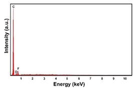
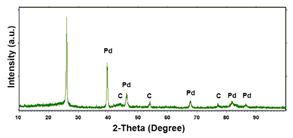
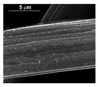
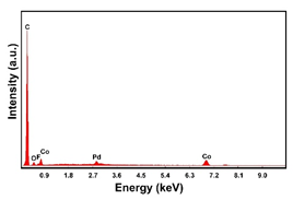
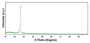
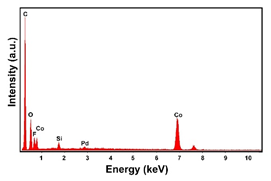
To obtain cathode materials that can be used for HER in acidic aqueous solutions, binary alloys of Pd and Co have been synthesized on CP, that was used as a porous support for the gas diffusion layer (GDL). Table 1 (line 1) shows the SEM micrograph of the CP support before deposition. It is possible to observe that CP consists of interconnected carbon fibers determining a porous three-dimensional structure on a micrometric scale. EDS analysis shows the presence of a carbon peak (C), and a fluorine peak (F), the latter due to the polytetrafluoroethylene treatment of the CP to make it hydrophobic [81,82]. In the XRD patter the presence of a very intense peak at about 2θ = 26.7° is clear visible, which is characteristic of the crystallographic plane (002) of graphite [83,84]. Additionally, two minor peaks at 2θ = 53.5° and 2θ = 18° are present. The peak at 53.5° is related to the plane (004) of graphite, while the peak at 18° could not be identified and is probably due to impurities of the CP substrate.
Initially, the deposition process for pure Pd and pure Co was studied. This study is very important for determining the optimal conditions for the co-deposition of elements, whose standard reduction potentials have different values. In particular, the standard reduction potential for Co2+/Co is equal to −0.272 V/NHE, while for Pd2+/Pd it is equal to +0.9 V/NHE. The significant difference between the two standard reduction potentials complicates the co-deposition process, unless a chelating agent that limits the Pd activity is used [85]. For this reason, the tetrammine palladium dinitrate was used because the potential of Pd ( NH 3 ) 4 2 + /Pd is equal to 0.0 V/NHE due to the high stability of the complex [86,87].
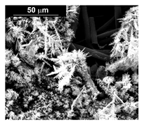
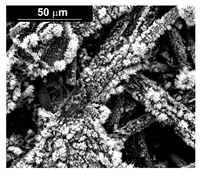
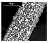
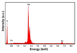
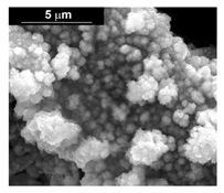
The deposits obtained in the different conditions (at a different current density and deposition time) are characterized by a different quantity of electrodeposited material and by a different morphology. In particular, we found an increase of catalyst loading both with the increase of current density and deposition time. The morphology showed that for the samples obtained at a current density of −15.6 mAcm−2, the deposit has a needle-like structure as shown in Table 1 (line 2). This structure is present both for long and short deposition times. A needle-like structure, similarly obtained in [88], ensures a large active surface area and thus good electrocatalytic performance.
As the electrodeposition time increases, only the amount of deposit changes and, consequently, the coverage of the deposition area. Similarly, the samples obtained at −1.56 mAcm−2, as shown in Table 1 (line 3) show the previously described morphology. However, operating at a lower current density allows the reduction of the height of the Pd needles compared to those formed for the same times, but at −15.6 mAcm−2. A more detailed study of all the samples carried out on the internal CP fibers shows the presence of a globular morphology. This result indicates that the porous CP structure is not electrochemically uniform as demonstrated in [89,90]. The level of penetration of the electrolyte into the porous structure and, above all, the level of densification of the fibers at some points can determine the areas of higher or lower density of local current with consequent greater development of the needle-like structure, clearly visible in the SEM images reported in Table 1 (lines 2 and 3).
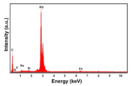
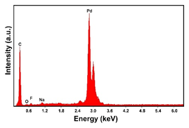
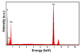
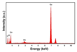
In the EDS spectra, the intensity of the Pd peak, that changes with the deposition time and with the deposition current density, indicates that the deposits are characterized by different quantities of electrodeposited material. The C and F peaks, also evident in the spectra, are both attributable to the CP substrate.
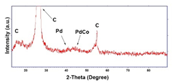
Regarding the crystallographic structure, the XRD patterns showed the presence of the diffraction peaks of the metallic Pd, which were identified by comparison with the database (card 87–637) [83,91]. In particular, the XRD peaks at 2θ = 40.0°, 46.8°, 68.1°, 82.2° and 85.5° indicate the presence of (111), (200), (220), (311) and (311) planes, respectively, and correspond to the face-centered cubic phase of Pd metal. The Pd deposit is polycrystalline with the most intense peak along the plane (111). Using the half-height width of the main peak and Scherrer’s formula [92], a grain size of about 15 ± 1 nm was calculated for the deposit obtained at −1.56 mAcm−2. This value changes very little with the deposition time, while it tends to increase slightly as the deposition current density increases, reaching a value of about 18 ± 1.3 nm in the case of the deposit obtained at −15.6 mAcm−2. The diffraction peaks of the CP substrate are also visible in the patterns. In the XRD patterns of the different samples only small differences were observed in terms of intensity of the Pd diffraction peaks, which were slightly lower in the samples obtained at the low deposition times and/or low current densities.
The electrodeposition process and the electrochemical behavior of pure Co was also investigated. The electrolytes for the electrodeposition of Co and its alloys are numerous, both acidic and alkaline, and usually include additives with various functions, from stabilizers, such as boric acid or ammonium citrate, to levelers and brighteners. The most widely used electrolytes are undoubtedly the acid solutions of sulphates, sulfamates, and, in specific cases, fluoborates and chlorides, both for the pure metal and for its alloys [86,93]. In this study, the Co electrodeposition process was carried out using a solution of cobalt sulphate 0.035 M. The electrodeposition was conducted at the same values of current density and deposition time employed for the Pd deposition. In the case of tests carried out at −15.6 mAcm−2, the Co deposit is present in all samples in increasing quantities as the deposition time increases. Instead, for the deposition carried out at −1.56 mAcm−2 it was observed that the Co deposit is present with evident quantities only in the samples obtained for times longer than 30 min.
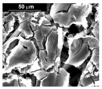
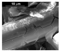
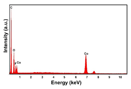
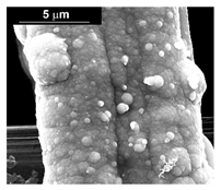
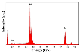
The presence of the oxygen peak in the EDS spectra, especially at low current densities, suggests the probable co-deposition of Co oxides/hydroxides [94]. These compounds can be formed to the local alkalization of the solution due to the simultaneous evolution of hydrogen during deposition [95]. From a morphological point of view, it was found that all Co samples obtained at −15.6 mAcm−2 are characterized by a clod (dry mud) morphology that almost completely covers the CP surface. In fact, only a few fibers of the support remain uncovered as shown in Table 1 (line 4). This morphology is attributable to a dehydration effect that occurs during the air drying of the samples performed after deposition. The same morphology was also found at −1.56 mAcm−2, although the amount of deposit was much lower and only covered the surface of the fibers (Table 1, line 5).
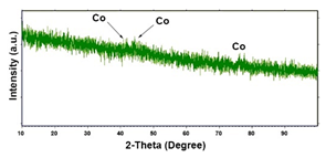
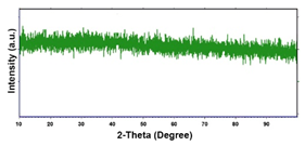
For the crystallographic structure, regardless of the deposition conditions, the XRD results showed that all Co deposits are amorphous-nanocrystalline. Even if the spectra do not show perfectly evident peaks, through a smoothing operation it is possible to highlight the presence of some low intensity peaks. For comparison with the database (card 05–0727) [91], we have seen that the peaks at 2θ of 41.8°, 44.4° and 76.6°, indicate the presence of (100), (002) and (110) planes, respectively, and are attributable to the metallic Co with the hexagonal close-packed (hcp) structure [96,97,98]. The shape of the spectrum, in which the substrate peaks do not appear completely, the very low intensity of the Co peaks leads us to conclude that the deposit has a nanocrystalline near-amorphous nature.
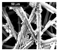
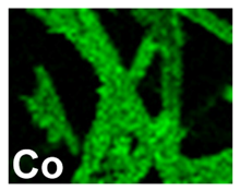
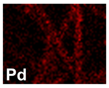
After investigating the deposition process of pure metals, the electrodeposition process of the Pd–Co alloy was studied, to identify the optimal operating conditions (composition of the solution, current density and deposition time). The morphology showed that for depositions carried out at −15.6 mAcm−2 (Table 2, line 2) and −1.56 mAcm−2 (Table 2, line 1), the Pd–Co alloys have a globular structure only for very short deposition times (60 s). This structure changes significantly for longer deposition times. In fact, for a deposition time of 300 s, the deposits have a compact morphology formed by the coalescence of the globular structure. This effect is accentuated as the deposition time increases, with the tendency to form a compact deposit that tends to cover the entire surface of the CP. The samples were further characterized by EDS mapping. A uniform distribution of Co and Pd was observed in all deposition conditions, as evident in Table 2 (line 6), where a representative EDS map of Pd and Co was reported.
From the crystallographic point of view, for a content of Pd greater than 90%, and therefore for short deposition time, in the XRD patters the diffraction peaks of Pd are present, but they are very broad. Thus, the grain size is very small, and in fact, using Scherrer’s equation [92], an average size of 3.2 ± 0.3 nm was found. At 43.6° a very broad and low intensity peak is present which is assigned to (111) plane of cobalt palladium alloy with a cubic system (card 65–6174) [91,99]. The wideness and intensity of this peak suggest a very low crystallinity of the alloy also observed by other authors [100,101]. For long deposition times, due to the formation of Co rich alloys, the deposit becomes amorphous, due to the nature of Co. This same effect was also observed in other Co alloys obtained by electrodeposition [61,102,103].
For the samples obtained at −15.6 mAcm−2 (Table 2, line 4), due to the higher rate of the process and its intrinsic characteristic to enrich in cobalt, deposits with about 30% of Pd were obtained at 180 s, unlike the tests carried out at −1.56 mAcm−2 (Table 2, line 3) in which the percentage is still 65% for the same time. The morphology of these deposits is the globular type and the globular density increases with the deposition time and the deposition current density. For longer times, a compact deposit was obtained resulting from the coalescence of the globular structure. Conversely, for shorter deposition times it was possible to distinguish isolated grains. The nature of these deposits was not detectable by X-ray diffraction because they were amorphous or too thin, and in fact we obtained a spectrum similar to that of CP, which differed only by a lower intensity of the diffraction peaks.
Deposition from concentrated solution of Pd (about 84%) has led to the formation of very rich Pd deposit, as can be observed in Table 3 where the average composition calculated from the EDS results were reported. The Pd concentration decreases with increasing deposition time, remaining, however, above 56% for alloys obtained at −15.6 mAcm−2 and more than 40% for deposits obtained at −1.56 mAcm−2. For the deposition of the Pd–Co alloy from dilute solutions (about 17% in Pd), the formation of a Pd rich deposit is observed only for short deposition times. With the increase of deposition time the cobalt content increases (Table 4). This effect is attributable to the progressive Pd impoverishment in solution.
The electrochemical characterization of the deposits was carried out by means of voltammetry tests for 100 consecutive cycles, followed by a galvanostatic test carried out at −50 mAcm−2 for 3 h to verify the stability in acid environment under HER. All tests were carried out in 2 M H2SO4 at 25 °C. The CV was performed on an electrode area of 0.07 cm2, while for the galvanostatic test the entire electrode area, about 1.33 cm2, was used. Figure 1a shows the CVs for an alloy obtained at −156 mAcm−2 and for a deposition time of 900 s. For all investigated samples, the CVs have a similar trend to that shown in Figure 1a. Apart from the first cycles, the CV curves are settling and finally overlapping. At the same voltage, different current density values are reached, which were found to be functions of the deposition time and the deposition current density. To better compare the data obtained for the different samples, the current value of the HER at −0.8 V (NHE) was calculated from the CV. The results are shown in Table 5 for pure Pd and Co deposits and in Figure 1b for alloys obtained from the dilute Pd solution, (see also Table 3 for the results of the alloys obtained from the Pd-concentrated solutions). With the same procedure the as-obtained CP (without an electrocatalyst) was tested founding a hydrogen evolution current density of about −35 mAcm−2 at −0.8 V (NHE). This value was significantly lower than the current density values recorded at the same potential for the samples with the catalyst.
In the case of the pure Pd deposits, the hydrogen evolution current density at −0.8 V (NHE) increased as the deposition current density increased (Table 5). As predictable, a higher value of the deposition current density leads to a greater amount of deposit, and therefore, a greater electrocatalytic effect. In particular, a hydrogen evolution current density of −382 mAcm−2 was measured for the sample obtained for one hour of deposition at −1.56 mAcm−2, and a value of −412 mAcm−2 for the sample deposited at −15.6 mAcm−2 with the same deposition time. A similar behavior was observed for the sample of pure Co (Table 5). In fact, for the deposits obtained at −15.6 mAcm−2 and for a deposition time of 1 h, the current for hydrogen evolution was −281 mAcm−2 compared to −80 mAcm−2 measured for the deposits obtained at −1.56 mAcm−2 and with the same deposition time. As expected, the performance of the pure Co is worse than that of the pure Pd deposits [104].
In the case of the alloys, the best results were obtained from the diluted Pd solutions (Figure 1b). In fact, for the concentrated solutions, Table 3, hydrogen evolution currents were slightly superior to pure Pd (Table 5) were measured. Consequently, these alloys were not further investigated, since there was no improvement in their performance compared to the pure Pd. This result is attributable both to the low content of Co and to the small specific area. As discussed below, a high Co content is, instead, necessary to increase the electrocatalytic performance. The morphology of these deposits, especially for long deposition times, tends to become compact and thus have a low surface area. For alloys obtained from diluted solutions, the hydrogen evolution current changes greatly with the alloy composition, Figure 1b. Except for deposits obtained at −1.56 mAcm−2, the presence of a maximum deposition time of 900 s can be observed. Thus, this result is indicative that the addition of Co to Pd improves the electrocatalytic characteristics of the alloys up to an optimum value of approximately 90% after which, for further enrichment in Co, the benefits lapse. In particular, for alloys obtained at −15.6 mAcm−2, a hydrogen evolution current of −710 mAcm−2 is obtained at the maximum. This value is higher than −412 mAcm−2 that is the best value obtained for the pure Pd.
From the electrocatalytic point of view, considering these positive results of the deposits obtained from dilute Pd solutions, the investigation has been extended to deposits obtained initially from dilute solutions, but at a higher deposition current density of −156 mAcm−2. The morphology of these samples consisted in globular shapes that were coated with a visible patina, which however, was removed if the sample was treated in 2 M H2SO4 for a few minutes leaving a deposit with clear and well-defined contours (Table 2, line 5). An interesting aspect of these alloys is that the deposition affects not only the first layer of the CP fibers, but also the underlying fibers.
The electrochemical characterization of these deposits showed excellent electrocatalytic properties as shown by CV (Figure 1a). The hydrogen evolution current (Figure 1b) at −0.8 V/NHE increased with the deposition time for deposits up to 900 s, for which a value of −760 mAcm−2 was obtained. For deposits formed at longer times (1800 s) the hydrogen evolution current was −700 mAcm−2. At −156 mAcm−2, the maximum hydrogen evolution current was obtained, which was greater than that relative to the alloy obtained at −15.6 mAcm−2 (−710 mAcm−2); also higher than the value obtained for the pure Pd (−390 mAcm−2). Considering that the alloy composition obtained at −15.6 and −156 mAcm−2 was practically identical in both cases, this different behavior could be attributed to the morphological differences of the deposit, and in particular to a higher specific surface area obtained at −156 mAcm−2.
An exhaustive explanation of the presence of a maximum in the hydrogen evolution current corresponding to an alloy composition of the order of 10% in Pd is currently not available. The absence of a direct correlation between Pd content and the maximum in the hydrogen evolution current confirms the role of other parameters such as a deposited mass and its morphology. In the first approximation, it could be considered that for the deposition times that were shorter than the maximum, small amounts of deposit were obtained even if they were very rich in Pd. At longer times, however, the amount of deposit increased, as did the concentration of Co. Therefore, the presence of a maximum would be indicative of the best compromise between the quantity of deposit and its composition. The maximum performance for a specific quantity of Co present in the alloy was also found on other Co alloys [105]. Moreover, as reported by Li et al. [48], the presence of amorphous Co has a beneficial effect on the HER performance because it accelerates the water dissociation. However, the quantity of the deposit must also be considered in relation to its morphology, that is related to the specific surface area. In fact, as the deposition time increases, the deposit tends to become more compact; therefore, it has a smaller specific surface. It can be assumed, then, that the maximum corresponds to that optimal condition of the amount of deposit, the morphology and the content of Pd and Co.
Galvanostatic tests, Figure 2, showed that the HER from a 2 M H2SO4 solution at −50 mAcm−2 ran at different voltage values depending on the type of sample. In the case of the pure deposits (Figure 2a), it was noted that the electrode polarization was lower for deposits obtained at a higher deposition current density. This result can be explained in terms of the quantity of deposit present on the electrode. In other words, as the deposition current density increases, at the same deposition time, the deposit mass is higher so the electrode performance, from an electrocatalytic point of view, improves. The other observation is that the polarization of the electrode tends to increase progressively, at a rate that is greater for deposits obtained at a lower deposition current density. This can be attributed to the fact that during the HER there may be a gradual detachment of the deposit from the support resulting in a deterioration of the performance of the electrode. Obviously, this effect is more accentuated for deposits obtained at a lower current density since, as mentioned above, in this case its initial amount of deposit is lower. This effect is, however, of little relevance because a MEA-type assembly should significantly hinder this phenomenon.
For Pd–Co alloys a similar trend (Figure 2b) was observed. In fact, in the three hours of the test, the electrode polarization tended to decrease very slowly. It is interesting to note, however, that the electrode potential of the alloys was lower than the two pure metals, indicating better electrocatalytic properties. It was observed that for the deposit formed at −156 mAcm−2 an almost stationary value of the electrode voltage of −0.12 V/NHE was measured against the value of −0.27 V/NHE of the deposit of the pure Pd. This result confirms the best electrocatalytic behavior of the deposit formed at −156 mAcm−2, attributed to a higher specific surface area of this alloy and to the synergistic interactions between Pd and Co.
In Table 6 a comparison of our results with the reported performances in the literature relative to the Pd–Co-based electrodes is reported. This Table shows that our results align with the published data.

3.2. The Array of Nanowires

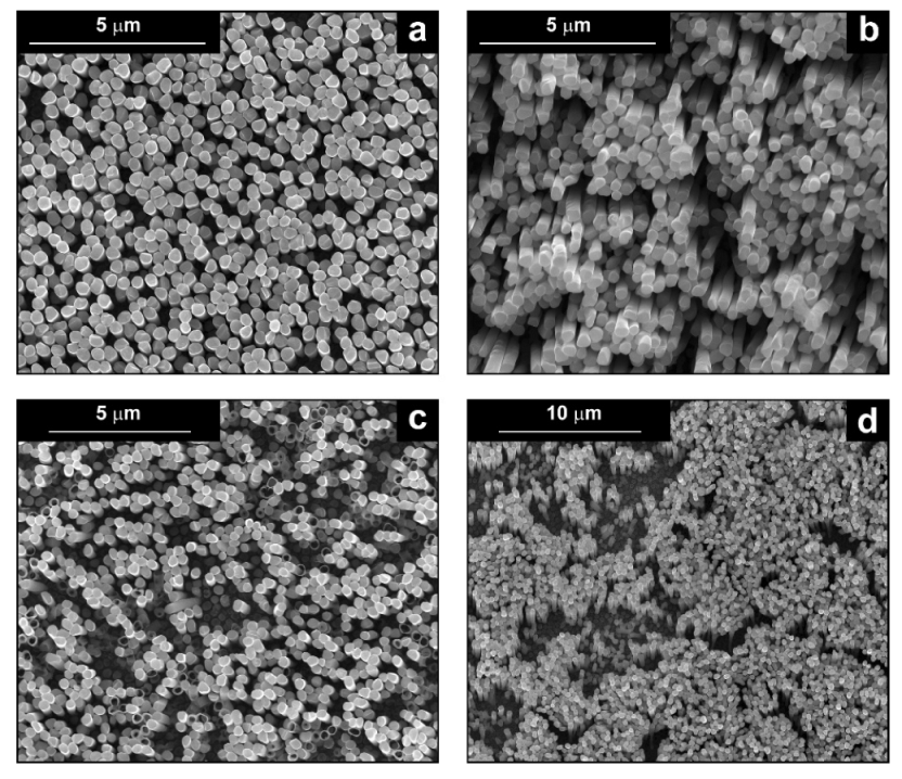
The fabrication procedure for nanowires of the Pd–Co alloy is detailed in [53]. The results showed that depending on the deposition conditions, it was possible to obtain arrays of both nanowires and nanotubes, and, as we have also shown in this work, it was possible to obtain both palladium-rich crystalline alloys and amorphous alloys rich in Co. In this study, to make a comparison with the data obtained using CP as a support for deposition, only arrays with about 8% of Pd were tested. In the case of deposits on CP, in fact, the alloys with this composition showed the best performances. According to the results discussed above, an array rich in Co is obtained when a dilute solution of palladium is used [53]. Also in this case, the alloy was found to be amorphous and the electrodes consisted of cylindrical nanowires (length around 4.5 μm), which replicated the morphology of pores of the alumina template.
Before electrochemical characterization, to obtain an array of nanowires to be exposed to the H2SO4 solution, it is necessary to dissolve the alumina template in a NaOH solution. After this phase, the nanowires’ morphology is clearly visible, as shown in Figure 3a,b, which show that nanowires are uniformly distributed on the entire surface of electrode. However, the results obtained using this type of electrode were not satisfactory. Despite the first cycle of CVs having shown a very high hydrogen evolution current (about three times higher than the best result obtained for depleted alloys on CP), a rapid decay of the performance was observed. In fact, already after the 5th CV cycle, the hydrogen evolution current was lower than the value obtained in the case of CP. Analyzing the samples using the electron microscope showed that already after the first cycle of CV (Figure 3c,d) many nanowires had detached from the surface of the electrode. This was due to the vigorous hydrogen evolution, which makes the nanowires mechanically unstable. The loss of the nanowires leads to a decrease in the active area of the electrode and consequently to a drop in its performance.
To overcome this problem, the template used for the fabrication of arrays will be changed and a polycarbonate membrane will be used instead of the alumina membrane. A polycarbonate template is characterized by a lower porosity and consequently allows the fabrication of arrays with a lower density of nanowires, which have empty interspaces. This ensures a better evolution of the hydrogen from their surface and, therefore, a better mechanical stability. This hypothesis is confirmed by the good performance obtained with nanostructured Ni-based electrodes fabricated with polycarbonate membranes, that also have a very good mechanical stability [56].

4. Conclusions

In this paper, the study of the electrochemical deposition process of Pd–Co alloys on CP support and AAM was reported. The characteristics of the alloy were investigated through changing the compositions of the deposition bath, the deposition current density and the deposition time. SEM, EDS, XRD and electrochemical tests were performed in all samples to define the chemical–physical characteristics and the electrochemical performance. For comparison, pure Pd and Co deposits were also prepared in order to compare their performance with those of alloys. The results obtained show that the composition of the alloy is strongly dependent on all the parameters that control the electrodeposition process (time, current density and bath composition). In particular, the content of Pd decreases both with the increase of deposition time and the decrease of Pd concentration in the deposition solution. The best alloy was obtained at the high investigated deposition current density (−156 mAcm−2) and for 900 s of deposition time. Under these conditions, a Pd content in the alloy is of the order of 7–10%. The electrochemical characterization showed that, with this alloy a hydrogen evolution current at −0.8 V (NHE) of −760 mAcm−2 can be reached. The galvanostatic tests, performed for 3 h in 2 M H2SO4 and at 25 °C, also showed that in the case of this alloy the electrode potential remains roughly constant for the duration of the test. This result is an index of a good electrode stability.
Unexciting results were obtained in the case of the arrays of nanowires due to the lack of optimal mechanical stability of these structures under hydrogen evolution. New tests are in progress to overcome this problem, using polycarbonate membranes as templates for the fabrication of the nanowires.

Author Contributions

Conceptualization, B.P., F.G. and R.I.; methodology, S.C., F.B. and F.P.; validation, S.C., F.B. and F.P.; formal analysis, C.Z., B.P., F.G. and R.I.; investigation, C.Z., S.C., F.B. and F.P.; data curation, C.Z., S.C., F.B. and F.P.; writing—original draft preparation, R.I.; writing—review and editing, C.Z., G.A., R.I., P.M. and R.M.; supervision, G.A., R.I., P.M. and R.M.; funding acquisition, G.A., R.I., P.M. and R.M. All authors have read and agreed to the published version of the manuscript.

Funding

This research was funded by MUR, CNMS Centro Nazionale per la Mobilità sostenibile grant number CN00000023.

Institutional Review Board Statement

Not applicable.

Informed Consent Statement

Not applicable.

Data Availability Statement

Not applicable.

Conflicts of Interest

The authors declare no conflict of interest.

References

  1. Reijnders, L. Fuels for the future. J. Integr. Environ. Sci. 2009, 6, 279–294. [Google Scholar] [CrossRef]
  2. Martins, F.; Felgueiras, C.; Smitkova, M.; Caetano, N. Analysis of Fossil Fuel Energy Consumption and Environmental Impacts in European Countries. Energies 2019, 12, 964. [Google Scholar] [CrossRef] [Green Version]
  3. Badwal, S.P.S.; Giddey, S.S.; Munnings, C.; Bhatt, A.I.; Hollenkamp, A.F. Emerging electrochemical energy conversion and storage technologies. Front. Chem. 2014, 2, 79. [Google Scholar] [CrossRef] [Green Version]
  4. Sunseri, C.; Cocchiara, C.; Ganci, F.; Moncada, A.; Oliveri, R.L.; Patella, B.; Piazza, S.; Inguanta, R. Nanostructured electrochemical devices for sensing, energy conversion and storage. Chem. Eng. Trans. 2016, 47, 43–48. [Google Scholar] [CrossRef]
  5. Kadier, A.; Kalil, M.S.; Logroño, W.; Mohamed, A.; Hasan, H.A. Hydrogen Production Through Electrolysis. In Encyclopedia of Sustainability Science and Technology; Meyers, R.A., Ed.; Springer New York: New York, NY, USA, 2018; pp. 1–20. ISBN 978-1-4939-2493-6. [Google Scholar]
  6. Mac Dowell, N.; Sunny, N.; Brandon, N.; Herzog, H.; Ku, A.Y.; Maas, W.; Ramirez, A.; Reiner, D.M.; Sant, G.N.; Shah, N. The hydrogen economy: A pragmatic path forward. Joule 2021, 5, 2524–2529. [Google Scholar] [CrossRef]
  7. Brauns, J.; Turek, T. Alkaline Water Electrolysis Powered by Renewable Energy: A Review. Processes 2020, 8, 248. [Google Scholar] [CrossRef] [Green Version]
  8. Santos, A.L.; Cebola, M.-J.; Santos, D.M.F. Towards the Hydrogen Economy—A Review of the Parameters That Influence the Efficiency of Alkaline Water Electrolyzers. Energies 2021, 14, 3193. [Google Scholar] [CrossRef]
  9. Le Bideau, D.; Mandin, P.; Benbouzid, M.; Kim, M.; Sellier, M.; Ganci, F.; Inguanta, R. Eulerian Two-Fluid Model of Alkaline Water Electrolysis for Hydrogen Production. Energies 2020, 13, 3394. [Google Scholar] [CrossRef]
  10. Shiva Kumar, S.; Himabindu, V. Hydrogen production by PEM water electrolysis—A review. Mater. Sci. Energy Technol. 2019, 2, 442–454. [Google Scholar] [CrossRef]
  11. Ahmad Kamaroddin, M.F.; Sabli, N.; Tuan Abdullah, T.A.; Siajam, S.I.; Abdullah, L.C.; Abdul Jalil, A.; Ahmad, A. Membrane-Based Electrolysis for Hydrogen Production: A Review. Membranes 2021, 11, 810. [Google Scholar] [CrossRef] [PubMed]
  12. Falcão, D.S.; Pinto, A.M.F.R. A review on PEM electrolyzer modelling: Guidelines for beginners. J. Clean. Prod. 2020, 261, 121184. [Google Scholar] [CrossRef]
  13. Campagna Zignani, S.; Faro, M.L.; Carbone, A.; Italiano, C.; Trocino, S.; Monforte, G.; Aricò, A.S. Performance and stability of a critical raw materials-free anion exchange membrane electrolysis cell. Electrochim. Acta 2022, 413, 140078. [Google Scholar] [CrossRef]
  14. Niaz, A.K.; Park, J.-Y.; Lim, H.-T. Operational parameters correlated with the long-term stability of anion exchange membrane water electrolyzers. Int. J. Hydrogen Energy 2021, 46, 31550–31562. [Google Scholar] [CrossRef]
  15. Niaz, A.K.; Akhtar, A.; Park, J.-Y.; Lim, H.-T. Effects of the operation mode on the degradation behavior of anion exchange membrane water electrolyzers. J. Power Sources 2021, 481, 229093. [Google Scholar] [CrossRef]
  16. Niaz, A.K.; Lim, H.-T. Stability Tests on Anion Exchange Membrane Water Electrolyzer under On-Off Cycling with Continuous Solution Feeding. J. Electrochem. Sci. Technol. 2022, 13, 369–376. [Google Scholar] [CrossRef]
  17. Wang, L.; Chen, M.; Küngas, R.; Lin, T.-E.; Diethelm, S.; Maréchal, F.; Van Herle, J. Power-to-fuels via solid-oxide electrolyzer: Operating window and techno-economics. Renew. Sustain. Energy Rev. 2019, 110, 174–187. [Google Scholar] [CrossRef]
  18. Kamlungsua, K.; Su, P.-C.; Chan, S.H. Hydrogen Generation Using Solid Oxide Electrolysis Cells. Fuel Cells 2020, 20, 644–649. [Google Scholar] [CrossRef]
  19. Li, Z.; Zhang, H.; Xu, H.; Xuan, J. Advancing the multiscale understanding on solid oxide electrolysis cells via modelling approaches: A review. Renew. Sustain. Energy Rev. 2021, 141, 110863. [Google Scholar] [CrossRef]
  20. Noussan, M.; Raimondi, P.P.; Scita, R.; Hafner, M. The role of green and blue hydrogen in the energy transition—A technological and geopolitical perspective. Sustainability 2021, 13, 298. [Google Scholar] [CrossRef]
  21. Osman, A.I.; Mehta, N.; Elgarahy, A.M.; Hefny, M.; Al-Hinai, A.; Al-Muhtaseb, A.H.; Rooney, D.W. Hydrogen production, storage, utilisation and environmental impacts: A review. Environ. Chem. Lett. 2022, 20, 153–188. [Google Scholar] [CrossRef]
  22. Oliveira, A.M.; Beswick, R.R.; Yan, Y. A green hydrogen economy for a renewable energy society. Curr. Opin. Chem. Eng. 2021, 33, 100701. [Google Scholar] [CrossRef]
  23. Bareiß, K.; de la Rua, C.; Möckl, M.; Hamacher, T. Life cycle assessment of hydrogen from proton exchange membrane water electrolysis in future energy systems. Appl. Energy 2019, 237, 862–872. [Google Scholar] [CrossRef]
  24. Jurasz, J.; Canales, F.A.; Kies, A.; Guezgouz, M.; Beluco, A. A review on the complementarity of renewable energy sources: Concept, metrics, application and future research directions. Sol. Energy 2020, 195, 703–724. [Google Scholar] [CrossRef]
  25. Egeland-Eriksen, T.; Hajizadeh, A.; Sartori, S. Hydrogen-based systems for integration of renewable energy in power systems: Achievements and perspectives. Int. J. Hydrogen Energy 2021, 46, 31963–31983. [Google Scholar] [CrossRef]
  26. David, M.; Ocampo-Martínez, C.; Sánchez-Peña, R. Advances in alkaline water electrolyzers: A review. J. Energy Storage 2019, 23, 392–403. [Google Scholar] [CrossRef] [Green Version]
  27. Gan, L.; Jiang, P.; Lev, B.; Zhou, X. Balancing of supply and demand of renewable energy power system: A review and bibliometric analysis. Sustain. Futures 2020, 2, 100013. [Google Scholar] [CrossRef]
  28. Hiesl, A.; Ajanovic, A.; Haas, R. On current and future economics of electricity storage. Greenh. Gases Sci. Technol. 2020, 10, 1176–1192. [Google Scholar] [CrossRef]
  29. Mitali, J.; Dhinakaran, S.; Mohamad, A.A. Energy storage systems: A review. Energy Storage Sav. 2022, 1, 166. [Google Scholar] [CrossRef]
  30. Lucas, T.R.; Ferreira, A.F.; Santos Pereira, R.B.; Alves, M. Hydrogen production from the WindFloat Atlantic offshore wind farm: A techno-economic analysis. Appl. Energy 2022, 310, 118481. [Google Scholar] [CrossRef]
  31. Calado, G.; Castro, R. Hydrogen Production from Offshore Wind Parks: Current Situation and Future Perspectives. Appl. Sci. 2021, 11, 5561. [Google Scholar] [CrossRef]
  32. Mohammadi, A.; Mehrpooya, M. A comprehensive review on coupling different types of electrolyzer to renewable energy sources. Energy 2018, 158, 632–655. [Google Scholar] [CrossRef]
  33. Yue, M.; Lambert, H.; Pahon, E.; Roche, R.; Jemei, S.; Hissel, D. Hydrogen energy systems: A critical review of technologies, applications, trends and challenges. Renew. Sustain. Energy Rev. 2021, 146, 111180. [Google Scholar] [CrossRef]
  34. Ursúa, A.; Barrios, E.L.; Pascual, J.; San Martín, I.; Sanchis, P. Integration of commercial alkaline water electrolysers with renewable energies: Limitations and improvements. Int. J. Hydrogen Energy 2016, 41, 12852–12861. [Google Scholar] [CrossRef]
  35. Ursúa, A.; San Martín, I.; Barrios, E.L.; Sanchis, P. Stand-alone operation of an alkaline water electrolyser fed by wind and photovoltaic systems. Int. J. Hydrogen Energy 2013, 38, 14952–14967. [Google Scholar] [CrossRef]
  36. Wang, S.; Lu, A.; Zhong, C.-J. Hydrogen production from water electrolysis: Role of catalysts. Nano Converg. 2021, 8, 4. [Google Scholar] [CrossRef]
  37. Sapountzi, F.M.; Gracia, J.M.; Weststrate, C.J.; Kees, J.; Fredriksson, H.O.A.; Niemantsverdriet, J.W. Electrocatalysts for the generation of hydrogen, oxygen and synthesis gas. Prog. Energy Combust. Sci. 2017, 58, 1–35. [Google Scholar] [CrossRef] [Green Version]
  38. Ferriday, T.B.; Middleton, P.H.; Kolhe, M.L. Review of the Hydrogen Evolution Reaction—A Basic Approach. Energies 2021, 14, 8535. [Google Scholar] [CrossRef]
  39. Bhalothia, D.; Krishnia, L.; Yang, S.-S.; Yan, C.; Hsiung, W.-H.; Wang, K.-W.; Chen, T.-Y. Recent Advancements and Future Prospects of Noble Metal-Based Heterogeneous Nanocatalysts for Oxygen Reduction and Hydrogen Evolution Reactions. Appl. Sci. 2020, 10, 7708. [Google Scholar] [CrossRef]
  40. Wang, Y.; Zhang, L.; Hu, C.; Yu, S.; Yang, P.; Cheng, D.; Zhao, Z.-J.; Gong, J. Fabrication of bilayer Pd-Pt nanocages with sub-nanometer thin shells for enhanced hydrogen evolution reaction. Nano Res. 2019, 12, 2268–2274. [Google Scholar] [CrossRef]
  41. Tominaka, S.; Momma, T.; Osaka, T. Electrodeposited Pd-Co catalyst for direct methanol fuel cell electrodes: Preparation and characterization. Electrochim. Acta 2008, 53, 4679–4686. [Google Scholar] [CrossRef]
  42. Xu, C.; Liu, Y.; Zhang, H.; Geng, H. A Nanoporous PdCo Alloy as a Highly Active Electrocatalyst for the Oxygen-Reduction Reaction and Formic Acid Electrooxidation. Chem. Asian J. 2013, 8, 2721–2728. [Google Scholar] [CrossRef] [PubMed]
  43. Sarkar, S.; Peter, S.C. An overview on Pd-based electrocatalysts for the hydrogen evolution reaction. Inorg. Chem. Front. 2018, 5, 2060–2080. [Google Scholar] [CrossRef]
  44. Elumalai, P.; Vasan, H.N.; Munichandraiah, N.; Shivashankar, S.A. Kinetics of hydrogen evolution on submicron size Co, Ni, Pd and Co–Ni alloy powder electrodes by d.c. polarization and a.c. impedance studies. J. Appl. Electrochem. 2002, 32, 1005–1010. [Google Scholar] [CrossRef]
  45. Martín, A.J.; Chaparro, A.M.; Daza, L. Electrochemical quartz crystal microbalance study of the electrodeposition of Co, Pt and Pt–Co alloy. J. Power Sources 2007, 169, 65–70. [Google Scholar] [CrossRef]
  46. Conway, B.E.; Jerkiewicz, G. Relation of energies and coverages of underpotential and overpotential deposited H at Pt and other metals to the ‘volcano curve’ for cathodic H2 evolution kinetics. Electrochim. Acta 2000, 45, 4075–4083. [Google Scholar] [CrossRef]
  47. Zabinski, P.; Mech, K.; Banbur-Pawlowska, S.; Kowalik, R. Modification of Electrodeposited Co-Pd Alloy Catalysts By Superimposed High Magnetic Field. ECS Meet. Abstr. 2015, MA2015-02, 907. [Google Scholar] [CrossRef]
  48. Li, L.; Ji, Y.; Luo, X.; Geng, S.; Fang, M.; Pi, Y.; Li, Y.; Huang, X.; Shao, Q. Compressive Strain in N-Doped Palladium/Amorphous-Cobalt (II) Interface Facilitates Alkaline Hydrogen Evolution. Small 2021, 17, 2103798. [Google Scholar] [CrossRef]
  49. Ganci, F.; Lombardo, S.; Sunseri, C.; Inguanta, R. Nanostructured electrodes for hydrogen production in alkaline electrolyzer. Renew. Energy 2018, 123, 117–124. [Google Scholar] [CrossRef]
  50. Battaglia, M.; Inguanta, R.; Piazza, S.; Sunseri, C. Fabrication and characterization of nanostructured Ni–IrO2 electrodes for water electrolysis. Int. J. Hydrogen Energy 2014, 39, 16797–16805. [Google Scholar] [CrossRef]
  51. Cirone, J.; Dondapati, J.S.; Chen, A. Design of bimetallic nickel-iron quantum dots with tunable compositions for enhanced electrochemical water splitting. Electrochim. Acta 2021, 392, 139016. [Google Scholar] [CrossRef]
  52. Inguanta, R.; Ferrara, G.; Piazza, S.; Sunseri, C. Fabrication and characterization of metal and metal oxide nanostructures grown by metal displacement deposition into anodic alumina membranes. Chem. Eng. Trans. 2011, 24, 199–204. [Google Scholar] [CrossRef]
  53. Patella, B.; Piazza, S.; Sunseri, C.; Inguanta, R. Anodic Alumina Membranes: From Electrochemical Growth to Use as Template for Fabrication of Nanostructured Electrodes. Appl. Sci. 2022, 12, 869. [Google Scholar] [CrossRef]
  54. Ganci, F.; Baguet, T.; Aiello, G.; Cusumano, V.; Mandin, P.; Sunseri, C.; Inguanta, R. Nanostructured Ni Based Anode and Cathode for Alkaline Water Electrolyzers. Energies 2019, 12, 3669. [Google Scholar] [CrossRef] [Green Version]
  55. Du, L.; Feng, D.; Xing, X.; Fu, Y.; Fonseca, L.F.; Yang, D. Palladium/cobalt nanowires with improved hydrogen sensing stability at ultra-low temperatures. Nanoscale 2019, 11, 21074–21080. [Google Scholar] [CrossRef]
  56. Ganci, F.; Patella, B.; Cannata, E.; Cusumano, V.; Aiello, G.; Sunseri, C.; Mandin, P.; Inguanta, R. Ni alloy nanowires as high efficiency electrode materials for alkaline electrolysers. Int. J. Hydrogen Energy 2021, 46, 35777–35789. [Google Scholar] [CrossRef]
  57. Degaga, G.D.; Kaur, S.; Pandey, R.; Jaszczak, J.A. First-Principles Study of a MoS2-PbS van der Waals Heterostructure Inspired by Naturally Occurring Merelaniite. Materials 2021, 14, 1649. [Google Scholar] [CrossRef]
  58. Ganci, F.; Buccheri, B.; Patella, B.; Cannata, E.; Aiello, G.; Mandin, P.; Inguanta, R. Electrodeposited nickel–zinc alloy nanostructured electrodes for alkaline electrolyzer. Int. J. Hydrogen Energy 2021, 47, 11302–11315. [Google Scholar] [CrossRef]
  59. Serôdio Costa, B.F.; Arias-Serrano, B.I.; Yaremchenko, A.A. Development of Ni-Sr(V,Ti)O3-δ Fuel Electrodes for Solid Oxide Fuel Cells. Materials 2021, 15, 278. [Google Scholar] [CrossRef]
  60. Buccheri, B.; Ganci, F.; Patella, B.; Aiello, G.; Mandin, P.; Inguanta, R. Ni-Fe alloy nanostructured electrodes for water splitting in alkaline electrolyser. Electrochim. Acta 2021, 388, 138588. [Google Scholar] [CrossRef]
  61. Ganci, F.; Cusumano, V.; Livreri, P.; Aiello, G.; Sunseri, C.; Inguanta, R. Nanostructured Ni–Co alloy electrodes for both hydrogen and oxygen evolution reaction in alkaline electrolyzer. Int. J. Hydrogen Energy 2021, 46, 10082–10092. [Google Scholar] [CrossRef]
  62. Ding, D.; Huang, J.; Deng, X.; Fu, K. Recent Advances and Perspectives of Nanostructured Amorphous Alloys in Electrochemical Water Electrolysis. Energy Fuels 2021, 35, 15472–15488. [Google Scholar] [CrossRef]
  63. Kumar, A.; Mohammadi, M.M.; Swihart, M.T. Synthesis, growth mechanisms, and applications of palladium-based nanowires and other one-dimensional nanostructures. Nanoscale 2019, 11, 19058–19085. [Google Scholar] [CrossRef] [PubMed]
  64. Kelaidis, N.; Zervos, M.; Lathiotakis, N.N.; Chroneos, A.; Tanasă, E.; Vasile, E. Vapor–liquid–solid growth and properties of one dimensional PbO and PbO/SnO2 nanowires. Mater. Adv. 2022, 3, 1695–1702. [Google Scholar] [CrossRef]
  65. Oliveri, R.L.; Insinga, M.G.; Pisana, S.; Patella, B.; Aiello, G.; Inguanta, R. High-Performance Lead-Acid Batteries Enabled by Pb and PbO2 Nanostructured Electrodes: Effect of Operating Temperature. Appl. Sci. 2021, 11, 6357. [Google Scholar] [CrossRef]
  66. Insinga, M.G.; Oliveri, R.L.; Sunseri, C.; Inguanta, R. Template electrodeposition and characterization of nanostructured Pb as a negative electrode for lead-acid battery. J. Power Sources 2019, 413, 107–116. [Google Scholar] [CrossRef]
  67. Inguanta, R.; Piazza, S.; Sunseri, C.; Cino, A.; Di Dio, V.; La Cascia, D.; Miceli, R.; Rando, C.; Zizzo, G. An electrochemical route towards the fabrication of nanostructured semiconductor solar cells. In Proceedings of the SPEEDAM 2010, Pisa, Italy, 14–16 June 2010; pp. 1166–1171. [Google Scholar] [CrossRef]
  68. Patella, B.; Inguanta, R.; Piazza, S.; Sunseri, C. Nanowire ordered arrays for electrochemical sensing of H2O2. Chem. Eng. Trans. 2016, 47, 19–24. [Google Scholar] [CrossRef]
  69. O’Sullivan, B.; O’Sullivan, S.; Narayan, T.; Shao, H.; Patella, B.; Seymour, I.; Inguanta, R.; O’Riordan, A. A Direct Comparison of 2D versus 3D Diffusion Analysis at Nanowire Electrodes: A Finite Element Analysis and Experimental Study. Electrochim. Acta 2022, 408, 139890. [Google Scholar] [CrossRef]
  70. Patella, B.; Piazza, S.; Sunseri, C.; Inguanta, R. NiO thin film for mercury detection in water by square wave anodic stripping voltammetry. Chem. Eng. Trans. 2017, 60, 1–6. [Google Scholar] [CrossRef]
  71. Verma, S.; Khosla, A.; Arya, S. Performance of Electrochemically Synthesized Nickel-Zinc and Nickel-Iron (Ni–Zn//Ni–Fe) Nanowires as Battery Type Supercapacitor. J. Electrochem. Soc. 2020, 167, 120527. [Google Scholar] [CrossRef]
  72. Verma, S.; Gupta, V.; Khosla, A.; Kumar, S.; Arya, S. High performance asymmetric supercapacitor based on vertical nanowire arrays of a novel Ni@Co–Fe LDH core@shell as negative and Ni(OH)2 as positive electrode. Nanotechnology 2020, 31, 245401. [Google Scholar] [CrossRef]
  73. Yang, P.; Ding, Y.; Lin, Z.; Chen, Z.; Li, Y.; Qiang, P.; Ebrahimi, M.; Mai, W.; Wong, C.P.; Wang, Z.L. Low-Cost High-Performance Solid-State Asymmetric Supercapacitors Based on MnO2 Nanowires and Fe2O3 Nanotubes. Nano Lett. 2014, 14, 731–736. [Google Scholar] [CrossRef] [PubMed]
  74. Oliveri, R.L.; Patella, B.; Di Pisa, F.; Mangione, A.; Aiello, G.; Inguanta, R. Fabrication of CZTSe/CIGS Nanowire Arrays by One-Step Electrodeposition for Solar-Cell Application. Materials 2021, 14, 2778. [Google Scholar] [CrossRef] [PubMed]
  75. Pal, B.; Sarkar, K.J.; Banerji, P. Fabrication and studies on Si/InP core-shell nanowire based solar cell using etched Si nanowire arrays. Sol. Energy Mater. Sol. Cells 2020, 204, 110217. [Google Scholar] [CrossRef]
  76. Yue, G.; Lin, Y.; Wen, X.; Wang, L.; Peng, D. SnS homojunction nanowire-based solar cells. J. Mater. Chem. 2012, 22, 16437. [Google Scholar] [CrossRef]
  77. Bertero, E.; Manzano, C.V.; Bürki, G.; Philippe, L. Stainless steel-like FeCrNi nanostructures via electrodeposition into AAO templates using a mixed-solvent Cr(III)-based electrolyte. Mater. Des. 2020, 190, 108559. [Google Scholar] [CrossRef]
  78. Pendergast, A.D.; Glasscott, M.W.; Renault, C.; Dick, J.E. One-step electrodeposition of ligand-free PdPt alloy nanoparticles from water droplets: Controlling size, coverage, and elemental stoichiometry. Electrochem. Commun. 2019, 98, 1–5. [Google Scholar] [CrossRef]
  79. Inguanta, R.; Rinaldo, E.; Piazza, S.; Sunseri, C. Lead Nanowires for Microaccumulators Obtained Through Indirect Electrochemical Template Deposition. Electrochem. Solid-State Lett. 2010, 13, K1–K4. [Google Scholar] [CrossRef] [Green Version]
  80. Inguanta, R.; Ferrara, G.; Livreri, P.; Piazza, S.; Sunseri, C. Ruthenium Oxide Nanotubes Via Template Electrosynthesis. Curr. Nanosci. 2011, 7, 210–218. [Google Scholar] [CrossRef]
  81. Zhang, R.; Yang, B.; Shao, Z.; Yang, D.; Ming, P.; Li, B.; Zhang, C. Mechanism and Model for Optimizing Polytetrafluoroethylene Distribution to Improve the Electrical and Thermal Conductivity of Treated Carbon Fiber Paper in Fuel Cells. ACS Appl. Mater. Interfaces 2021, 13, 14207–14220. [Google Scholar] [CrossRef]
  82. Yu, S.; Hao, J.; Li, J.; Zhang, L. Effect of distribution of polytetrafluoroethylene on durability of gas diffusion backing in proton exchange membrane fuel cell. Mater. Res. Bull. 2020, 122, 110684. [Google Scholar] [CrossRef]
  83. Lafuente, B.; Downs, R.T.; Yang, H.; Stone, N. 1. The power of databases: The RRUFF project. In Highlights in Mineralogical Crystallography; Armbruster, T., Danisi, R.M., Eds.; DE GRUYTER: Berlin, Germany, 2015; pp. 1–30. ISBN 978-3-11-041704-3. [Google Scholar]
  84. Ungár, T.; Gubicza, J.; Ribárik, G.; Pantea, C.; Zerda, T.W. Microstructure of carbon blacks determined by X-ray diffraction profile analysis. Carbon 2002, 40, 929–937. [Google Scholar] [CrossRef] [Green Version]
  85. Brenner, A. Electrodeposition of Alloys Principles and Practice; Elsevier Science: Saint Louis, MO, USA, 2014; ISBN 978-1-4832-2311-7. [Google Scholar]
  86. Schlesinger, M.; Paunovic, M. (Eds.) Modern Electroplating, 5th ed.; The Electrochemical Society Series; Wiley: Hoboken, NJ, USA, 2010; ISBN 978-0-470-16778-6. [Google Scholar]
  87. Tominaka, S.; Osaka, T. Nanoporous PdCo Catalyst for Microfuel Cells: Electrodeposition and Dealloying. Adv. Phys. Chem. 2011, 2011, 821916. [Google Scholar] [CrossRef]
  88. Zhou, R.; Zhou, W.; Zhang, H.; Du, Y.; Yang, P.; Wang, C.; Xu, J. Facile template-free synthesis of pine needle-like Pd micro/nano-leaves and their associated electro-catalytic activities toward oxidation of formic acid. Nanoscale Res. Lett. 2011, 6, 381. [Google Scholar] [CrossRef] [PubMed] [Green Version]
  89. Mohammadzadeh Kakhki, R. A review to recent developments in modification of carbon fiber electrodes. Arab. J. Chem. 2019, 12, 1783–1794. [Google Scholar] [CrossRef] [Green Version]
  90. Liu, C.; Sun, C.; Gao, Y.; Lan, W.; Chen, S. Improving the Electrochemical Properties of Carbon Paper as Cathodes for Microfluidic Fuel Cells by the Electrochemical Activation in Different Solutions. ACS Omega 2021, 6, 19153–19161. [Google Scholar] [CrossRef] [PubMed]
  91. International Centre for Diffraction Data. Power Diffraction File; International Centre for Diffraction Data: Newtown Square, PA, USA, 2007. [Google Scholar]
  92. West, A.R. Solid State Chemistry and Its Applications; Wiley: Chichester, UK, 1984; ISBN 978-0-471-90377-2. [Google Scholar]
  93. Schiavi, P.G.; Altimari, P.; Pagnanelli, F.; Moscardini, E.; Toro, L. Synthesis of cobalt nanoparticles by electrodeposition onto aluminium foils. Chem. Eng. Trans. 2015, 43, 673–678. [Google Scholar] [CrossRef]
  94. Jiang, S.P.; Tseung, A.C.C. Reactive Deposition of Cobalt Electrodes: II. Role of Bubbling Oxygen. J. Electrochem. Soc. 1990, 137, 3381–3386. [Google Scholar] [CrossRef]
  95. Rahimi, S.A.; Norouzi, P.; Ganjali, M.R. One-step cathodic electrodeposition of a cobalt hydroxide–graphene nanocomposite and its use as a high performance supercapacitor electrode material. RSC Adv. 2018, 8, 26818–26827. [Google Scholar] [CrossRef] [Green Version]
  96. Kan, S.; Sachan, M.; Kirchhoff, J.; Majetich, S.A. Crystallographic alignment of nanoparticles during self-assembly. IEEE Trans. Magn. 2005, 41, 3370–3372. [Google Scholar] [CrossRef]
  97. Zhong, M.; Huang, J.; Yuan, J.; Rong, S.; Ou, P.; Chen, X.; Zhang, B.; Ke, Q.; Zhu, Z. Solvothermal synthesis and characterization of porous co microspheres. Mater. Tehnol. 2021, 55, 663–666. [Google Scholar] [CrossRef]
  98. Tong, G.; Yuan, J.; Wu, W.; Hu, Q.; Qian, H.; Li, L.; Shen, J. Flower-like Co superstructures: Morphology and phase evolution mechanism and novel microwave electromagnetic characteristics. CrystEngComm 2012, 14, 2071. [Google Scholar] [CrossRef]
  99. Zhong, M.; Li, L.; Zhao, K.; He, F.; Su, B.; Wang, D. PdCo alloys@N-doped porous carbon supported on reduced graphene oxide as a highly efficient electrocatalyst for hydrogen evolution reaction. J. Mater. Sci. 2021, 56, 14222–14233. [Google Scholar] [CrossRef]
  100. Yun, M.; Ahmed, M.S.; Jeon, S. Thiolated graphene oxide-supported palladium cobalt alloyed nanoparticles as high performance electrocatalyst for oxygen reduction reaction. J. Power Sources 2015, 293, 380–387. [Google Scholar] [CrossRef]
  101. Kaushik, P.; Kaur, G.; Ram Chaudhary, G.; Batra, U. Cleaner way for overall water splitting reaction by using palladium and cobalt based nanocomposites prepared from mixed metallosurfactants. Appl. Surf. Sci. 2021, 556, 149769. [Google Scholar] [CrossRef]
  102. Bera, P.; Seenivasan, H.; Rajam, K.S.; William Grips, V.K. Characterization of amorphous Co–P alloy coatings electrodeposited with pulse current using gluconate bath. Appl. Surf. Sci. 2012, 258, 9544–9553. [Google Scholar] [CrossRef]
  103. Orue, I.; García-Arribas, A.; Fdez-Gubieda, M.L.; Herreros, J.; Plazaola, F.; Barandiarán, J.M. Observation of a Strong Short Range Order in Co Rich Amorphous Alloys Prepared by Different Methods. J. Phys. IV France 1997, 7, C2-995–C2-996. [Google Scholar] [CrossRef] [Green Version]
  104. Luo, Z.; Song, K.; Li, G.; Yang, L. Hydrogen Evolution Ability of Selected Pure Metals and Galvanic Corrosion Behavior between the Metals and Magnesium. J. Electrochem. Sci. Technol. 2020, 11, 323–329. [Google Scholar] [CrossRef]
  105. Patel, P.P.; Hanumantha, P.J.; Datta, M.K.; Velikokhatnyi, O.I.; Hong, D.; Poston, J.A.; Manivannan, A.; Kumta, P.N. Cobalt based nanostructured alloys: Versatile high performance robust hydrogen evolution reaction electro-catalysts for electrolytic and photo-electrochemical water splitting. Int. J. Hydrogen Energy 2017, 42, 17049–17062. [Google Scholar] [CrossRef]
  106. Chen, J.; Xia, G.; Jiang, P.; Yang, Y.; Li, R.; Shi, R.; Su, J.; Chen, Q. Active and Durable Hydrogen Evolution Reaction Catalyst Derived from Pd-Doped Metal–Organic Frameworks. ACS Appl. Mater. Interfaces 2016, 8, 13378–13383. [Google Scholar] [CrossRef]
  107. Li, T.; Wang, R.; Yang, M.; Zhao, S.; Li, Z.; Miao, J.; Gao, Z.-D.; Gao, Y.; Song, Y.-Y. Tuning the surface segregation composition of a PdCo alloy by the atmosphere for increasing electrocatalytic activity. Sustain. Energy Fuels 2020, 4, 380–386. [Google Scholar] [CrossRef]
Figure 1. (a) The CV curves of the Pd–Co alloy obtained from dilute solution at −156 mA cm−2 for 900 s. (b) Current density values for HER (mAcm−2) at −0.8 V/NHE obtained from CV for the Pd–Co alloys obtained from a dilute solution (about 17% in Pd) at different deposition current density.
Materials 16 00474 g001
Figure 2. The galvanostatic test conducted at −50 mAcm−2 for 3 h in 2 M H2SO4 aqueous solution at 25 °C. (a) Pure Pd and Co deposits at different deposition current density for 3600 s. (b) Pd–Co alloys obtained from a dilute solution (about 17% in Pd) at different deposition current densities for 900 s.
Materials 16 00474 g002
Figure 3. FESEM images of the Pd–Co alloy: (a,b) as prepared (a) top view, ((b) tilted top view), (c,d) after CV in 2 M H2SO4 (c) top view, ((d) tilted top view).
Materials 16 00474 g003
Table 1. The FESEM, EDS and XRD of the CP and Pd and Co deposits; the electrodeposition conditions and the composition of the electrodeposition bath is also reported.
SampleFESEMEDSXRD
Carbon PaperMaterials 16 00474 i001Materials 16 00474 i002Materials 16 00474 i003
Pd
(−15.6 mA cm−2, 3600 s)
Materials 16 00474 i004Materials 16 00474 i005Materials 16 00474 i006
Pd
(−1.56 mA cm−2, 3600 s)
Materials 16 00474 i007Materials 16 00474 i008
Co
(−15.6 mA cm−2, 3600 s)
Materials 16 00474 i009Materials 16 00474 i010Materials 16 00474 i011
Co
(−1.56 mA cm−2, 3600 s)
Materials 16 00474 i012Materials 16 00474 i013
Table 2. The FESEM, EDS and XRD of CP and Pd and Co co-deposits; the electrodeposition conditions and the composition of electrodeposition bath is also reported.
SampleFESEMEDSXRD
Pd–Co
(−1.56 mA cm−2
0.035 M Pd2+, 0.0069 M Co2+, 60 s)
Materials 16 00474 i014Materials 16 00474 i015
Pd–Co
(−15.6 mA cm−2
0.035 M Pd2+, 0.0069 M Co2+, 300 s)
Materials 16 00474 i016Materials 16 00474 i017Materials 16 00474 i018
Pd–Co
(−1.56 mA cm−2
0.035 M Pd2+, 0.17 M Co2+, 60 s)
Materials 16 00474 i019Materials 16 00474 i020Materials 16 00474 i021
Pd–Co
(−15.6 mA cm−2
0.035 M Pd2+, 0.17 M Co2+, 60 s)
Materials 16 00474 i022Materials 16 00474 i023
Pd–Co
(−156 mA cm−2
0.035 M Pd2+, 0.17 M Co2+, 300 s)
Materials 16 00474 i024Materials 16 00474 i025Materials 16 00474 i026
Pd–Co
(−156 mA cm−2
0.035 M Pd2+, 0.17 M Co2+, 300 s)
Materials 16 00474 i027Materials 16 00474 i028Materials 16 00474 i029
Table 3. The composition of Pd–Co alloys obtained from concentrate solution (about 84% in Pd) and current density values for HER (mAcm−2) at −0.8 V/NHE obtained from CV carried out in 2 M H2SO4.
Deposition Time, sPd–Co−1.56 mAcm−2Pd–Co−15.6 mA cm−2
Pd%i−0.8V(NHE)
mAcm−2
Pd%i−0.8V(NHE)
mAcm−2
180040.6 ± 1.4−242 ± 856.1 ± 1.2−238 ± 10
90065.8 ± 1.1−233 ± 1056.6 ± 1.6−220 ± 12
18075.7 ± 1.2−391 ± 991.1 ± 1.4−261 ± 7
60 80.6 ± 1.6−415 ± 1396.5 ± 1.2−372 ± 8
Table 4. The composition of the Pd–Co alloy (Pd%) obtained from dilute solution (about 17% in Pd) at different deposition and current density.
Deposition Time, s−1.56 mAcm−2−15.6 mAcm−2−156 mAcm−2
180016.9 ± 1.28.4 ± 1.15.1 ± 1.1
90027.1 ± 1.19.8 ± 1.27.5 ± 1.2
18065.2 ± 1.230.2 ± 1.247.9 ± 1.4
60 72.1 ± 1.145.5 ± 1.382.2 ± 1.2
Table 5. The current density values for HER (mAcm−2) at −0.8 V/NHE obtained from CV carried out in 2 M H2SO4 for samples of Pd and Co electrodeposited on carbon paper under different conditions.
Deposition Time, sPdCo
−1.56 mAcm−2−15.6 mAcm−2−1.56 mAcm−2−15.6 mAcm−2
3600−382 ± 12−412 ± 15−80 ± 6−281 ± 9
1800−288 ± 11−313 ± 12−65 ± 4−80 ± 6
900−264 ± 10−295 ± 10−56 ± 4−71 ± 4
60 −199 ± 6−265 ± 9−43 ± 4−62 ± 6
Table 6. A comparison with the literature data.
SampleTest ConditionsPotential for HERReference
Pd–Co@CN0.5 M H2SO4
−36 mAcm−2
−0.1 V/NHE[106]
Pd–Co alloy on carbon cloth0.5 M H2SO4
−60 mAcm−2
−0.075 V/NHE[107]
Pd–Co@N–C/rGO0.5 M H2SO4
−10 mAcm−2
−0.158 V/NHE[99]
Pd–Co on Carbon Paper2 M H2SO4
−50 mAcm−2
−0.12 V/NHEThis Work
Disclaimer/Publisher’s Note: The statements, opinions and data contained in all publications are solely those of the individual author(s) and contributor(s) and not of MDPI and/or the editor(s). MDPI and/or the editor(s) disclaim responsibility for any injury to people or property resulting from any ideas, methods, instructions or products referred to in the content.