

Characteristics of the Side Surfaces and Edges of Welded Wire Meshes Used in the Construction of Welded Slotted Screens


Abstract
:1. Introduction
- The ability to withstand heavy loads;
- A high open surface area coefficient;
- Low susceptibility to clogging;
- Even and smooth surfaces of the working wires;
- High precision in manufacturing;
- High efficiency and accuracy in separation and dewatering processes.
2. Material Used for Research and Research Methodology
3. Research Results
4. Discussion of Research Results
5. Conclusions
Author Contributions
Funding
Institutional Review Board Statement
Informed Consent Statement
Data Availability Statement
Conflicts of Interest
References
- Gornyakov, V.; Sun, Y.; Ding, J.; Williams, S. Computationally efficient models of high pressure rolling for wire arc additively manufactured components. Appl. Sci. 2021, 11, 402. [Google Scholar] [CrossRef]
- Blindheim, J.; Welo, T.; Steinert, M. First demonstration of a new additive manufacturing process based on metal extrusion and solid-state bonding. Int. J. Adv. Manuf. Technol. 2019, 105, 2523–2530. [Google Scholar] [CrossRef]
- Zhang, Y.; Wu, L.; Guo, X.; Kane, S.; Deng, Y.; Jung, Y.-G.; Lee, J.-H.; Zhang, J. Additive Manufacturing of Metallic Materials: A Review. J. Mater. Eng. Perform. 2018, 27, 1–13. [Google Scholar] [CrossRef]
- Jardin, R.T.; Tuninetti, V.; Tchuindjang, J.T.; Hashemi, N.; Carrus, R.; Mertens, A.; Duchêne, L.; Tran, H.S.; Habraken, A.M. Sensitivity Analysis in the Modelling of a High Speed Steel Thin-Wall Produced by Directed Energy Deposition. Metals 2020, 10, 1554. [Google Scholar] [CrossRef]
- Deng, F.; Deng, Z.; Liang, H.; Wang, L.; Hu, H.; Xu, Y. Life prediction of slotted screen based on back-propagation neural network. Eng. Fail. Anal. 2021, 119, 104909. [Google Scholar] [CrossRef]
- Rojas-Ulloa, C.; Tuninetti, V.; Sepúlveda, H.; Betaieb, E.; Pincheira, G.; Gilles, G.; Duchêne, L.; Habraken, A.M. Accurate numerical prediction of ductile fracture and micromechanical damage evolution for Ti6Al4V alloy. Comput. Mech. 2023. [Google Scholar] [CrossRef]
- Jardin, R.T.; Tuninetti, V.; Tchuindjang, J.T.; Duchêne, L.; Hashemi, N.; Tran, H.S.; Carrus, R.; Mertens, A.; Habraken, A.M. Optimizing laser power of directed energy deposition process for homogeneous AISI M4 steel microstructure. Opt. Laser Technol. 2023, 163, 109426. [Google Scholar] [CrossRef]
- Jalouli, Z.; Caillaud, A.; Artozoul, J.; Ammar, A.; El-Abidi, A.; Fettah, A. Modelling of shrinkage formation in casting by the phase field method. Int. J. Mater. Form. 2021, 14, 885–899. [Google Scholar] [CrossRef]
- Hu, Q.; Wang, X.; Shen, X.; Tan, Z. Microstructure and Corrosion Resistance in Bimetal Materials of Q345 and 308 Steel Wire-Arc Additive Manufacturing. Crystals 2021, 11, 1401. [Google Scholar] [CrossRef]
- Rojas-Ulloa, C.; Bouffioux, C.; Jaramillo, A.F.; García-Herrera, C.M.; Hussain, T.; Duchêne, L.; Riu, G.; Roa, J.J.; Flores, P.; Habraken, A.M.; et al. Nanomechanical Characterization of the Deformation Response of Orthotropic Ti–6Al–4V. Adv. Eng. Mater. 2021, 23, 2001341. [Google Scholar] [CrossRef]
- Borowski, T. Enhancing the Corrosion Resistance of Austenitic Steel Using Active Screen Plasma Nitriding and Nitrocarburising. Materials 2021, 14, 3320. [Google Scholar] [CrossRef] [PubMed]
- Salas, A.; Berrio, M.E.; Martel, S.; Díaz-Gómez, A.; Palacio, D.A.; Tuninetti, V.; Medina, C.; Meléndrez, M.F. Towards recycling of waste carbon fiber: Strength, morphology and structural features of recovered carbon fibers. Waste Manag. 2023, 165, 59–69. [Google Scholar] [CrossRef] [PubMed]
- Cui, Y.; Zhang, G.; Cui, T.; Zhu, P.; Du, J.; Liu, N.; Chen, H. Study on magnetic abrasive finishing process of AlSi10Mg alloy curved surface formed by selective laser melting. Int. J. Adv. Manuf. Technol. 2022, 118, 3315–3330. [Google Scholar] [CrossRef]
- Poguluri, S.K.; Cho, I.H. Liquid sloshing in a rectangular tank with vertical slotted porous screen: Based on analytical, numerical, and experimental approach. Ocean. Eng. 2019, 189, 106373. [Google Scholar] [CrossRef]
- Ballo, F.; Carboni, M.; Mastinu, G.; Previati, G. Wires for spring construction: Full scale fatigue experimental tests. Meccanica 2022, 57, 213–228. [Google Scholar] [CrossRef]
- Kim, N.; Ko, D.; Kang, N.; Oh, I.Y.; VanTyne, C.J.; Moon, Y.H. Feasibility of using continuously cast round bloom as a substitute to cast ingot in the manufacture of heavy forgings. Steel Res. Int. 2020, 91, 2000079. [Google Scholar] [CrossRef]
- Deng, F.; Yin, B.; Xiao, Y.; Li, G.; Yan, C. Research on Erosion Wear of Slotted Screen Based on High Production Gas Field. Processes 2022, 10, 1640. [Google Scholar] [CrossRef]
- Pasiowiec, P.; Bańczyk, K.; Wajs, J.; Gawlista, S.; Tora, B.; Burek, A. Comparative analysis of dewatering efficiency and distribution of materials in centrifugal dewatering sieve with steel and polyurethane insert. In Proceedings of the 19th Conference on Environment and Mineral Processing, VŠB—TU The Proceedings of the 19th Conference on Environment and Mineral Processing, VŠB—TU, Ostrava, Czech Republic, 4–6 June 2015; 2015. [Google Scholar]
- Pasiowiec, P.; Bańczyk, k.; Tora, B.; Brożyna, J.; Wajs, J. The universal application of welded screens in the processes of coal, oil, natural gas, and uranium mining and processing. In Proceedings of the Materials of the XXXI Conference from the series ‘Energy Resources and Energy Issues in the National Economy’, Zakopane, Poland, 15–18 October 2017. [Google Scholar]
- Muszka, K.; Kwiecień, M.; Perzyński, K.; Majta, J.; Madej, L. Metal forming driven surface engineering of thin profile wires for high precision industrial filtration screens. Mater. Sci. CIRP Ann. 2022, 71, 265–268. [Google Scholar] [CrossRef]
- Kwiecień, M.; Rumiński, M.; Kopyściański, M.; Majta, J.; Muszka, K. The role of metal forming processes in eliminating surface defects in precision profile wires caused by superficial imperfections in the initial wire rods. In Proceedings of the Meform, Freiberg, Germany, 17–18 March 2022; pp. 41–43. [Google Scholar]
- Zhang, S.X.; Zhu, J.F.; Zhao, H.Y. Study on the Wear Behavior of Slotted Screen Plates Used for Pulp Screening. Wear 2003, 254, 1094–1100. [Google Scholar]
- Zhao, H.Y.; Shi, X.J. On the Wear Behavior of Slotted Screen Plates for Pulp Screening. Wear 2004, 256, 57–64. [Google Scholar]
- Pilarczyk, J.W.; Dyja, H.; Golis, B.; Tabuda, E. Effect of roller die drawing on structure, texture and other properties of high carbon steel wires. Met. Mater. 1998, 4, 727–731. [Google Scholar] [CrossRef]
- Kuboki, T.; Kajikawa, S. A rotary reduction of fine wires/tubes of a wide range of diameters using a pair of concave rolls. Ann. CIRP 2016, 65, 277–280. [Google Scholar] [CrossRef]
- Haddi, A.; Imad, A.; Vega, G. Analysis of temperature and speed effects on the drawing stress for improving the wire drawing process. Mater. Des. 2011, 32, 4310–4315. [Google Scholar] [CrossRef]
- Alexandrov, S.; Hwang, Y.-M.; Tsui, H.S.R. Determining the Drawing Force in a Wire Drawing Process Considering an Arbitrary Hardening Law. Processes 2022, 10, 1336. [Google Scholar] [CrossRef]
- Shukur, J.J.; Khudhir, W.S. Mohanad Qusay Abbood: Analysis of Tool Geometry and Lubrication Conditions Effect on the Forming Load During Wire Drawing Process. Adv. Sci. Technol. Res. J. 2022, 16, 279–286. [Google Scholar] [CrossRef]
- Araki, J.; Suzuki, H. Studies on wire drawing through Turks head rolls. Engineering 1975, 24, 81–114. [Google Scholar]
- Bezek, K.; Nipic, D.; Torkar, K.G.; Oder, M.; Drazic, G.; Abram, A.; Zibert, J.; Raspor, P.; Bohinc, K. Biofouling of stainless steel surfaces by four common pathogens: The effects of glucose concentration, temperature and surface roughness. Biofouling 2019, 35, 273–283. [Google Scholar] [CrossRef] [PubMed]
- Söderberg, R.; Wärmefjord, K.; Lindkvist, L.; Berlin, R. The influence of spot weld position variation on geometrical quality. Ann. CIRP 2012, 61, 13–16. [Google Scholar] [CrossRef]
- Volk, W.; Groche, P.; Brosius, A.; Ghiotti, A.; Kinsey, B.L.; Liewald, M.; Madej, L.; Min, J.; Yanagimoto, J. Models and modelling for process limits in metal forming. Ann. CIRP 2019, 68, 775–798. [Google Scholar] [CrossRef]
- Utsunomiya, H.; Takagishi, S.; Ito, A.; Matsumoto, R. Lubrication using porous surface layer for cold drawing of steel wire. Ann. CIRP 2013, 62, 235–238. [Google Scholar] [CrossRef]
- Silva, R.; Kugelmeier, C.L.; Vacchia, G.S.; Martins Junior, C.B.; Dainezi, I.; Afonso, C.R.M.; Mendes Filho, A.A.; Rovere, C.A.D. A comprehensive study of the pitting corrosion mechanism of lean duplex stainless steel grade 2404 aged at 475 °C. Corros. Sci. 2021, 191, 109738. [Google Scholar] [CrossRef]


| Profile | Steel Grade | Chemical Composition, % | ||||||||
|---|---|---|---|---|---|---|---|---|---|---|
| C | Si | Mn | S | P | Cr | Ni | Mo | N | ||
| 34Sbb | 1.4482 | 0.028 | 0.55 | 4.135 | 0.011 | 0.017 | 20.21 | 1.80 | 0.436 | - |
| 42Sbb | 1.4482 | 0.019 | 0.65 | 4.115 | 0.001 | 0.026 | 20.15 | 1.79 | 0.449 | - |
| 34Sb | 1.4016 | 0.020 | 0.43 | 0.4 | 0.011 | 0.037 | 16.04 | 0.50 | - | 0.035 |
| Q55 | 1.4016 | 0.028 | 0.40 | 0.53 | 0.014 | 0.029 | 16.16 | 0.46 | - | 0.030 |
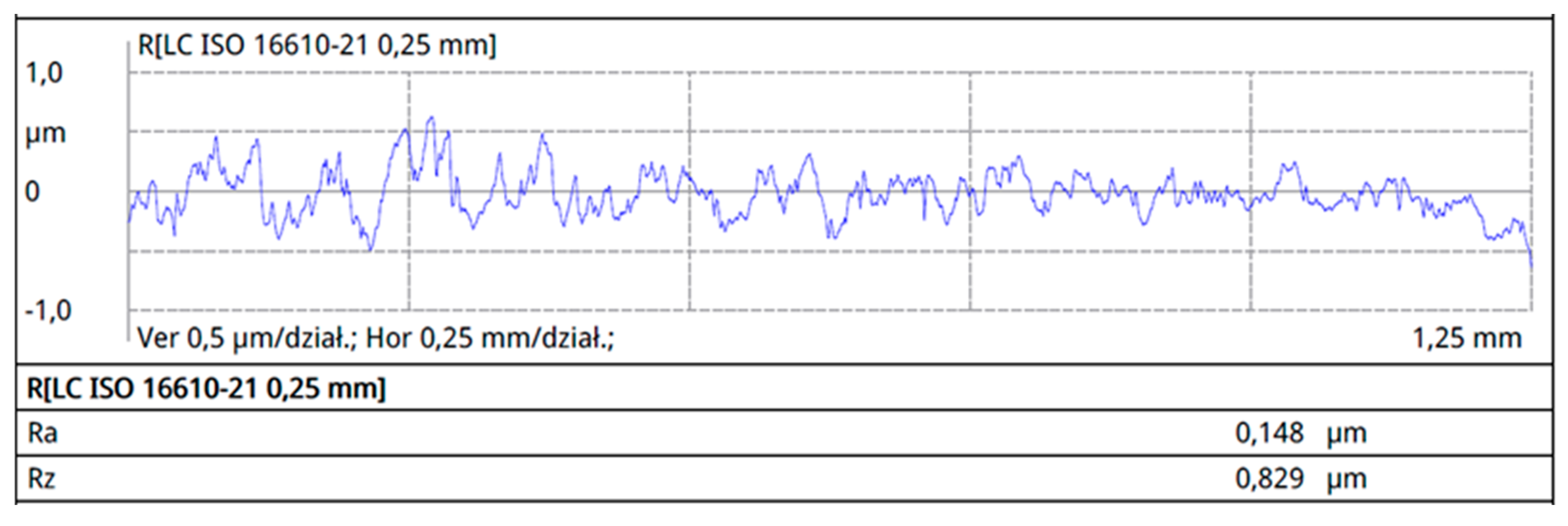
| Working Wire 34Sbb | Perpendicular to the Rolling Direction | |
|---|---|---|
| Ra [μm] | Rz [μm] | |
| mean value | 0.171 | 0.899 |
| standard deviation | 0.087 | 0.464 |
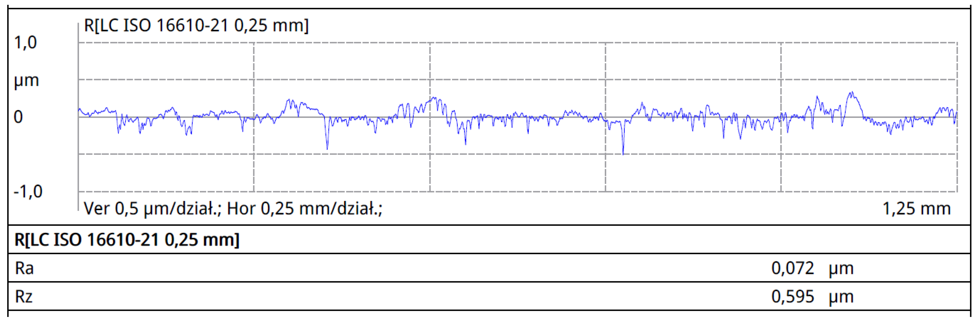
| Working wire 42Sbb | perpendicular to the rolling direction | |
| Ra [μm] | Rz [μm] | |
| mean value | 0.074 | 0.599 |
| standard deviation | 0.037 | 0.300 |
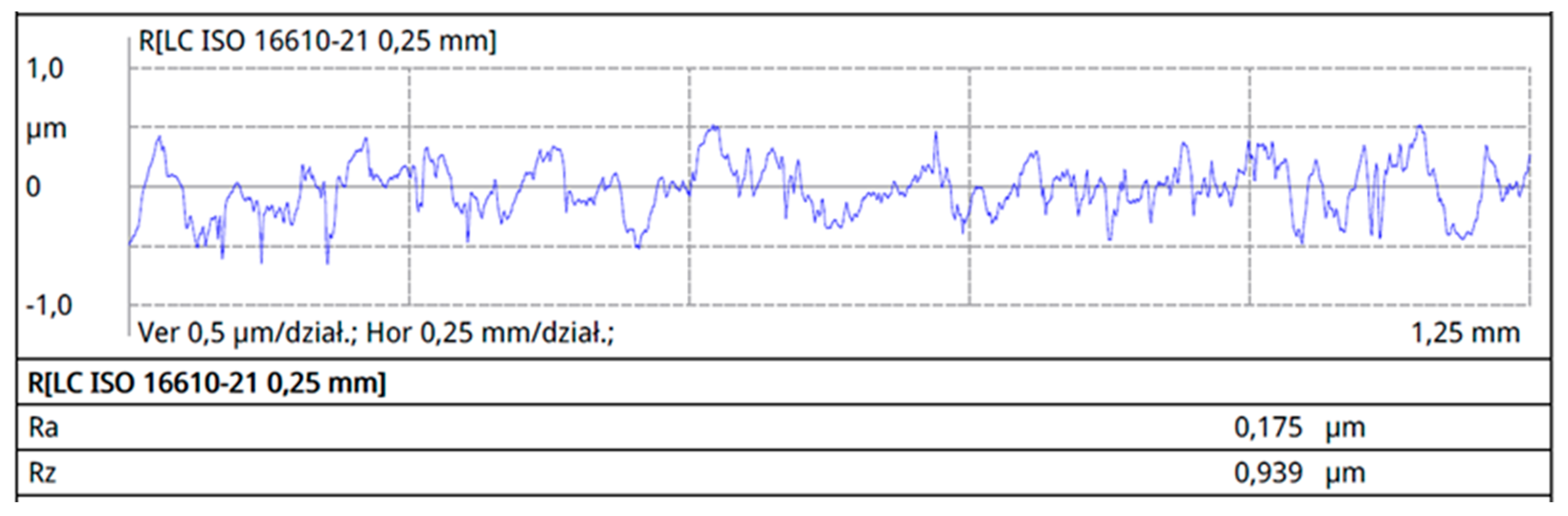
| Supporting wire 34Sb | perpendicular to the rolling direction | |
| Ra [μm] | Rz [μm] | |
| mean value | 0.218 | 1.308 |
| standard deviation | 0.113 | 0.714 |
| Supporting wire Q55 | perpendicular to the rolling direction | |
| Ra [μm] | Rz [μm] | |
| mean value | 0.502 | 2.833 |
| standard deviation | 0.258 | 1.465 |
| Working Wire 34Sbb | Perpendicular to the Rolling Direction | Lengthwise to the Rolling Direction | ||
|---|---|---|---|---|
| Ra [μm] | Rz [μm] | Ra [μm] | Rz [μm] | |
| mean value | 0.118 | 0.291 | 0.024 | 0.072 |
| standard deviation | 0.085 | 0.148 | 0.014 | 0.033 |
| Working wire 42Sbb | perpendicular to the rolling direction | lengthwise to the rolling direction | ||
| Ra [μm] | Rz [μm] | Ra [μm] | Rz [μm] | |
| mean value | 0.068 | 0.122 | 0.019 | 0.041 |
| standard deviation | 0.011 | 0.034 | 0.007 | 0.017 |
| Supporting wires 34Sb | perpendicular to the rolling direction | lengthwise to the rolling direction | ||
| Ra [μm] | Rz [μm] | Ra [μm] | Rz [μm] | |
| mean value | 0.269 | 0.705 | 0.181 | 0.499 |
| standard deviation | 0.066 | 0.139 | 0.082 | 0.210 |
| Supporting wire Q55 | perpendicular to the rolling direction | lengthwise to the rolling direction | ||
| Ra [μm] | Rz [μm] | Ra [μm] | Rz [μm] | |
| mean value | 0.114 | 0.165 | 0.073 | 0.199 |
| standard deviation | 0.065 | 0.083 | 0.070 | 0.268 |
Disclaimer/Publisher’s Note: The statements, opinions and data contained in all publications are solely those of the individual author(s) and contributor(s) and not of MDPI and/or the editor(s). MDPI and/or the editor(s) disclaim responsibility for any injury to people or property resulting from any ideas, methods, instructions or products referred to in the content. |
© 2023 by the authors. Licensee MDPI, Basel, Switzerland. This article is an open access article distributed under the terms and conditions of the Creative Commons Attribution (CC BY) license (https://creativecommons.org/licenses/by/4.0/).
Share and Cite
Bąk, M.; Wencel, S.; Wieczorek, P. Characteristics of the Side Surfaces and Edges of Welded Wire Meshes Used in the Construction of Welded Slotted Screens. Materials 2023, 16, 6701. https://doi.org/10.3390/ma16206701
Bąk M, Wencel S, Wieczorek P. Characteristics of the Side Surfaces and Edges of Welded Wire Meshes Used in the Construction of Welded Slotted Screens. Materials. 2023; 16(20):6701. https://doi.org/10.3390/ma16206701
Chicago/Turabian StyleBąk, Mariusz, Sylwia Wencel, and Paweł Wieczorek. 2023. "Characteristics of the Side Surfaces and Edges of Welded Wire Meshes Used in the Construction of Welded Slotted Screens" Materials 16, no. 20: 6701. https://doi.org/10.3390/ma16206701
APA StyleBąk, M., Wencel, S., & Wieczorek, P. (2023). Characteristics of the Side Surfaces and Edges of Welded Wire Meshes Used in the Construction of Welded Slotted Screens. Materials, 16(20), 6701. https://doi.org/10.3390/ma16206701