Article

Influence of Pulsed Arc Parameters on the Tig Welding Process for the Stainless Steel Duplex UNS S31803

by
Vinicius Marques Alves Generoso
1,
Lucas Menezes de Souza
1,
Elaine Cristina Pereira
1,
Sergio N. Monteiro
2 and
Afonso R. G. de Azevedo
3,*
1
UENF—State University of the Northern Rio de Janeiro, LAMAV—Advanced Materials Laboratory, Av. Alberto Lamego, 2000, Campos dos Goytacazes 28013-602, RJ, Brazil
2
IME—Military Institute of Engineering, Materials Science Program, Praça General Tibúrcio, 80, Urca, Rio de Janeiro 22290-270, RJ, Brazil
3
UENF—State University of the Northern Rio de Janeiro, LECIV—Civil Engineering Laboratory, Av. Alberto Lamego, 2000, Campos dos Goytacazes 28013-602, RJ, Brazil
*
Author to whom correspondence should be addressed.
Materials 2023, 16(21), 6870; https://doi.org/10.3390/ma16216870
Submission received: 29 September 2023 / Revised: 17 October 2023 / Accepted: 20 October 2023 / Published: 26 October 2023

Abstract

:
The influence of parameters involved in the pulsed electric arc, used as an energy source in the tungsten inert gas (TIG)-mediated welding of Duplex UNS S31803 stainless steel, to attend the manufacture of flexible pipes for the extraction of oil and gas is presented. A fundamental part in the manufacturing process of flexible pipelines is the welding of these strips so that corresponding TIG welds will be subjected to the same process and work conditions. Therefore, it is necessary to maintain the same properties in the welded regions. Covering the effects of each parameter of the pulsed electric arc such as peak and base current as welds, cyclic ratio, and pulsation frequency is a desirable endeavor. The final objective is the mitigation of problems that have a great impact on production, such as weld breakage during the conformation of the strip in the process and test failures. With this, tensile, bending, and ferrite percentage tests were performed on 12 samples that qualified as satisfactory in the visual aspect. A minimum tensile strength of 734.57 MPa and a maximum of 775.77 MPa were obtained where all values found are above the tensile strength limit of the base material of 620 MPa. With the completion of the study, it is possible to understand not only the response of the process to each parameter but also the tendency when changing them. Moreover, it is possible to explore the possibility of guiding the changes to achieve results about the visual aspect and the mechanical properties of the welded material.

1. Introduction

Oil and gas extraction from deep ocean waters is demanding increasingly unique technologies and materials. As an important resource which has been widely used for the transport of fluids and instrumenting systems on offshore platforms, flexible pipelines are complex structures with multiple layers whose number and type depend on the specific design requirements [1,2].
These pipelines use helical reinforcement of steel wires and strips combined with concentric layers of polymers, textile tapes, and adhesive tapes, culminating in a structure capable of withstanding considerable structural loads as well as internal and external pressures. The target of the present study, the inner layer of the flexible pipeline, which has contact with the corrosive fluid composed of oil and saline water, must be made of corrosion-resistant steel. Therefore, in its manufacture, metallic strips of stainless steel of different classes are used including the UNS S31803 steel depending on the severity of the fluid to be transported. In the specific case of oil, it will depend on the type of productive well, particularly corrosive aspects of the oil withdrawn from this well [1,2].
The manufacturing processes for these pipelines are established in forming and welding sequences. Several layers make up the flexible pipeline structure. The initial structure, made up of duplex stainless steel, mostly flexible pipelines, is fitted with a pre-formed “tape” fitting system to allow this coupling and assembly as a “spiral”. For the “profiling” process to maintain its continuity, strips of the steel in question are welded together, maintaining a continuous system until the desired length of the pipeline is obtained. Depending on the severity of the forming process, the joints must have good mechanical characteristics. This conformation consists of the “S” shape of the duplex stainless steel “tapes”, for a sequential fit and “profiling”, thus achieving what is known as a flexible pipeline. Due to the complexity of the structures produced, some regions of the generated joint may be potential sites of structural problems. This becomes more serious the greater the complexity of the alloy to be welded [1,2,3].
In addition to all requests during the manufacturing process of these pipelines, in field conditions they are subject to several constraints, among which it is worth mentioning the tensile loading of the entire assembly. In addition, compression loads can be experienced during installation in deep water, namely a buffer effect due to high hydrostatic pressure, or, in extreme situations, such as when the floating unit operates in low top angle conditions and is subject to sudden movements [1,4]. This whole complex loading system leads to a greater concern about the quality of the materials and process in use. For each pipe manufactured, several welds are performed and such unions are normally carried out through the tungsten inert gas (TIG) welding process, which has the electric arc as an energy source. TIG might be configured to provide the input of heat needed to promote the fusion of the tape with different nuances [5,6,7,8,9].
UNS S31803 duplex stainless steel is an alloy based on the Fe–Cr–Ni system. Its chemical composition and thermomechanical processing give it a biphasic microstructure with approximately equal proportions of ferrite and austenite. It typically has relevant Cr and Ni values, with very low carbon contents (less than 0.03%) and with additions of nitrogen and Mo [9,10,11,12]. Table 1 shows the percentage by weight of the alloying elements of the reference material which are the same for the sample material.
UNS S31803 duplex stainless steel has numerous advantages over traditional austenitic and ferritic stainless steels. Its mechanical strength is approximately twice that of common austenitic stainless steels, combined with good toughness. It has high resistance to stress corrosion cracking and localized corrosion in environments containing chlorides [13]. Its weldability is superior to that of ferritic stainless steel. The hardness of the base material is dependent on the type and level of cold work [14,15,16,17].
Regarding the fraction of austenite and ferrite, it is verified, according to the current literature, that the adjustment of the ferrite/austenite balance during the manufacture of these steels is established at temperatures in the order of 1000 °C [18] and that such balance is situated at around 50%. The literature shows that the welding thermal cycle has a great influence on this balance, verifying that the greater the heat flux in the cooling process, the greater the ferrite content, thus causing a greater imbalance between the phases [6,10,12].
The application of duplex stainless steels in the petrochemical sector has led to the elaboration of quality criteria for this type of steel and for welded joints, both in terms of macro and microstructure, mechanical properties, and corrosion resistance, with special attention to the fraction of ferrite/austenite. The definition of these criteria requires proper control of the transformation processes involving such materials, especially welding processes, due to the heat cycles that such processes affect the metal during the execution of welds [5,19,20].
The TIG process uses an electric arc maintained between a non-consumable W electrode and the piece to be welded as a heat source. The welding region is protected by an inert gas flow. Welding can be performed with or without filler metal and can be manual or automatic. Currently, the TIG process is most used in the welding of Al, Mg, and Ti alloys and stainless steels. The solder produced is of very good quality [6,7].
The TIG welds are autogenous, without added material, and were performed through a semi-automatic process where the movement of the torch was automated, providing repeatability and standardization. A pulsed direct current was used, which is characterized by an intensity variation in a minimum value (base current) and a maximum value (peak current). The type of wave used is the square wave, as shown in Figure 1, where the values of intensity and the duration of peak and base currents and pulse frequency must be established [6,8,21].
In order to systematize the elaboration of the settings, it is necessary to characterize the influences of the settings relevant to the electric arc pulse produced by the welding machine generator. This is an objective that technically made the proposed research project feasible.
The main advantage of pulsed current is that it allows a combination of power, good penetration, and pulse fusion while keeping the weld area relatively cool. Thus, it is possible to obtain greater penetrations than in constant direct current and to work with materials that are more sensitive to heat input with minimization of distortions of the base metal (BM). Rectangular wave pulsed current is characterized by the periodic alternation between high and low levels of welding current at a given frequency. This wave configuration allows the arc energy to be used more efficiently, bringing benefits such as greater control over the dimensional characteristics of the weld bead, greater tolerance to variations in heat dissipation, less heat input, a reduction in residual voltages and distortions in the parts as welds, greater control over the weld pool, grain refinement in the fusion zone (FZ), and a reduction in the width of the thermally affected zone (HAZ) [22,23].
This article presents a study developed to evaluate the influence of the parameters of the pulsed electric arc used as an energy source in the TIG process applied to the welding of Duplex UNS S31803 stainless steel (DSS). In total, 27 different weld settings were proposed and the visual appearance and mechanical and metallurgical properties were evaluated.

2. Materials and Methods

The DSS strip went through the hot lamination processes with subsequent treatment followed by air cooling, until reaching the final thickness of the plate. After cutting, plates have a width of 108 mm and a thickness of 2.7 mm. The chemical composition in percent by weight of the DSS strip UNS S31803 is presented in Table 1 and the mechanical properties in Table 2 [14,24]. Figure 2 shows a schematic of the experimental stages of this research.
For the execution of the welds, the semi-automatic TIG welding machine with a torch with automated displacement, Oerlikon CITOTIG II 300 DC, was used.
Therefore, 27 adjustments were proposed and elaborated through a combinatorial analysis where the alteration of each variable implied the maintenance of the others. According to Tables 3 and 5 welds were performed for each one of these adjustments.
Of the 5 welds of each adjustment that were carried out, 2 were intended for the tensile test with measurement of the percentage elongation, 2 were subjected to the bending test, and 1 was used for the metallographic test to carry out the count of the percentage of ferrite and austenite in the HAZ and in the ZF, as indicated in Figure 3c. The percentage of ferrite was determined using the color contrast method where a contrast is applied to the lightest phase, which is austenite, thus showing the percentage value of that phase in the image.
As the arc configuration depends on the peak base current values, the time of each, and the pulsation frequency, the adjustments proposed in Table 3 were determined through the following procedures:
-
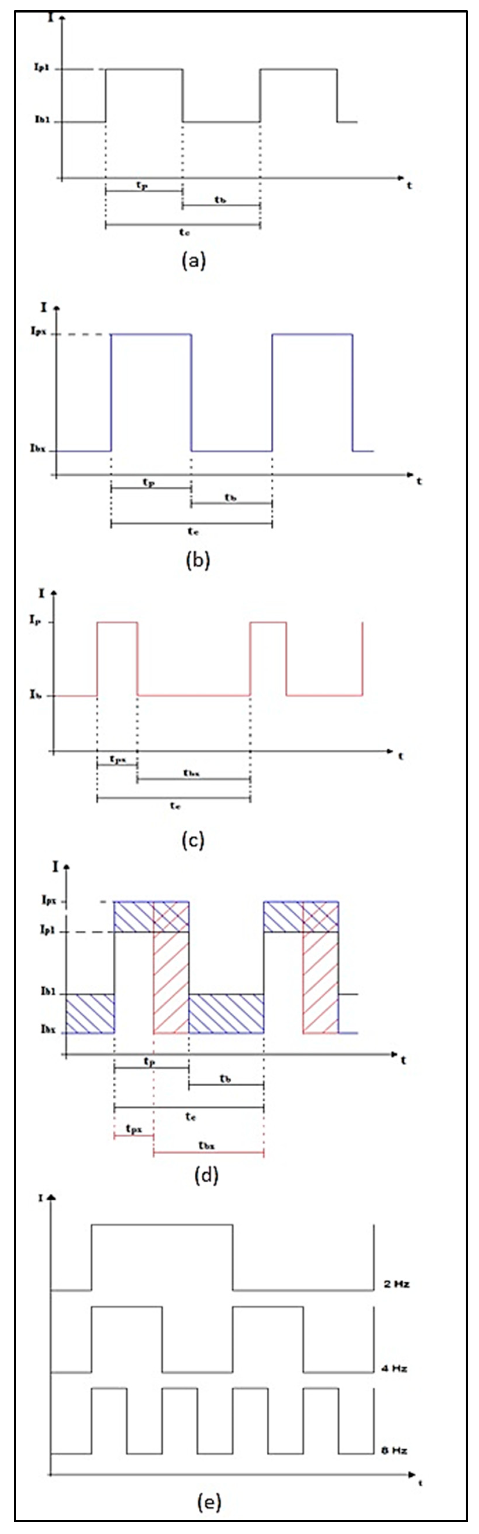
For analysis of the base and peak current values (Delta I):
The base and peak current values were relativized so that their arithmetic mean remained in all settings; however, the difference between them would be changed;
-
For baseline and peak current time analysis (RC—Cyclic Ratio):
The time values were also relativized so that the value of this ratio is the percentage ratio of peak current time over base current time;
-
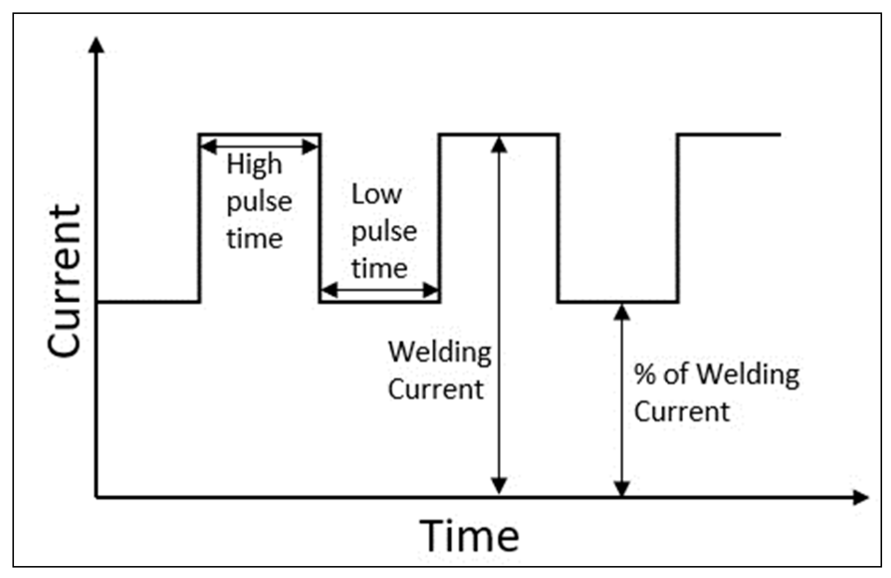
For pulsation analysis (Frequency):
The value of the pulsation frequency in an exponential scale was changed to bring greater effectiveness in the analyses.
Figure 4a illustrates the formatting of the pulsed arc while Figure 4b,c illustrates the maximum changes made and Figure 4d,e illustrates the formatting of these changes.
where:
  • Ip—Peak current or high current;
  • Ib—Base current or low current;
  • tc—Pulse time (period);
  • tp—Peak current time;
  • tb—Base current time.

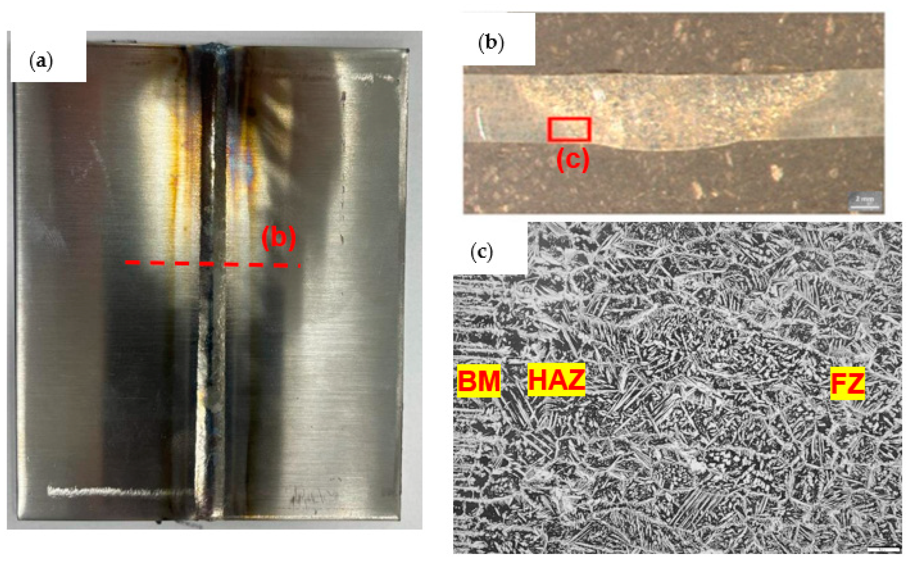
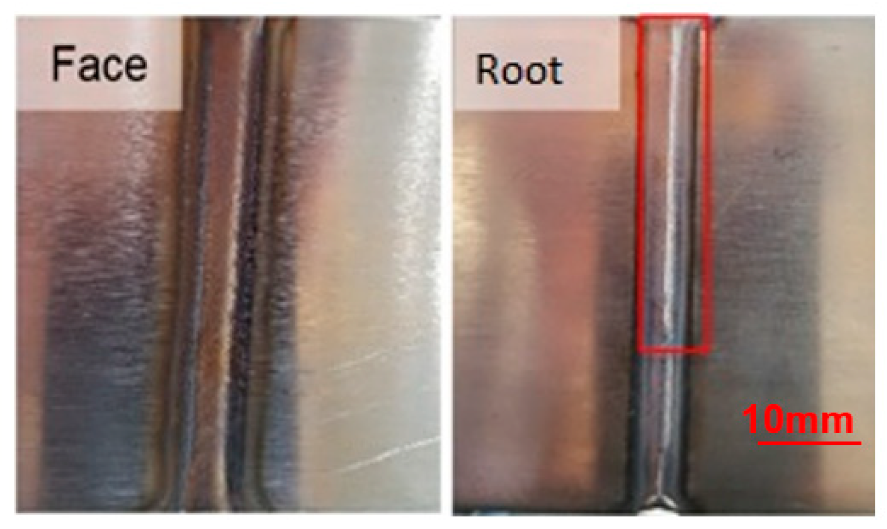
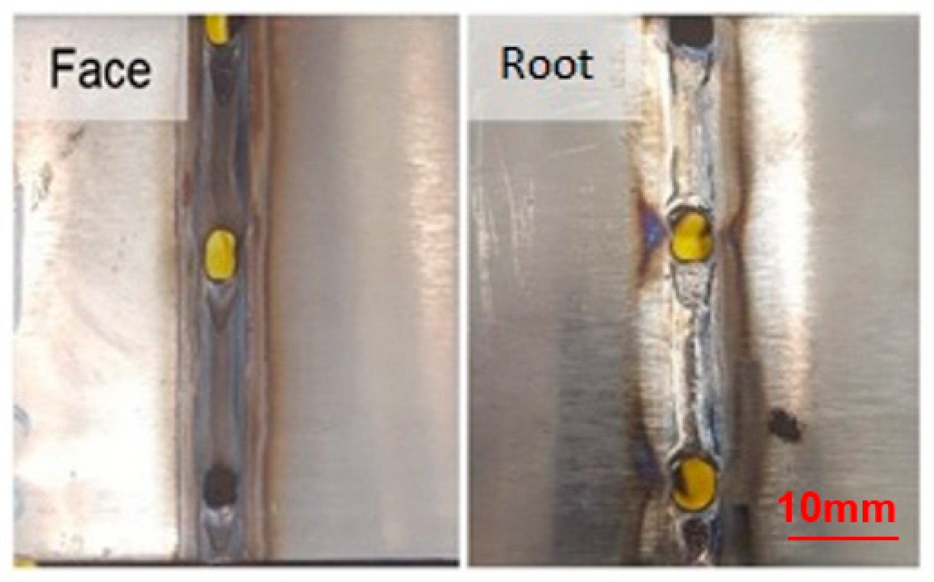
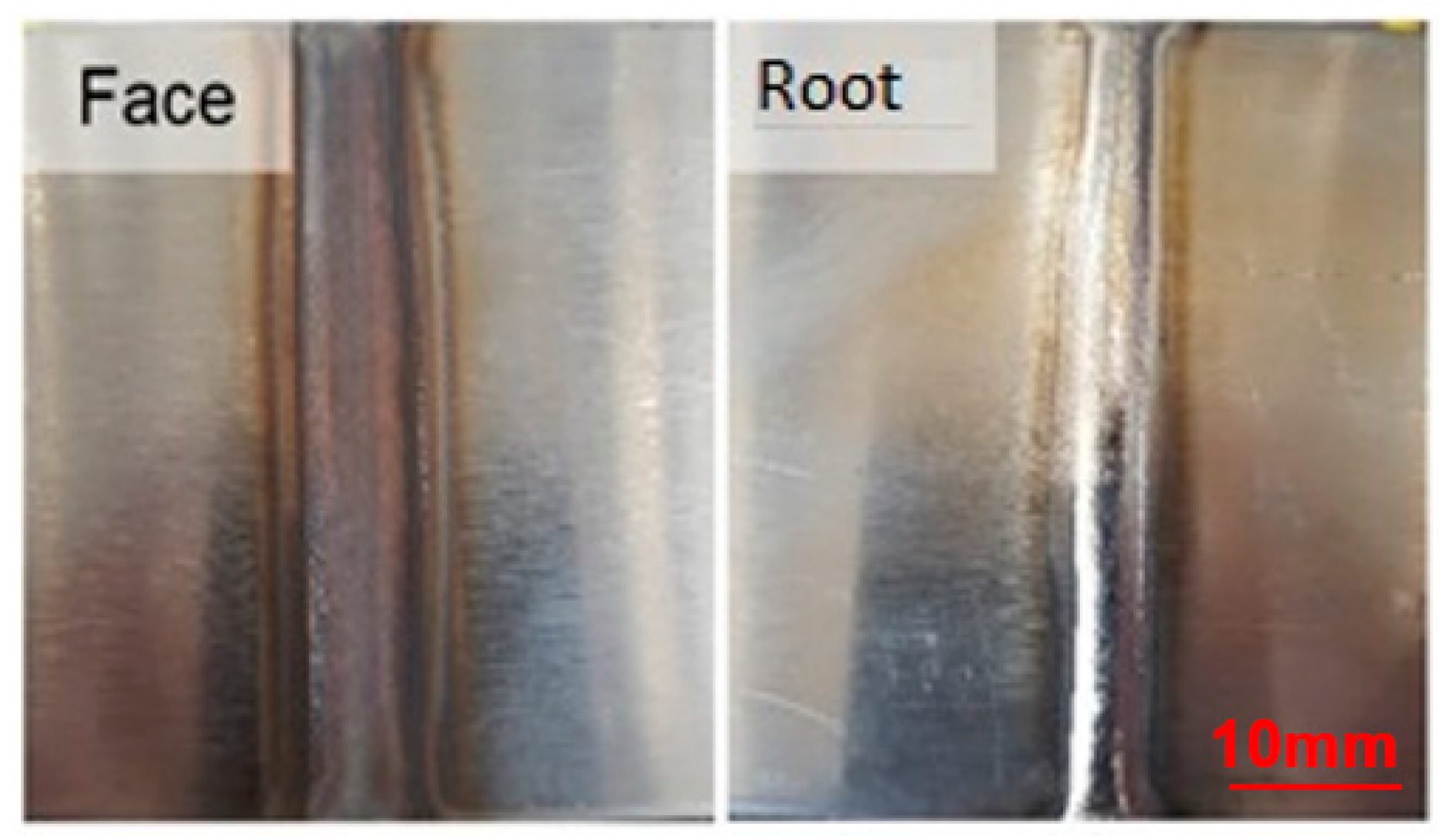
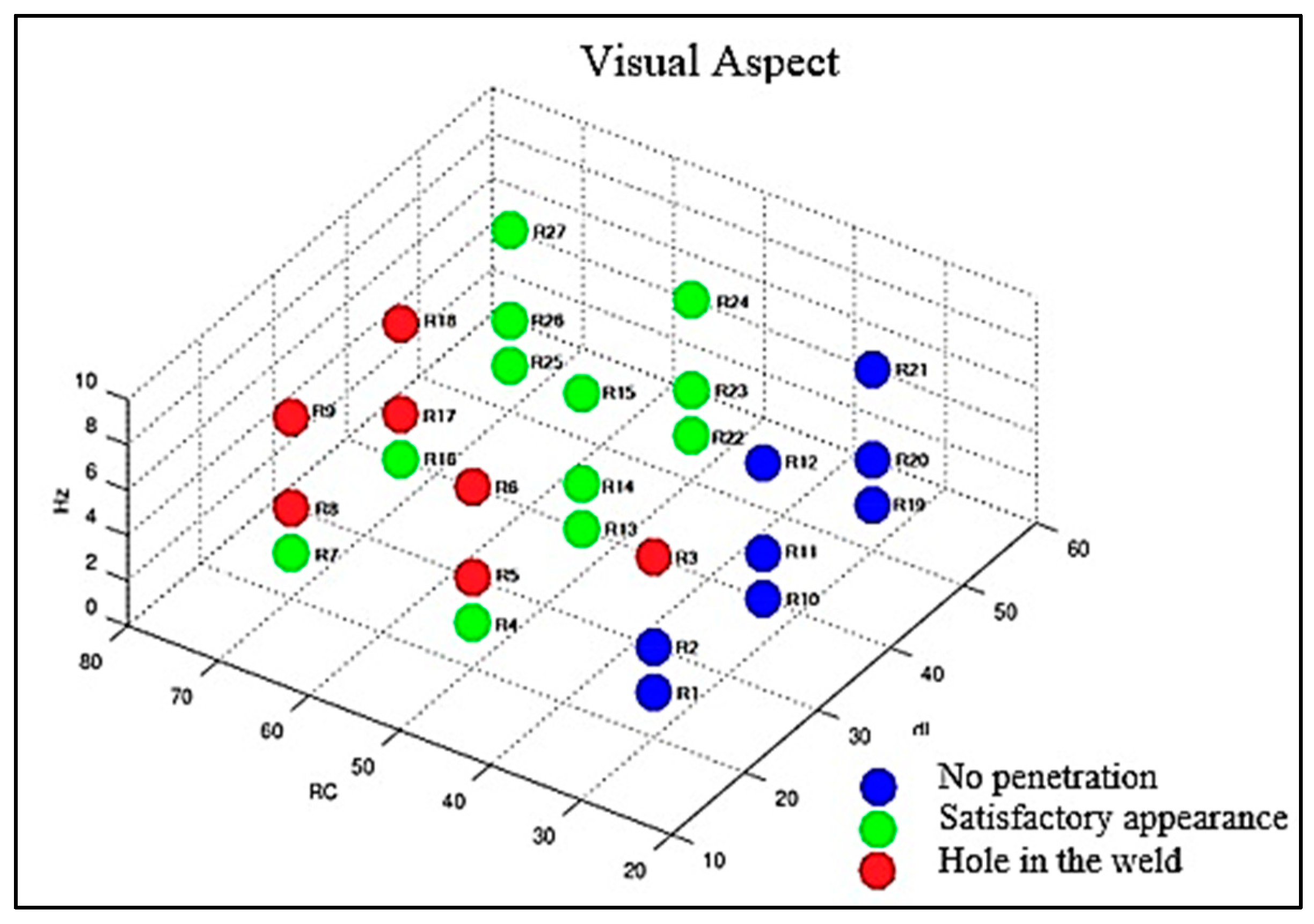
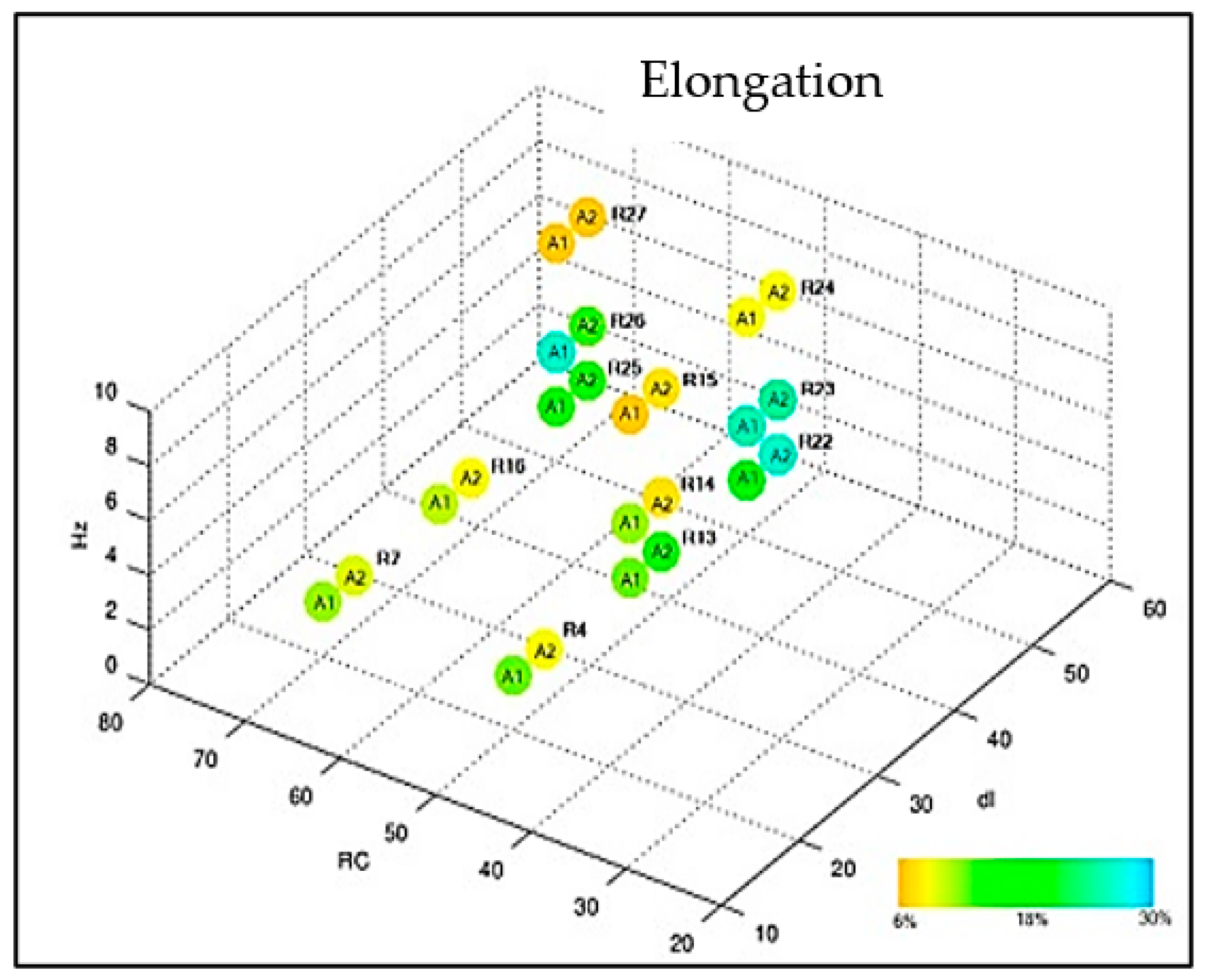
3. Results and Discussion

The results are grouped and can be seen in Table 4.
The first criterion considered for the proposed analyses was the visual aspect, determined in Figure 5, Figure 6 and Figure 7, with its results compiled in the graph of Figure 8 so that one could optimize the evaluation process. The welds from the adjustments that did not reach a satisfactory visual appearance were discarded. To this end, the continuity of the weld bead was observed as well as the appearance of fusion at the root, which is the side of the tape opposite to exposure to the electric arc, indicating that the tape was welded in all its thickness. The welds from settings 1, 2, 10, 11, 12, 19, 20, and 21 did not have a root (Figure 5). The welds from settings 3, 5, 6, 8, 9, 17, and 18 showed holes in the weld path (Figure 6). The welds from the other adjustments presented a satisfactory visual appearance (Figure 7).
Samples 1 and 2 of each adjustment were subjected to the tensile tests with measurement of percentage elongation. The weld performances were compared and presented in the graphs of Figure 9 and Figure 10. All samples subjected to the tensile test obtained satisfactory results when compared to the literature values (620 MPa). It is noted that the samples subjected to adjustment 23 obtained excellent tensile strength limit results: 768.35 MPa and 759.29 MPa associated with an elongation of 27% and 26%, respectively. The presented results agree with the findings of [14,25,26].
Samples 3 and 4 were subjected to bending tests according to the ASME IX standard [27]. This test plays a crucial role in evaluating and controlling the quality of materials as it allows evaluating ductility, that is, the material’s ability to plastically deform without fracturing. Furthermore, it allows checking the integrity of the weld, highlighting welding defects, such as cracks, inclusions, or porosities, which can compromise the strength and durability of the welded joints. With an additional connotation and eliminatory character, these tests results proved that all welds that performed with a satisfactory visual appearance were approved, as shown in Figure 11 and Figure 12.
Sample 5 was subjected to the metallographic test to count the percentage of ferrite in the HAZ and in the FZ. The performances of the settings are shown in the graph of Figure 13 and Figure 14. It was possible to observe that the region of the heat-affected zone (HAZ) has a percentage of ferrite higher than the fusion zone; this is due to the heating occurring from the ends to the center of the weld bead. The results corroborate with those of the authors’ [28,29,30].
In order to verify the influence of each variable, the analyses were performed in groups according to Table 5, where, among the three variables of interest, only one had its values changed. For example, for the study of frequency, nine groups were created with three adjustments each, where, in each group, the RC and Delta I values were maintained and the frequency values were changed [31].

3.1. Frequency Variation

It is possible to observe that with the increase in the pulse frequency, there is a random change in the tensile strength limit values and percentage elongation, an increase in the percentage values in the balance of ferrite and austenite, both in the HAZ and FZ. In addition, the appearance of the weld moves from an acceptable condition to a holed condition.

3.2. Variation in the Cyclic Ratio

It is possible to observe that with the increase in the cyclic ratio, there is a reduction in the tensile strength limit values and percentage elongation and an increase in the percentage values in the balance of ferrite and austenite, both in the HAZ and FZ. Moreover, the appearance of the weld moves from a no penetration condition to an acceptable condition.

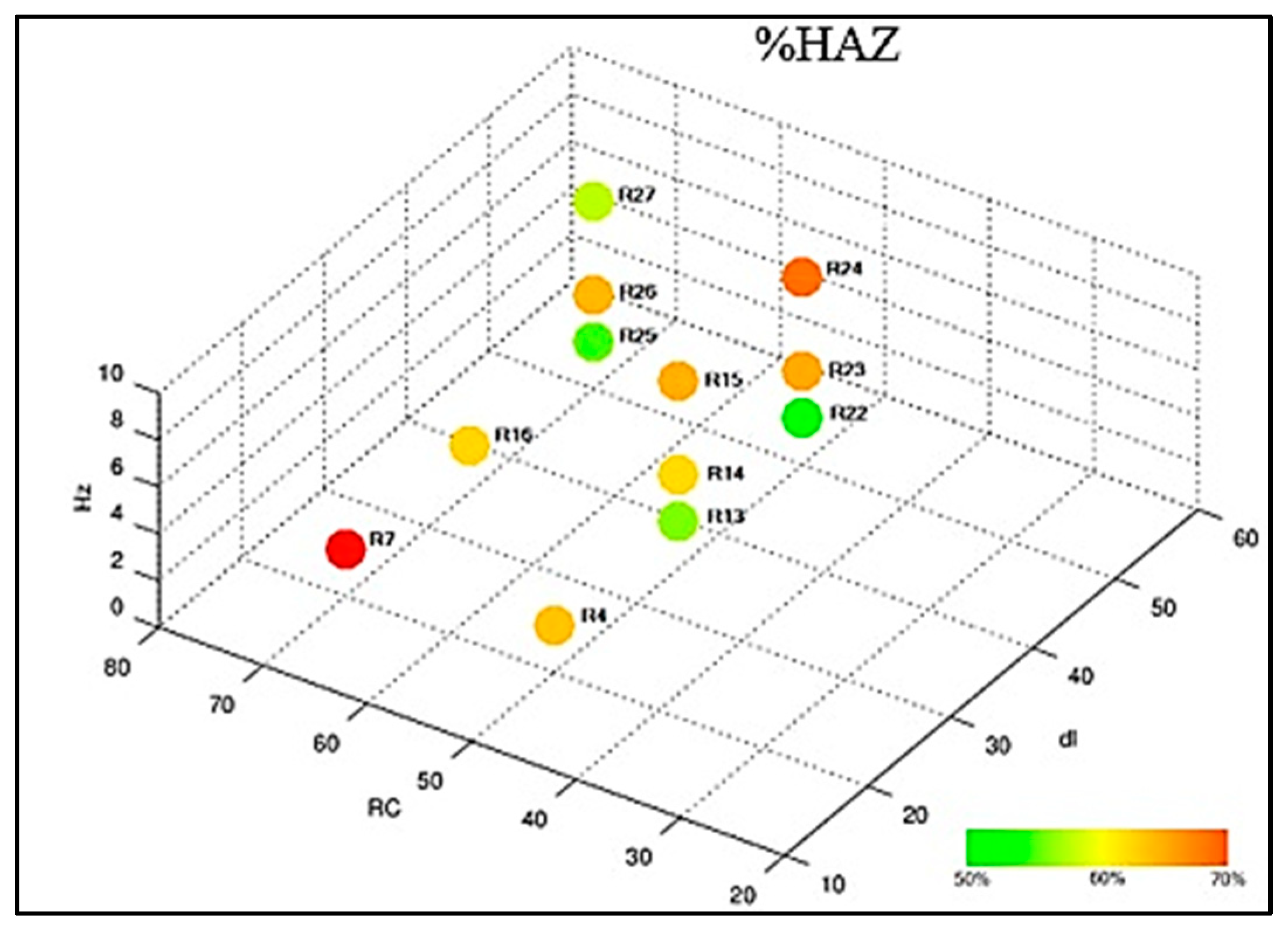
3.3. Variation in Delta I

It is possible to observe that with the increase in the current delta, there is no significant alteration in the tensile strength limit values and percentage elongation; most of the time, these values alternate, making it impossible to determine a characteristic behavior. With regard to the balance, there is a reduction in the percentage values in the balance of ferrite and austenite, both in the HAZ and in the FZ. Furthermore, the appearance of the weld moves from a hole condition to an acceptable condition.

4. Conclusions

More important than getting an ideal adjustment for the pulsed arc setting in the TIG welding process is knowing how to achieve it. From the work conducted, it is possible to define which parameters will need to be adjusted in obtaining the desired results in a more agile and precise way, where the following can be concluded:
The changes with the cyclic relationship were more significant when considering the visual aspect of the weld.
The changes with the frequency were more significant when considering the mechanical property of percentage elongation.
The changes with the current Delta were more significant when considering the ferrite rate in the thermally affected zone.
For the property of limit voltage of tensile strength and ferrite rate in the molten zone region, no results were found that allow the linkage of these variations to the changes of each of the parameters.

5. Importance and Relevance

The present work brought results of paramount importance for the realization of welding on duplex stainless steel tape S31803. The knowledge of the variables associated with good welding quality provides greater robustness for the process, thus avoiding rework and financial losses during the production of the flexible duct.

Author Contributions

Conceptualization, V.M.A.G. and L.M.d.S.; methodology, V.M.A.G., L.M.d.S. and E.C.P.; validation, V.M.A.G. and L.M.d.S.; formal analysis, V.M.A.G., S.N.M. and E.C.P.; investigation, V.M.A.G., L.M.d.S. and E.C.P.; writing—original draft preparation, L.M.d.S. and E.C.P.; writing—review and editing, A.R.G.d.A. and S.N.M.; supervision, A.R.G.d.A., E.C.P. and S.N.M.; project administration, E.C.P.; funding acquisition, A.R.G.d.A. and S.N.M. All authors have read and agreed to the published version of the manuscript.

Funding

This research was funded by the State University of the Northern Fluminense (UENF) and partially financed by CAPES (Coordenação de Aperfeiçoamento de Pessoal de Nível Superior—Brazil), CNPq (Coordenação Nacional de Pesquisa), and FAPERJ (Fundação de Apoio à Pesquisa do Estado do Rio de Janeiro). The participation of A.R.G.A. was sponsored by FAPERJ through the research fellowships proc.no: E-26/210.150/2019, E-26/211.194/2021, E-26/211.293/2021, and E-26/201.310/2021 and by CNPq PQ2 307592/2021-9.

Institutional Review Board Statement

Not applicable.

Informed Consent Statement

Not applicable.

Data Availability Statement

Not applicable.

Conflicts of Interest

The authors declare no conflict of interest.

References

  1. Oliveira, I.P.G.; Luz, T.S. Study of the manufacturing process of UNS 32304 duplex stainless steel flexible pipes used in the oil and gas industry. Soldag. Insp. 2013, 18, 2–11. [Google Scholar] [CrossRef]
  2. Maurya, A.K.; Chhibber, R.; Pandey, C. Heat Input Effect on Dissimilar Super Duplex Stainless Steel (UNS S32750) and Nitronic Steel (N 50) Gas Tungsten Arc Weld: Mechanism, Microstructure, and Mechanical Properties. J. Mater. Eng. Perform. 2023, 32, 5283–5316. [Google Scholar] [CrossRef]
  3. Neto, A.G.; Martin, C.A. Flexible Pipes: Influence of the Pressure Armor in the Wet Collapse Resistance. In Proceedings of the 30th International Conference on Ocean, Offshore and Arctic Engineering, Rotterdam, The Netherlands, 19–24 June 2011; pp. 4–7. [Google Scholar]
  4. Tavares, S.S.M.; Scandian, C.; Pardal, J.M.; Luz, T.S.; Silva, F.J. Failure analysis of duplex stainless steel weld used in flexible pipes in off shore oil production. Eng. Fail. Anal. 2010, 6, 1500–1506. [Google Scholar] [CrossRef]
  5. Michalska, J.; Sozanska, M. Qualitative and quantitative analysis of σ and χ phases in 2205 duplex stainless steels. Mater. Charact. 2006, 56, 355–362. [Google Scholar] [CrossRef]
  6. Wainer, E.; Brandi, S.D.; Mello, F.D.H. Welding Processes and Metallurgy, 6th ed.; Wiley Online Library: New York, NY, USA, 2008. [Google Scholar]
  7. Liu, J.; Niu, H.; He, Y.; Zhang, Y.; Sun, X. Research on Welding Process of Duplex Stainless Steel S31803. J. Physics. Conf. Ser. 2023, 2469, 12007. [Google Scholar] [CrossRef]
  8. Wang, J.; Lu, M.; Zhang, L.; Chang, W.; Xu, L.; Hu, L. Effect of welding process on the microstructure and properties of dissimilar weld joints between low alloy steel and duplex stainless steel. Int. J. Miner. Metall. Mater. 2012, 19, 518–524. [Google Scholar] [CrossRef]
  9. Ferreira, J.A. Good practices in welding Duplex and Superduplex Stainless Steels, using the GTAW process. ENSOLD 2012, 4–9. [Google Scholar]
  10. Loureiro, J.P. Characterization of Duplex Stainless Steel UNS S31803 by the Non-Destructive Technique of Pulsed Eddy Currents. Bachelor’s Thesis, Universidade do Rio de Janeiro, Rio de Janeiro, Brazil, 2010. pp. 20–25. [Google Scholar]
  11. Silva, A.L.V.C.; Mei, P.R. Special Steels and Alloys, 3rd ed.; Editora Edgard Blücher: São Paulo, Brazil, 2011; 664p, ISBN 9788521205180. [Google Scholar]
  12. Lo, K.; Shek, C.; Lai, J. Recent developments in stainless steels. Mater. Sci. Eng. R Rep. 2009, 65, 39–104. [Google Scholar] [CrossRef]
  13. Honggang, Z.; Xiangru, C.; Lu, A.; Qijie, Z. Effect of cooling rate on solidification structure and linear contraction of a duplex stainless steel. Res. Amp. Dev. 2012, 9, 239–243. [Google Scholar]
  14. Senatore, M.; Finzetto, L.; Perea, E. Comparative study between duplex stainless steel and the stainless AISI 304L/316L. Rev. Esc. De Minas 2007, 60, 175–181. [Google Scholar] [CrossRef]
  15. Gunn, R.N. Duplex Stainless Steels—Microstructure, Properties and Applications; Woodhead Publishing Ltd.: Cambridge, UK, 1997; 204p. [Google Scholar]
  16. Armas, I.A.; Moreuil, S.D. Duplex Stainless Steels; ISTE Ltd.: London, UK; John Wiley & Sons Inc.: Hoboken, NJ, USA, 2009; 447p. [Google Scholar]
  17. Yuan, J.T.; Zhang, H.H.; Fu, A.Q.; Yin, C.X.; Zhu, M.; Lv, N.X.; Xu, X.Q.; Miao, J. Insights into the corrosion perforation of UNS S32205 duplex stainless steel weld in gas transportation pipelines. Mater. Corros. 2017, 68, 858–867. [Google Scholar] [CrossRef]
  18. Quackatz, L.; Griesche, A.; Kannengiesser, T. In situ investigation of chemical composition during TIG welding in duplex stainless steels using Laser-Induced Breakdown Spectroscopy (LIBS). Forces Mech. 2022, 6, 100063. [Google Scholar] [CrossRef]
  19. Kliauga, A.M.; Pohl, M. Effect of plasma nitriding on wear and pitting corrosion resistance of X2 CrNiMoN 2205 3 duplex stainless steel. Surf. Coat. Technol. 1998, 98, 1205–1210. [Google Scholar] [CrossRef]
  20. Moura, V.S.; Lima, D.L.; Pardal, M.J.; Kina, A.Y.; Corte, R.R.A.; Tavares, S.S.M. Influence of microstructure on the corrosion resistance of the duplex stainless steel UNS S31803. Mater. Charact. 2008, 59, 1127–1132. [Google Scholar] [CrossRef]
  21. Deng, B.; Jiang, Y.M.; Gao, J.; Li, J. Effect of annealing treatment on microstructure evolution and the associated corrosion behavior of a super-duplex stainless steel. J. Alloys Compd. 2010, 493, 461–464. [Google Scholar] [CrossRef]
  22. Zhang, Z.; Wang, Z.; Jiang, Y.; Tan, H.; Han, D.; Guo, Y.; Li, J. Effect of post-weld heat treatment on microstructure evolution and pitting corrosion behavior of UNS S 31803 duplex stainless steel. Corros. Sci. 2012, 62, 42–50. [Google Scholar] [CrossRef]
  23. Bracarense, A.Q. TIG Welding Process—GTAW. 2000; pp. 8–11. [Google Scholar]
  24. Wang, A.; Chiu, P.K.; Yang, J.; Fang, J. Gamma phase transformation in pulsed GTAW weld metal of duplex stainless steel. Mater. Sci. Eng. A 2006, 420, 26–33. [Google Scholar] [CrossRef]
  25. Mondal, S.; Nandi, G.; Pal, P.K. Parametric optimization of TIG welding of duplex stainless steel without filler rod by PCA method. In Proceedings of the IOP Conference Series: Materials Science and Engineering, Sanya, China, 12–14 November 2021; p. 1017. [Google Scholar]
  26. Liao, J. Nitride precipitation in weld TAZs of a duplex stainless steel. ISIJ Int. 2001, 41, 460–467. [Google Scholar] [CrossRef]
  27. Souza, D.D.B.G.; Vilarinho, L.O.; Hubner, H.B. Quantitative Analysis of the Phases Present in Duplex Stainless Steel UNS S31803 Welded by the Conventional Short-Circuit MIG/MAG Process. Weld. Insp. 2019, 25. [Google Scholar]
  28. ASME Boiler and Pressure Vessel Code, Qualification Standard for Welding and Brazing Procedures, Welders, Brazers, and Welding and Brazing Operators; Section IX, 187; ASME: New York, NY, USA, 2018.
  29. Fraga, F.B. Weldability Studies and Parameter Optimization with 2205 Duplex Stainless Steel Rolled Using the Autogenous TIG Process. Master’s Thesis, Federal Institute of Espírito Santo—IFES, Vitória, ES, Brazil, 2017; 187p. [Google Scholar]
  30. Pinheiro, F.W. Effect of Thermal Solubilization Treatment on Microstructure and Corrosion Resistance of Joints Welded with The Autogenous Tig Process in Stainless Steel Duplex Uns S31803. Master’s Thesis, Universidade Estadual do Norte Fluminense Darcy Ribeiro—UENF, Campos dos Goytacazes, Brazil, 2021; 123p. [Google Scholar]
  31. Souza, L.M.; Pereira, E.C. Structure, Properties and Characterization of Duplex Stainless Steel s31803 Subjected to Corrosive Media of Hydrochloric Acid, Ferric Chloride and Sulfuric Acid. Master’s Thesis, State University of Norte Fluminense Darcy Ribeiro—UENF, Campos dos Goytacazes, Brazil, 2020; 115p. [Google Scholar]
Figure 1. Current graph for the pulsed source.
Materials 16 06870 g001
Figure 2. Experimental steps.
Materials 16 06870 g002
Figure 3. (a) Weld image at 10×; (b) Weld image at 50×; (c) 200× image with definition of the weld regions (region highlighted in (b)).
Materials 16 06870 g003
Figure 4. (a) Representation of the waveform of tuning number 17 (tuning with all parameters at their average values); (b) Representation of the maximum current variation during the experiments; (c) Representation of the maximum variation in the wave’s cyclical relation during the experiments; (d) Representation of waveform variation during experiments; (e) Representation of the pulse frequency variation.
Materials 16 06870 g004
Figure 5. Weld without the appearance of fusion at the root (highlighted).
Materials 16 06870 g005
Figure 6. Weld with holes in the weld region.
Materials 16 06870 g006
Figure 7. Weld with satisfactory visual appearance.
Materials 16 06870 g007
Figure 8. Compilation of visual appearance results.
Materials 16 06870 g008
Figure 9. Compilation of tension results.
Materials 16 06870 g009
Figure 10. Compilation of elongation results.
Materials 16 06870 g010
Figure 11. Bending view of the pulled face.
Materials 16 06870 g011
Figure 12. Bending view of the pulled root.
Materials 16 06870 g012
Figure 13. Compilation of ferrite count results in the HAZ.
Materials 16 06870 g013
Figure 14. Compilation of ferrite count results at FZ.
Materials 16 06870 g014
Table 1. Composition (% by weight) of the UNS S31803 duplex stainless steel strip in percentages [13].
ElementCMnSiCrNiPSMo
%0.032.01.021.0–23.04.5–6.50.030.022.5–3.5
Table 2. Mechanical properties of UNS S31803 duplex stainless steel [13].
UNSσp0.2(MPa)σm(MPa)A%
S3180345062025
Table 3. Adjustment proposals for the study itinerary.
AdjustmentDelta I (A)CR (%)Frequency (Hz)Peak Current (A)Base Current (A)Torch Speed (mm/min)
12030218036250
22030418036250
32030818036250
42050218036250
52050418036250
62050818036250
72070218036250
82070418036250
92070818036250
103530216056250
113530416056250
123530816056250
133550216056250
143550416056250
153550816056250
163570216056250
173570416056250
183570816056250
195030214472250
205030414472250
215030814472250
225050214472250
235050414472250
245050814472250
255070214472250
265070414472250
275070814472250
Table 4. Results matrix.
AdjustmentVisual AspectS1S2S3S4S5
Tension (MPa)Elong. (%)Tension (MPa)Elong. (%)Bending% Ferrite FZ% Ferrite HAZ
1Rootless--------
2Rootless--------
3Hole--------
4Good759.1214744.6910OKOK54.3261.14
5Hole--------
6Hole--------
7Good753.1513740.5211OKOK63.1467.04
8Hole--------
9Hole--------
10Rootless--------
11Rootless--------
12Rootless--------
13Good758.8414758.4116OKOK5256.46
14Good775.7713742.989OKOK53.9560.39
15Good752.418750.309OKOK56.5461.83
16Good743.4912735.3810OKOK63.0560.55
17Hole--------
18Hole--------
19Rootless--------
20Rootless--------
21Rootless--------
22Good766.1918761.7028OKOK48.8653.32
23Good768.3527759.2926OKOK53.5162.02
24Good747.310747.8810OKOK55.8563.95
25Good753.0816756.7716OKOK54.4255.60
26Good770.2228749.0415OKOK53.6261.55
27Good737.298734.578OKOK53.6457.60
Table 5. Definition of interest groups.
Frequency Study, Maintaining RC And Delta I
Group123456789
N° Regions1,2 e 34, 5 e 67, 8 e 910, 11 e 1213, 14 e 1516, 17 e 1819, 20 e 2122, 23 e 2425, 26 e 27
CR Study, Maintaining Frequency And Delta I
Group101112131415161718
N° Regions1, 4 e 72, 5 e 83, 6 e 910, 13 e 1611, 14 e 1712, 15 e 1819, 22 e 2520, 23 e 2621, 24 e 27
Delta I Study, Maintaining RC And Frequency
Group19202222324252627
N° Regions1, 10 e 192, 11 e 203, 12 e 214, 13 e 225, 14 e 236, 15 e 247, 16 e 258, 17 e 269, 18 e 27
Disclaimer/Publisher’s Note: The statements, opinions and data contained in all publications are solely those of the individual author(s) and contributor(s) and not of MDPI and/or the editor(s). MDPI and/or the editor(s) disclaim responsibility for any injury to people or property resulting from any ideas, methods, instructions or products referred to in the content.

