
Material Extrusion to Manufacture Carbide-Based Advanced Cutting Tools


Abstract
:1. Introduction
2. Materials and Methods
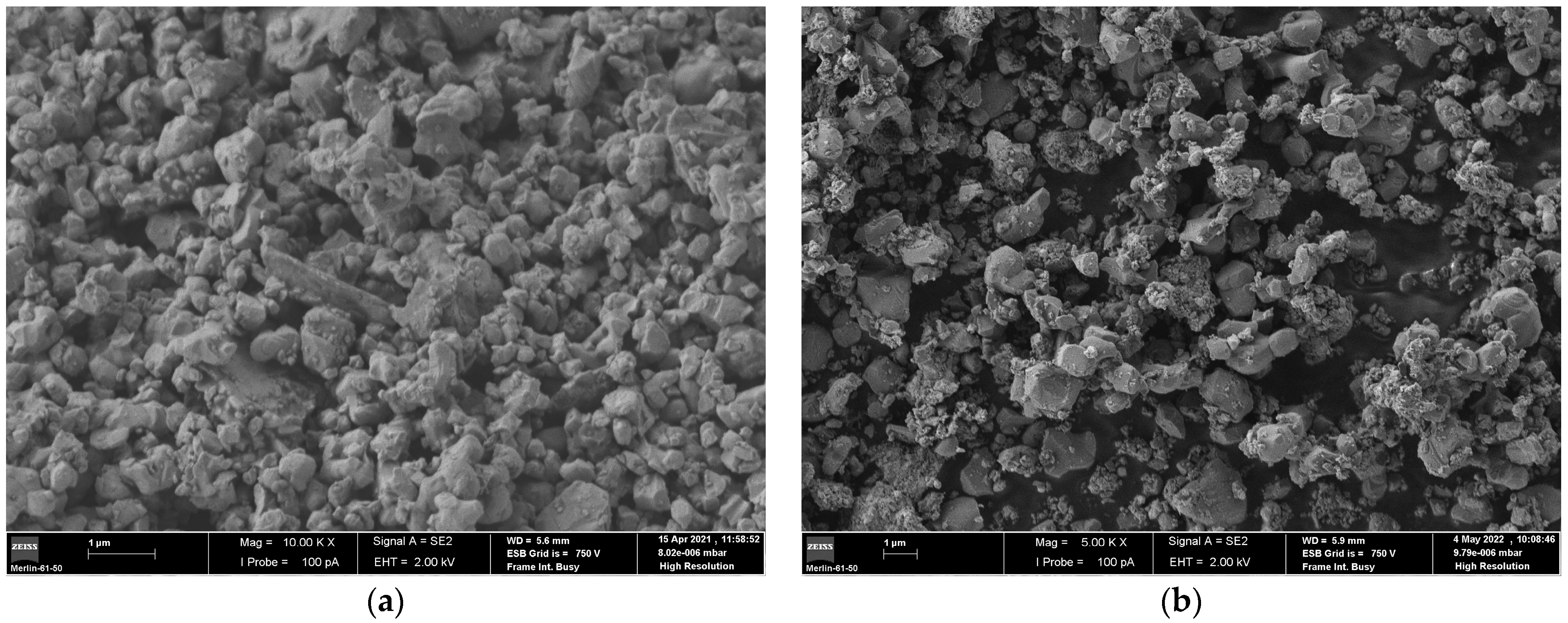
2.1. Powder, Binder, and Additives
2.2. Processing
2.3. Debinding and Sintering
2.4. Characterization Techniques
3. Results and Discussion
3.1. Feedstock and Filaments
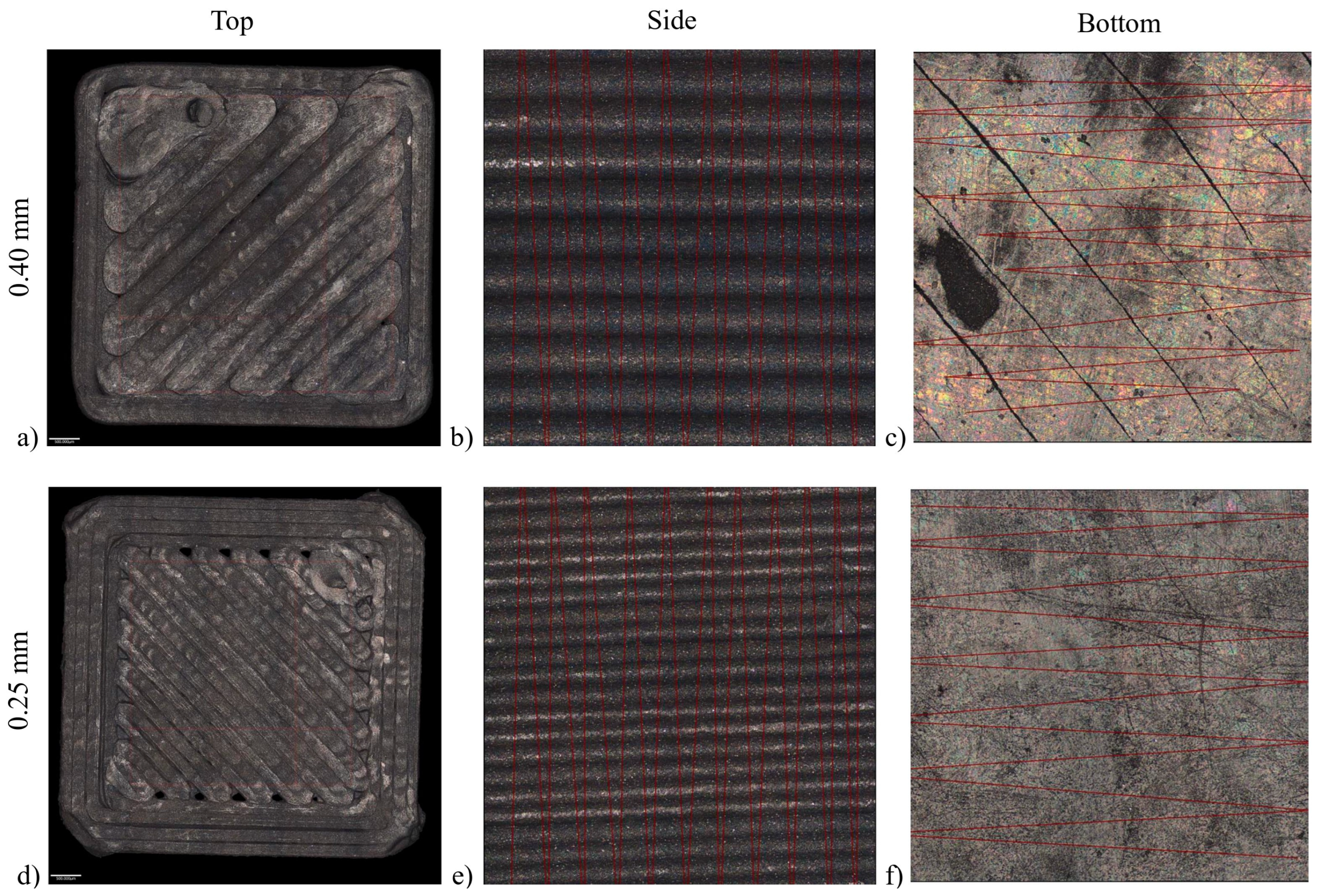
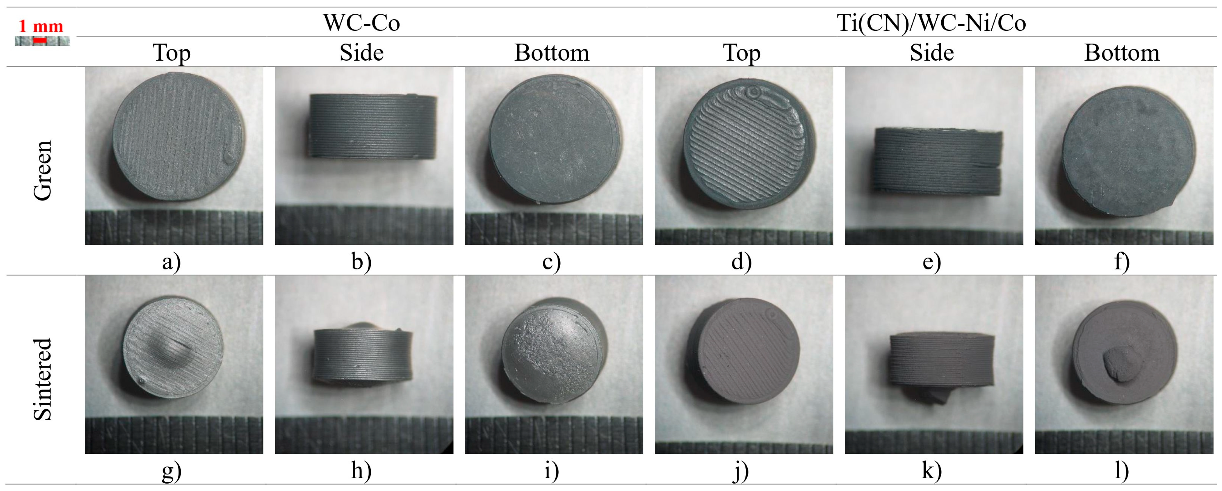
3.2. The 3D Object Surface Roughness
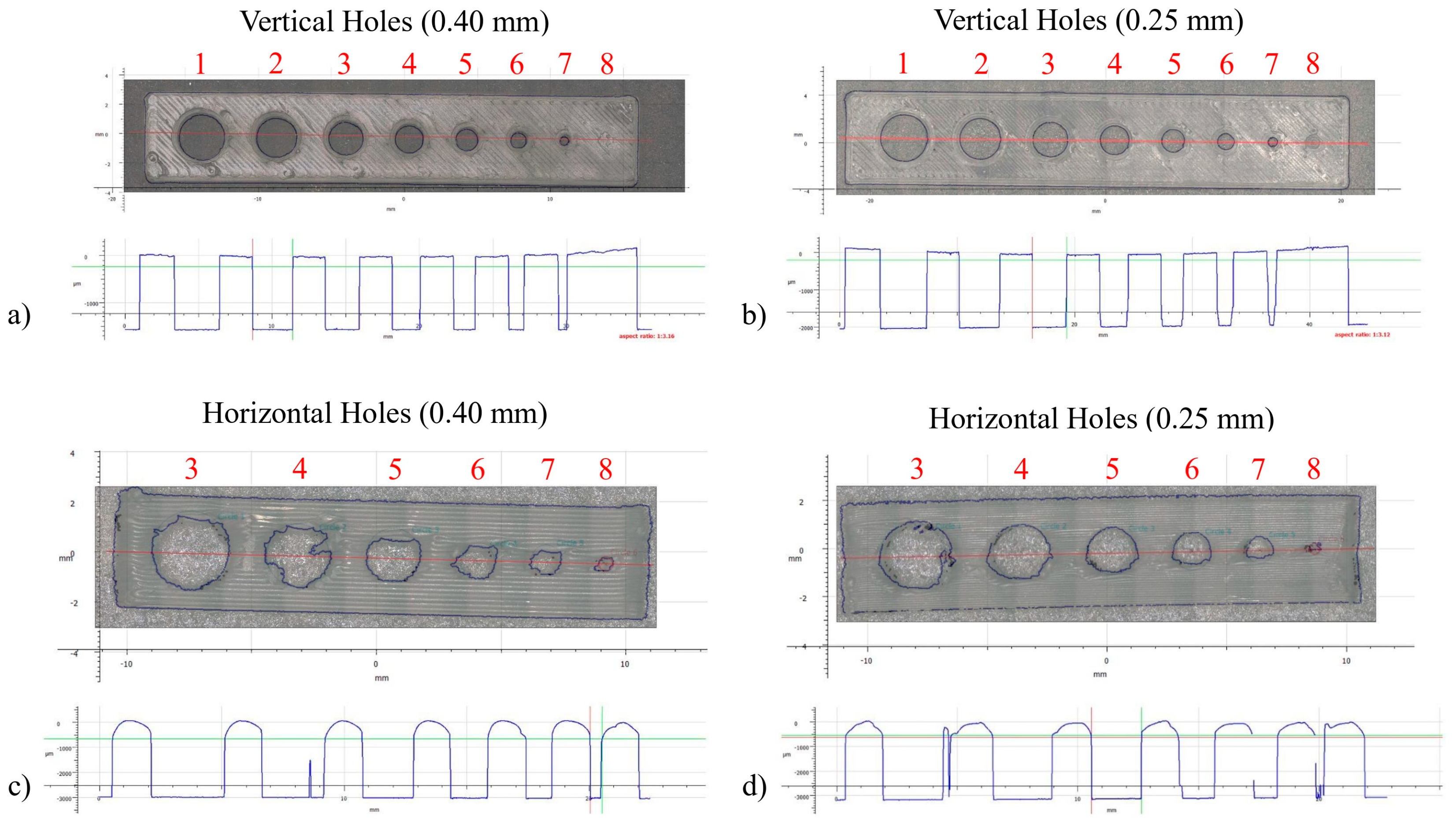
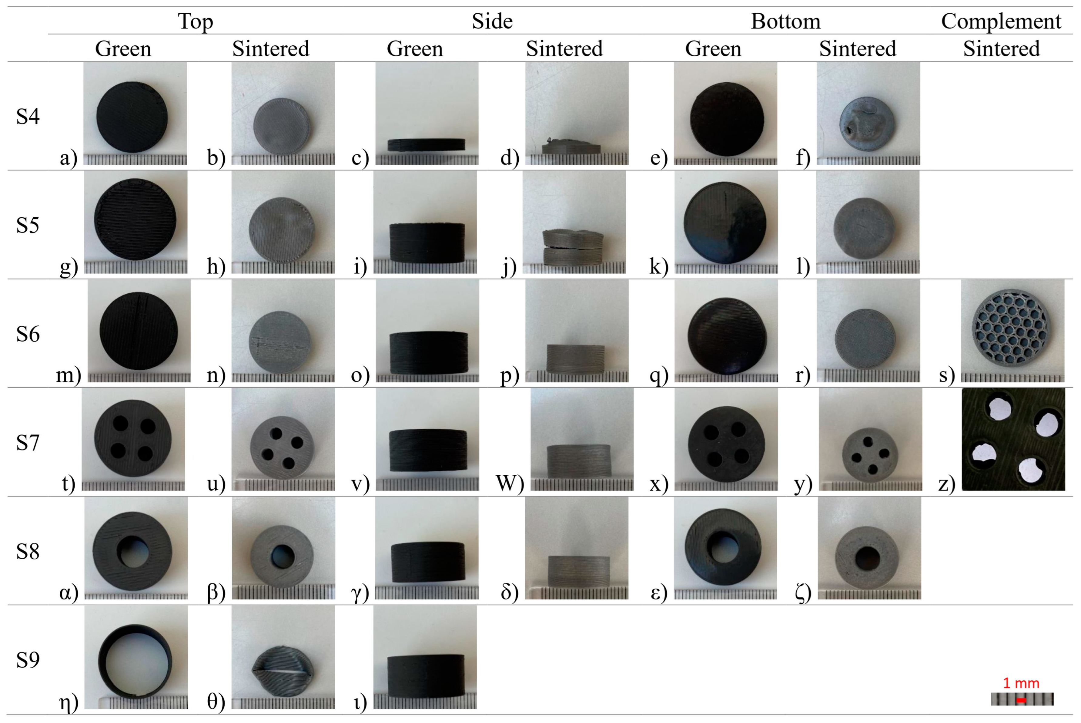
3.3. Hole Size and Orientation
3.4. Defects
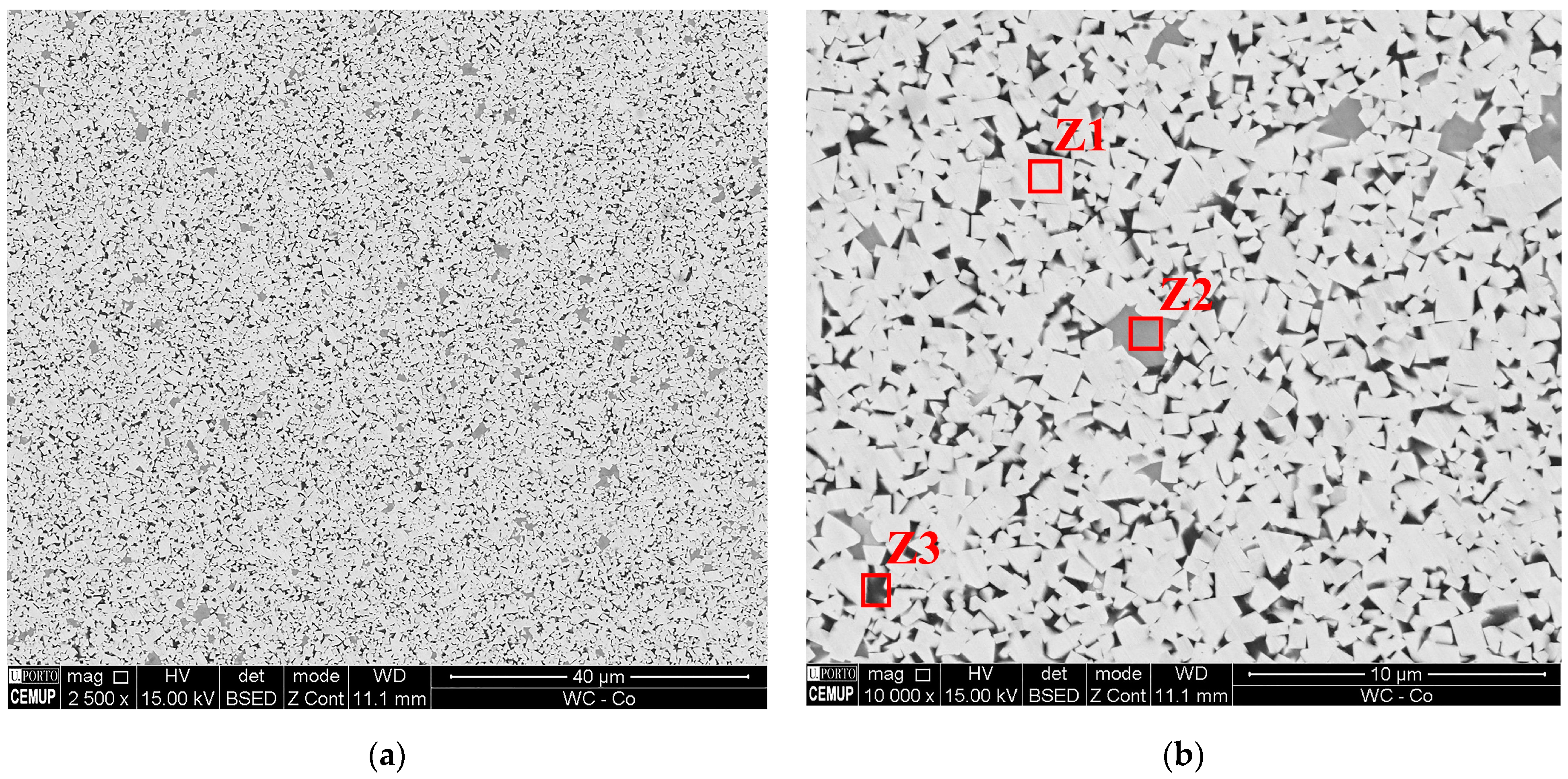
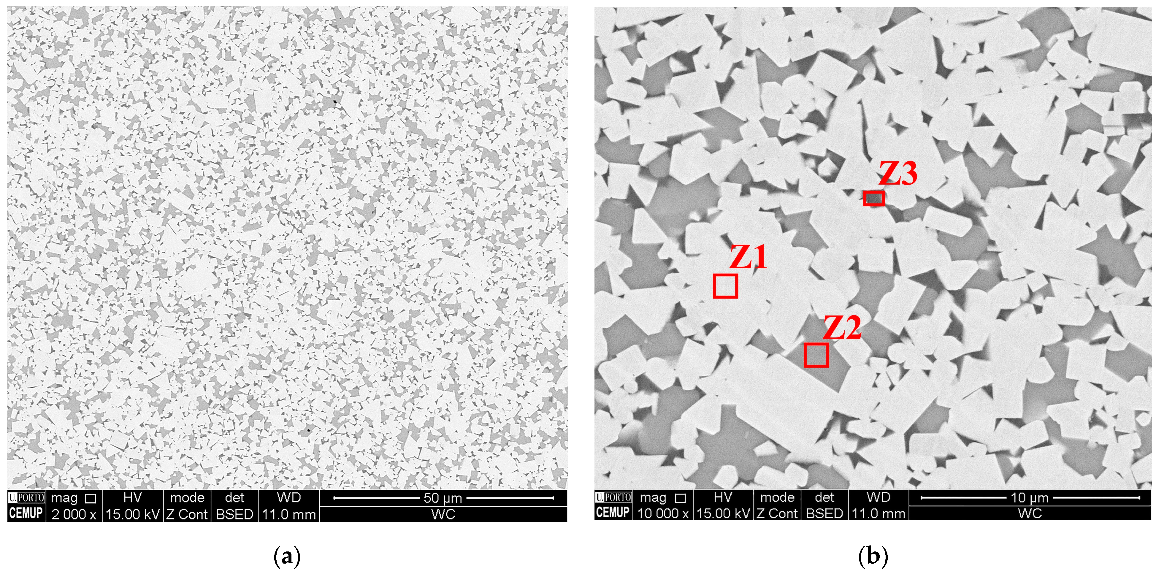
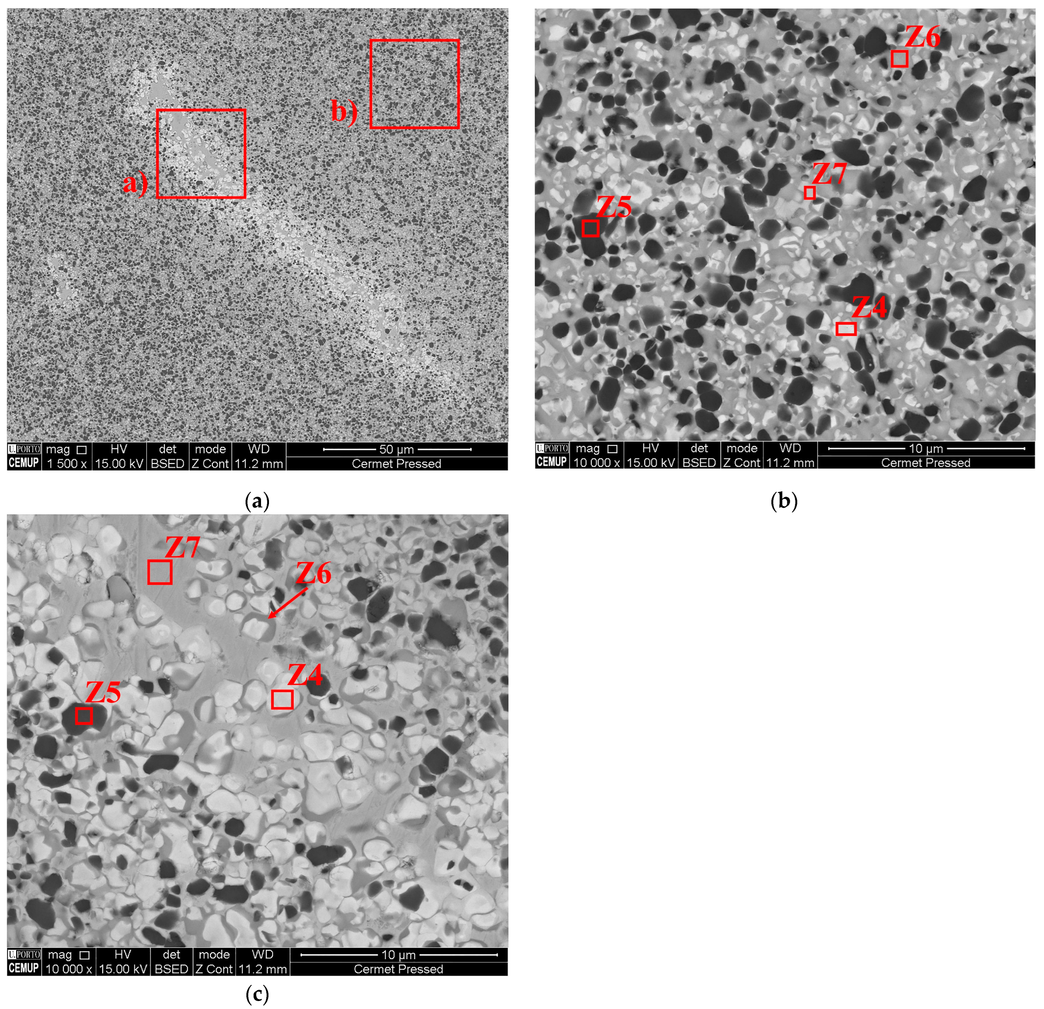
3.5. Microstructure
4. Conclusions
Author Contributions
Funding
Institutional Review Board Statement
Informed Consent Statement
Data Availability Statement
Conflicts of Interest
Nomenclature
| MEX | Material extrusion |
| AM | Additive manufacturing |
| PBF | Powder bed fusion |
| BJT | Binder jetting |
| VPP | Vat photopolymerization |
| SLS | Selective laser sintering |
| SEM | Scanning electron microscopy |
| TGA | Thermogravimetric |
| TPE | Thermoplastic elastomer |
| PP | Polypropylene |
| RTP | Ready-to-press |
| PW | Paraffin wax |
| PEC | Poly(propylene-ethylene) copolymer |
| PA | Polyamide |
| SA | Stearic acid |
| PIM | Powder injection moulding |
| IFM | Infinite focus measurement |
References
- Metal Cutting Tools Market Size|Global Industry Report, [2020–2027]. Available online: https://www.fortunebusinessinsights.com/industry-reports/metal-cutting-tools-market-101751 (accessed on 10 May 2022).
- 3D Printing Market Size, Growth|Global Research Report [2029]. Available online: https://www.fortunebusinessinsights.com/industry-reports/3d-printing-market-101902 (accessed on 10 May 2022).
- Machining Market to Reach $414.17 Billion by 2022, Says Beroe Inc. Available online: https://www.prnewswire.com/news-releases/machining-market-to-reach-414-17-billion-by-2022--says-beroe-inc-300939464.html (accessed on 22 June 2022).
- Aramian, A.; Razavi, S.M.J.; Sadeghian, Z.; Berto, F. A Review of Additive Manufacturing of Cermets. Addit. Manuf. 2020, 33, 101130. [Google Scholar] [CrossRef]
- Yang, Y.; Zhang, C.; Wang, D.; Nie, L.; Wellmann, D.; Tian, Y. Additive Manufacturing of WC-Co Hardmetals: A Review. Int. J. Adv. Manuf. Technol. 2020, 108, 1653–1673. [Google Scholar] [CrossRef]
- Heydari, L.; Lietor, P.F.; Corpas-Iglesias, F.A.; Laguna, O.H. Ti(C,N) and WC-Based Cermets: A Review of Synthesis, Properties and Applications in Additive Manufacturing. Materials 2021, 14, 6786. [Google Scholar] [CrossRef] [PubMed]
- Uhlmann, E.; Bergmann, A.; Gridin, W. Investigation on Additive Manufacturing of Tungsten Carbide-Cobalt by Selective Laser Melting. Procedia CIRP 2015, 35, 8–15. [Google Scholar] [CrossRef]
- Cavaleiro, A.J.; Fernandes, C.M.; Farinha, A.R.; Gestel, C.V.; Jhabvala, J.; Boillat, E.; Senos, A.M.R.; Vieira, M.T. The Role of Nanocrystalline Binder Metallic Coating into WC after Additive Manufacturing. Appl. Surf. Sci. 2018, 427, 131–138. [Google Scholar] [CrossRef]
- Ku, N.; Pittari, J.J.; Kilczewski, S.; Kudzal, A. Additive Manufacturing of Cemented Tungsten Carbide with a Cobalt-Free Alloy Binder by Selective Laser Melting for High-Hardness Applications. JOM 2019, 71, 1535–1542. [Google Scholar] [CrossRef]
- Fries, S.; Genilke, S.; Wilms, M.B.; Seimann, M.; Weisheit, A.; Kaletsch, A.; Bergs, T.; Schleifenbaum, J.H.; Broeckmann, C. Laser-Based Additive Manufacturing of WC–Co with High-Temperature Powder Bed Preheating. Steel Res. Int. 2020, 91, 1900511. [Google Scholar] [CrossRef]
- Padmakumar, M. Additive Manufacturing of Tungsten Carbide Hardmetal Parts by Selective Laser Melting (SLM), Selective Laser Sintering (SLS) and Binder Jet 3D Printing (BJ3DP) Techniques. Lasers Manuf. Mater. Process. 2020, 7, 338–371. [Google Scholar] [CrossRef]
- Al-Thamir, M.; McCartney, D.G.; Simonelli, M.; Hague, R.; Clare, A. Processability of Atypical WC-Co Composite Feedstock by Laser Powder-Bed Fusion. Materials 2020, 13, 50. [Google Scholar] [CrossRef]
- Lisiecki, A.; Ślizak, D. Hybrid Laser Deposition of Composite WC-Ni Layers with Forced Local Cryogenic Cooling. Materials 2021, 14, 4312. [Google Scholar] [CrossRef]
- Sykora, J.; Sedlmajer, M.; Schubert, T.; Merkel, M.; Kroft, L.; Kucerova, L.; Rehor, J. Additive Manufacturing of WC-Co Specimens with Internal Channels. Materials 2023, 16, 3907. [Google Scholar] [CrossRef] [PubMed]
- Wolfe, T.A.; Enneti, R.K.; Shah, R.M.; Prough, K.C.; Trasorras, J.L. Binder Jetting 3D Printed Cemented Carbide: Mechanical and Wear Properties of Medium and Coarse Grades. In Proceedings of the 20th Plansee Seminar, Reutte, Austria, 30 May–3 June 2022; pp. 1–14. [Google Scholar]
- Prichard, P.D.; Wang, Z.; Miyanaji, H. Microstructural Development in Binder Jet Additive Manufacturing of WC-Co. In Proceedings of the 20th Plansee Seminar, Reutte, Austria, 30 May–3 June 2022; pp. 1–14. [Google Scholar]
- Cabezas, L.; Berger, C.; Jiménez-Piqué, E.; Pötschke, J.; Llanes, L. Testing Length-Scale Considerations in Mechanical Characterization of WC-Co Hardmetal Consolidated by Binder Jetting Additive Manufacturing. In Proceedings of the 20th Plansee Seminar, Reutte, Austria, 30 May–3 June 2022; pp. 1–11. [Google Scholar]
- Lengauer, W.; Duretek, I.; Fürst, M.; Schwarz, V.; Gonzalez-Gutierrez, J.; Schuschnigg, S.; Kukla, C.; Kitzmantel, M.; Neubauer, E.; Lieberwirth, C.; et al. Fabrication and Properties of Extrusion-Based 3D-Printed Hardmetal and Cermet Components. Int. J. Refract. Met. Hard Mater. 2019, 82, 141–149. [Google Scholar] [CrossRef]
- Berger, C.; Abel, J.; Pötschke, J.; Moritz, T. Properties of Additive Manufactured Hardmetal Components Produced by Fused Filament Fabrication (FFF). In Proceedings of the Euro PM 2018 Congress and Exhibition, Bilbao, Spain, 14–18 October 2018; pp. 6–11. [Google Scholar]
- Agarwala, M.K.; van Weeren, R.; Bandyopadhyay, A.; Whalen, P.J.; Safari, A.; Danforth, S.C. Fused Deposition of Ceramics and Metals: An Overview. In Proceedings of the 1996 International Solid Freeform Fabrication Symposium, Austin, TX, USA, 12–14 August 1996; pp. 1–8. [Google Scholar]
- Zhang, X.; Guo, Z.; Chen, C.; Yang, W. Additive Manufacturing of WC-20Co Components by 3D Gel-Printing. Int. J. Refract. Met. Hard Mater. 2018, 70, 215–223. [Google Scholar] [CrossRef]
- Lengauer, W.; Duretek, I.; Fiirst, M.; Gonzalez-Gutierrez, J.; Schuschnigg, S.; Kukla, C. Fused-Filament Printing of Hardmetals and Cermets with Feedstock from RTP Powders. In Proceedings of the Euro PM2019, Maastricht, The Netherlands, 13–16 October 2019; pp. 15–20. [Google Scholar]
- Bose, A.; Reidy, J.; Jorgensen, L.; Tuncer, N.; Enneti, R.; Jewett, T.; Trasorras, J.L.; Wolfe, T. Bound Metal Deposition of Cemented Tungsten Carbide. In Proceedings of the 20th Plansee Seminar, Reutte, Austria, 30 May–3 June 2022; pp. 1–12. [Google Scholar]
- Gestrich, T.; Pötschke, J.; Mayer, M.; Berger, C.; Abel, J.; Gruner, D.; Kaiser, A. Analysis of Debinding and Sintering of Additive Manufactured Green Bodies of Cemented Carbides. In Proceedings of the 20th Plansee Seminar, Reutte, Austria, 30 May–3 June 2022; pp. 1–10. [Google Scholar]
- Bartolo, P.J.; Gaspar, J. Metal Filled Resin for Stereolithography Metal Part. CIRP Ann. Manuf. Technol. 2008, 57, 235–238. [Google Scholar] [CrossRef]
- Chychko, A.; García, J.; Collado Ciprés, V.; Holmström, E.; Blomqvist, A. HV-KIC Property Charts of Cemented Carbides: A Comprehensive Data Collection. Int. J. Refract. Met. Hard Mater. 2022, 103, 105763. [Google Scholar] [CrossRef]
- García, J.; Collado Ciprés, V.; Blomqvist, A.; Kaplan, B. Cemented Carbide Microstructures: A Review. Int. J. Refract. Met. Hard Mater. 2019, 80, 40–68. [Google Scholar] [CrossRef]
- Clemente, M.R.; Oliveira Panão, M.R. Introducing Flow Architecture in the Design and Optimization of Mold Inserts Cooling Systems. Int. J. Therm. Sci. 2018, 127, 288–293. [Google Scholar] [CrossRef]
- Clemente, M.R.; Panão, M.R.; Pascoal-Faria, P.; Alves, N. Micro-Cooling Constructal Design: An Application to Mold Inserts Thermal Management. AIP Conf. Proc. 2018, 1978, 5043816. [Google Scholar] [CrossRef]
- Bejan, A.; Lorente, S. Design with Constructal Theory; John Wiley & Sons, Inc.: Hoboken, NJ, USA, 2008; ISBN 9780471998167. [Google Scholar]
- Shaw, M.C. Metal Cutting Principles, 2nd ed.; Oxford University Press, Inc.: New York, NY, USA, 2005; ISBN 0195142063. [Google Scholar]
- Childs, T.; Maekawa, K.; Obikawa, T.; Yamane, Y. Metal Machining—Theory and Applications; First.; John Wiley & Sons Inc.: New York, NY, USA, 2000; ISBN 0 470 39245 2. [Google Scholar]
- Augspurger, T.; Klocke, F.; Döbbeler, B.; Brockmann, M.; Gierlings, S.; Lima, A. Modeling of Transient Thermal Conditions in Cutting. J. Mech. Eng. Autom. 2017, 7. [Google Scholar] [CrossRef]
- Yağmur, S. The Effects of Cooling Applications on Tool Life, Surface Quality, Cutting Forces, and Cutting Zone Temperature in Turning of Ni-Based Inconel 625. Int. J. Adv. Manuf. Technol. 2021, 116, 821–833. [Google Scholar] [CrossRef]
- Bartoszuk, M. Approximately Model of the Maximum Temperature on the Chip Surface. Materials 2021, 14, 2592. [Google Scholar] [CrossRef] [PubMed]
- Stephenson, D.A.; Agapiou, J.S. Metal Cutting Theory and Pratice, 3rd ed.; Taylor & Francis Group, LLC: Boca Raton, FL, USA, 2016; ISBN 13: 978-1-4665-8754-0. [Google Scholar]
- Cerejo, F.; Silva, A.; Vieira, M.F.; Barreiros, F.M. Fused Deposition of WC + Co Powder. In Proceedings of the Euro PM2019, Maastricht, The Netherlands, 13–16 October 2019. [Google Scholar]
- ISO/ASTM 52900:2015; Additive Manufacturing—General Principles—Terminology. ISO: Geneva, Switzerland, 2021.
- Carrillo, G.; Keck, D.; Martinez-Duarte, R. Mechanical Properties and Process Improvement of Tungsten Carbide Additively Manufactured with Renewable Biopolymers. Procedia Manuf. 2019, 34, 704–711. [Google Scholar] [CrossRef]
- Straumal, B.B.; Shchur, L.N.; Kagramanyan, D.G.; Konstantinova, E.P.; Druzhinin, A.V.; Nekrasov, A.N. Topology of WC/Co Interfaces in Cemented Carbides. Materials 2023, 16, 5560. [Google Scholar] [CrossRef] [PubMed]
- Heaney, D.F. Handbook of Metal Injection Molding, 2nd ed.; Woodhead Publishing: Duxford, UK, 2019; ISBN 978-0-08-102809-4. [Google Scholar]
- German, R.M.; Bose, A. Injection Molding of Metals and Ceramics, 1st ed.; Metal Powder Industries Federation: Princeton, NJ, USA, 1997; ISBN 1-878954-61-X. [Google Scholar]
- Kim, H.; Kim, J.I.; Do Kim, Y.; Jeong, H.; Ryu, S.S. Material Extrusion-Based Three-Dimensional Printing of WC–Co Alloy with a Paste Prepared by Powder Coating. Addit. Manuf. 2022, 52, 102679. [Google Scholar] [CrossRef]
- Olabisi, O.; Adewale, K. Handbook of Thermoplastics, 2nd ed.; Taylor & Francis Group, LLC: Boca Raton, FL, USA, 2016; ISBN 13 978-1-4665-7723-7. [Google Scholar]
- Utracki, L.A.; Wilkie, C.A. Polymer Blends Handbook, 2nd ed.; Kluwer Academic Publishers: Dordrecht, The Netherlands, 2014; ISBN 978-94-007-6063-9. [Google Scholar]
- ISO 13320:2020 (E). Available online: https://www.iso.org/standard/69111.html (accessed on 29 August 2023).
- ISO 21920-3:2021. Available online: https://www.iso.org/standard/72228.html (accessed on 29 August 2023).
- ISO 25178-2:2021. Available online: https://www.iso.org/standard/74591.html (accessed on 29 August 2023).
- ImageJ. Available online: https://imagej.nih.gov/ij/download.html (accessed on 29 August 2023).


| Powder | Specific Weight (Kg/m3) | D10 (µm) | D50 (µm) | D90 (µm) | Metal Binder (wt.%) |
|---|---|---|---|---|---|
| WC-Co | 14,250 ± 100 | 0.82 | 1.74 | 4.63 | 10 |
| Ti(CN)/WC-Ni/Co | 6600 ± 50 | 1.15 | 2.13 | 3.81 | 15 |
| Powder [vol.%] | Organic Binder [vol.%] | ||
|---|---|---|---|
| 50 | 50 | ||
| PW | PEC and PA | SA | |
| 40 | 50 | 10 | |
| Shape | Dimension [mm] | Nozzle Diameter [mm] | Infill [%] | Hole Diameter [mm] | Material | |
|---|---|---|---|---|---|---|
| C1 | Cube [L W H] | 6.00 × 6.00 × 6.00 | 0.40 | 100 | - | WC + Co |
| C2 | Cube [L W H] | 6.00 × 6.00 × 6.00 | 0.25 | 100 | - | WC + Co |
| V1 | Rect. 1 [L W H] | 43.00 × 8.00 × 2.00 | 0.40 | 100 | 4.00 to 0.50 (8 holes) | WC + Co |
| V2 | Rect. 1 [L W H] | 43.00 × 8.00 × 2.00 | 0.25 | 100 | 4.00 to 0.50 (8 holes) | WC + Co |
| H3 | Rect. 1 [L W H] | 21.70 × 3.00 × 4.60 | 0.40 | 100 | 3.00 to 0.50 (6 holes) | WC + Co |
| H4 | Rect. 1 [L W H] | 21.70 × 3.00 × 4.60 | 0.25 | 100 | 3.00 to 0.50 (6 holes) | WC + Co |
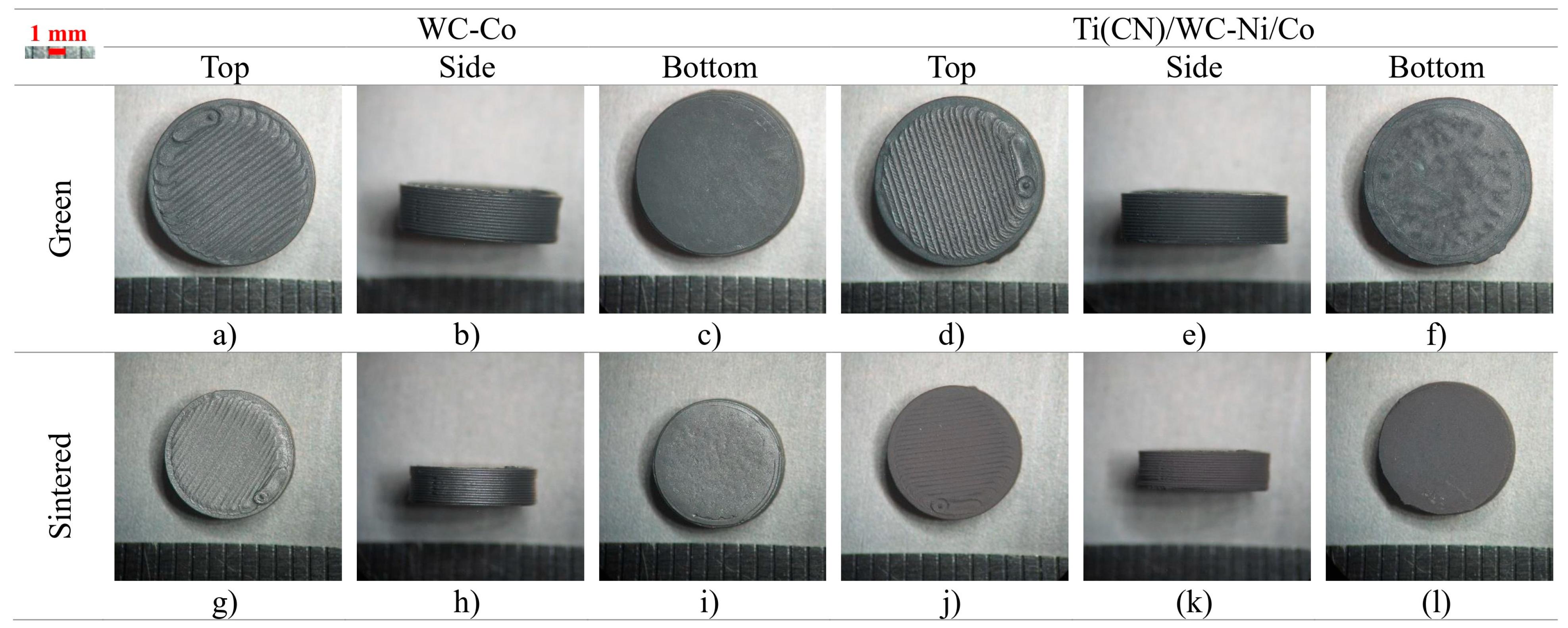
| S1 | Cyl. 2 [D H] | 10.00 × 3.00 | 0.40 | 100 | - | WC and Ti(CN)/WC-Ni/Co |
| S2 | Cyl. 2 [D H] | 10.00 × 5.00 | 0.40 | 100 | - | WC and Ti(CN)/WC-Ni/Co |
| S3 | Cyl. 2 [D H] | 10.00 × 5.00 | 0.25 | 100 | - | WC + Co |
| S4 | Cyl. 2 [D H] | 20.00 × 10.00 | 0.40 | 100 | - | WC + Co |
| S5 | Cyl. 2 [D H] | 20.00 × 10.00 | 0.40 | 100 | - | WC + Co |
| S6 | Cyl. 2 [D H] | 20.00 × 10.00 | 0.40 | 30 (honeycomb) | - | WC + Co |
| S7 | Cyl. 2 [D H] | 20.00 × 10.00 | 0.40 | 100 | 4.00 (4 holes) | WC + Co |
| S8 | Cyl. 2 [D H] | 20.00 × 10.00 | 0.40 | 100 | 8.00 (1 hole) | WC + Co |
| S9 | Cyl. 2 [D H] | 20.00 × 10.00 | 0.40 | 0 | 19.20 (thin wall) | WC + Co |
| Cube | Average Height of Selected Area—Sa (µm) | Maximum Height of Selected Area—Sz (µm) | |||||
|---|---|---|---|---|---|---|---|
| Top | Side | Bottom | Top | Side | Bottom | ||
| Green | C1 (0.40) | 5.71 | 19.69 | 0.90 | 171.64 | 146.19 | 34.58 |
| C2 (0.25) | 3.69 | 9.49 | 0.70 | 158.18 | 107.36 | 9.42 | |
| Sintered | C1 (0.40) | 4.42 | 14.86 | 2.37 | 152.15 | 106.78 | 36.17 |
| C2 (0.25) | 2.61 | 7.77 | 6.13 | 104.84 | 65.17 | 130.88 | |
| Circle Diameter (mm) | ||||||||||||||||||
|---|---|---|---|---|---|---|---|---|---|---|---|---|---|---|---|---|---|---|
| #1 | #2 | #3 | #4 | #5 | #6 | #7 | #8 | |||||||||||
| Nominal (Green) | 4.00 | 3.50 | 3.00 | 2.50 | 2.00 | 1.50 | 1.00 | 0.50 | ||||||||||
| Green | Vertical Holes | 0.40 | 3.96 | ±0.02 | 3.49 | ±0.03 | 2.96 | ±0.03 | 2.41 | ±0.02 | 1.90 | ±0.02 | 1.35 | ±0.01 | 0.79 | ±0.01 | blocked | blocked |
| 0.25 | 4.01 | ±0.02 | 3.49 | ±0.02 | 2.95 | ±0.02 | 2.45 | ±0.02 | 1.94 | ±0.02 | 1.42 | ±0.03 | 0.85 | ±0.03 | blocked | blocked | ||
| Horizontal Holes | 0.40 | 3.04 | ±0.17 | 2.60 | ±0.33 | 2.12 | ±0.24 | 1.57 | ±0.17 | 1.07 | ±0.15 | 0.50 | ±0.13 | |||||
| 0.25 | 2.84 | ±0.23 | 2.49 | ±0.17 | 2.09 | ±0.99 | 1.54 | ±0.14 | 1.11 | ±0.14 | 0.41 | ±0.09 | ||||||
| Sintered | Vertical Holes | 0.40 | 3.08 | ±0.02 | 2.75 | ±0.03 | 2.34 | ±0.04 | 1.92 | ±0.03 | 1.49 | ±0.02 | 1.07 | ±0.02 | 0.62 | ±0.02 | blocked | blocked |
| 0.25 | 3.13 | ±0.02 | 2.80 | ±0.04 | 2.37 | ±0.04 | 1.98 | ±0.03 | 1.57 | ±0.03 | 1.15 | ±0.04 | 0.67 | ±0.04 | blocked | blocked | ||
| Horizontal Holes | 0.40 | 2.40 | ±0.14 | 1.70 | ±0.17 | 1.64 | ±0.21 | 1.19 | ±0.14 | 0.82 | ±0.10 | 0.40 | ±0.12 | |||||
| 0.25 | 2.01 | ±0.16 | 1.96 | ±0.07 | 1.62 | ±0.08 | 1.22 | ±0.05 | 0.80 | ±0.05 | 0.33 | ±0.03 | ||||||
| [mm] | WC-Co | Ti(CN)/WC-Ni/Co | ||
|---|---|---|---|---|
| Diameter | Height | Diameter | Height | |
| Nominal | 10.00 | 3.00 | 10.00 | 3.00 |
| Green | 10.00 ± 0.05 | 3.02 ± 0.01 | 10.06 ± 0.04 | 3.06 ± 0.01 |
| Sintered | 7.83 ± 0.10 | 2.38 ± 0.03 | 8.08 ± 0.03 | 2.48 ± 0.04 |
| Shrinkage | 21.7% | 21.2% | 19.7% | 19.0% |
| [mm] | WC-Co | Ti(CN)/WC-Ni/Co | ||
|---|---|---|---|---|
| Diameter | Height | Diameter | Height | |
| Nominal | 10.00 | 5.00 | 10.00 | 5.00 |
| Green | 9.95 ± 0.02 | 4.99 ± 0.11 | 10.17 ± 0.01 | 5.13 ± 0.04 |
| Sintered | 7.62 ± 0.04 (+0.37 max.) | 3.95 ± 0.10 (+1.48 max.) | 8.13 ± 0.10 (+0.10 max.) | 4.27 ± 0.06 (+1.57 max.) |
| Shrinkage | 23.4% | 20.8% | 20.1% | 16.8% |
| [mm] | Defect | No Defect | ||
|---|---|---|---|---|
| Diameter | Height | Diameter | Height | |
| Nominal | 10.00 | 5.00 | 10.00 | 5.00 |
| Green | 9.91 ± 0.03 | 4.98 ± 0.02 | 9.91 ± 0.03 | 4.98 ± 0.02 |
| Sintered | 7.61 ± 0.10 (+0.62 max.) | 3.88 ± 0.05 (+1.8 max.) | 7.70 ± 0.05 | 3.92 ± 0.02 |
| Shrinkage | 23.2% | 22.1% | 22.3% | 21.3% |
| [mm] | Diameter | Height | Hole Diameter | |
|---|---|---|---|---|
| S4 | Nominal | 20.00 | 3.00 | - |
| Green | 19.96 | 3.06 | - | |
| Sintered | 15.60 | 2.33 (4.37 max.) | - | |
| Shrinkage | 21.8% | 23.9% | - | |
| S5 | Nominal | 20.00 | 10.00 | - |
| Green | 20.06 | 10.15 | - | |
| Sintered | 15.58 (16.24 max.) | 7.99 (9.71 max.) | - | |
| Shrinkage | 22.3% | 21.3% | - | |
| S6 | Nominal | 20.00 | 10.00 | - |
| Green | 19.85 | 10.03 | - | |
| Sintered | 15.68 | 7.55 | - | |
| Shrinkage | 21.0% | 24.7% | - | |
| S7 | Nominal | 20.00 | 10.00 | 4.00/4.00/4.00/4.00 |
| Green | 19.96 | 10.07 | 3.87/3.81/3.82/3.84 | |
| Sintered | 16.02 | 8.26 | 2.89/2.93/2.91/2.92 | |
| Shrinkage | 19.7% | 18.0% | 25.0% | |
| S8 | Nominal | 20.00 | 10.00 | 8.00 |
| Green | 19.94 | 10.02 | 7.8 | |
| Sintered | 15.6 | 7.9 | 5.8 | |
| Shrinkage | 21.8% | 21.2% | 25.6% | |
| S9 | Nominal | 20.00 | 10.00 | 19.20 |
| Green | 19.86 | 9.96 | 19.04 | |
| Sintered | Colapse | |||
| Shrinkage | ||||
| WC-Co | Ti(CN)/WC-Ni/Co | |||
|---|---|---|---|---|
| Pressing-and-Sintering | MEX | Pressing-and-Sintering | MEX | |
| Hardness [HV1/15] | 1702 ± 28 | 1649 ± 24 | 1872 ± 23 | 1265 ± 60 |
Disclaimer/Publisher’s Note: The statements, opinions and data contained in all publications are solely those of the individual author(s) and contributor(s) and not of MDPI and/or the editor(s). MDPI and/or the editor(s) disclaim responsibility for any injury to people or property resulting from any ideas, methods, instructions or products referred to in the content. |
© 2023 by the authors. Licensee MDPI, Basel, Switzerland. This article is an open access article distributed under the terms and conditions of the Creative Commons Attribution (CC BY) license (https://creativecommons.org/licenses/by/4.0/).
Share and Cite
Oliveira, G.; Senos, A.; Fernandes, C.; Figueiredo, D.; Vieira, T. Material Extrusion to Manufacture Carbide-Based Advanced Cutting Tools. Materials 2023, 16, 6902. https://doi.org/10.3390/ma16216902
Oliveira G, Senos A, Fernandes C, Figueiredo D, Vieira T. Material Extrusion to Manufacture Carbide-Based Advanced Cutting Tools. Materials. 2023; 16(21):6902. https://doi.org/10.3390/ma16216902
Chicago/Turabian StyleOliveira, Gonçalo, Ana Senos, Cristina Fernandes, Daniel Figueiredo, and Teresa Vieira. 2023. "Material Extrusion to Manufacture Carbide-Based Advanced Cutting Tools" Materials 16, no. 21: 6902. https://doi.org/10.3390/ma16216902