
The Effect of Selective Laser Melting Fabrication Parameters on the Tensile Strength of an Aged New Maraging Steel Alloy with 8% Cr, Reduced Ni Content (7%), and No Co or Mo
 , and
, and
Abstract
:1. Introduction
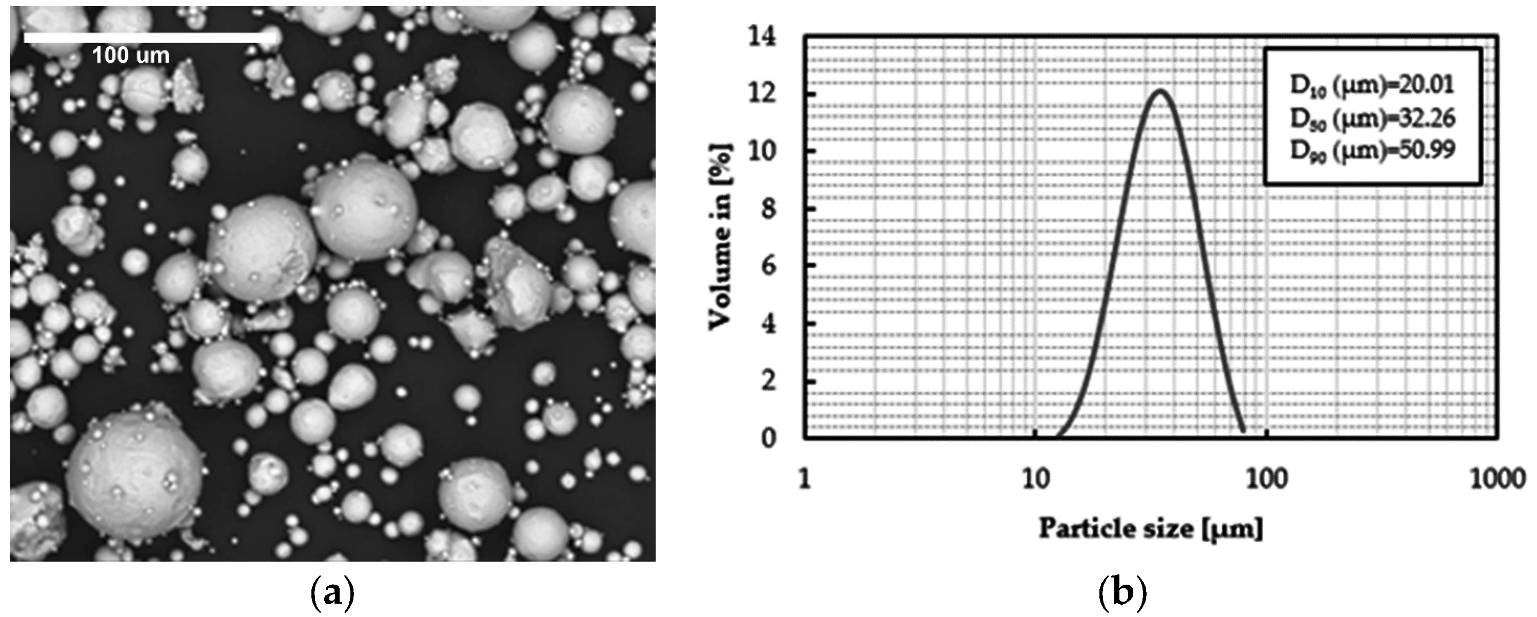
- LeanSi steel is introduced. This new alloy has mechanical properties comparable to those of conventional M300 steels, but with a reduced cost. It was developed by ArcelorMittal and manufactured using the SLM process, with 8% Cr, a reduced Ni content (7%), and without Co or Mo.
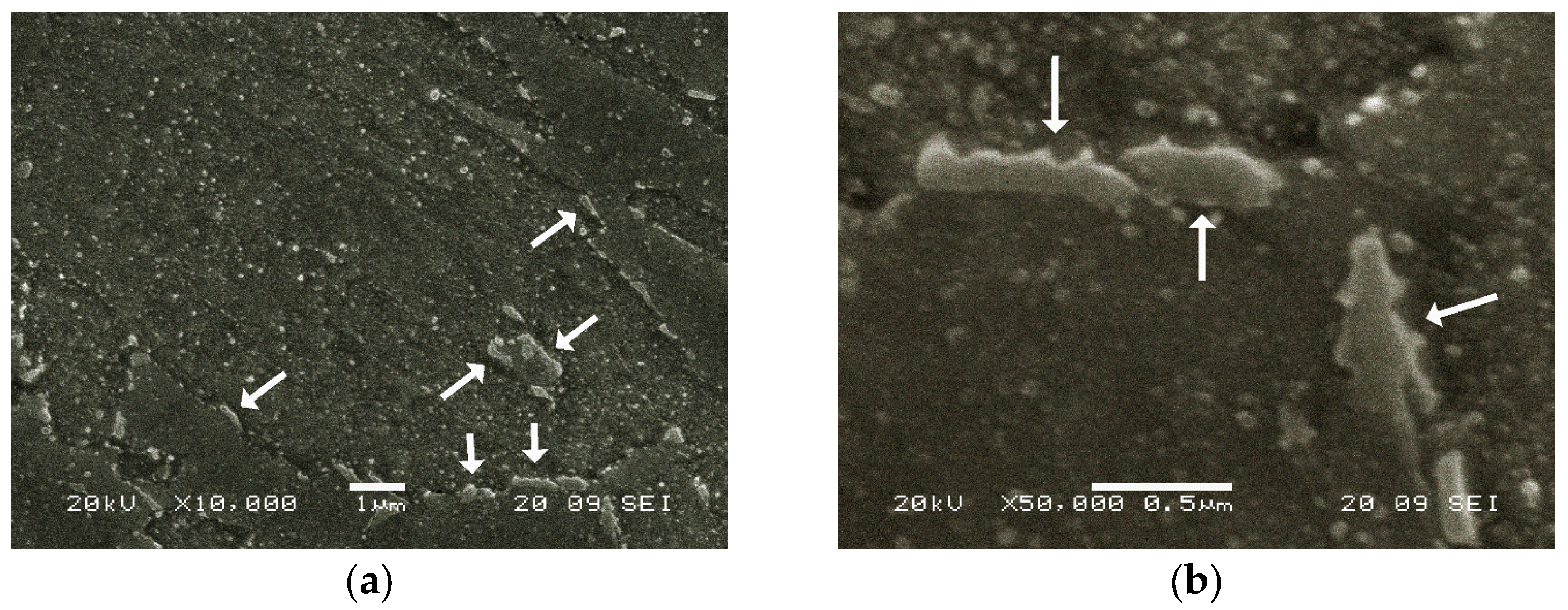
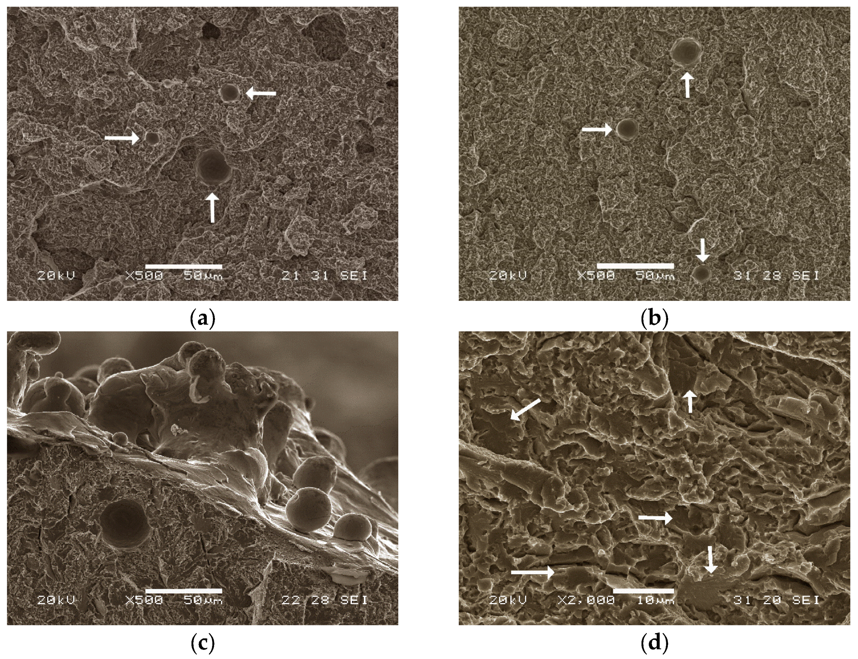
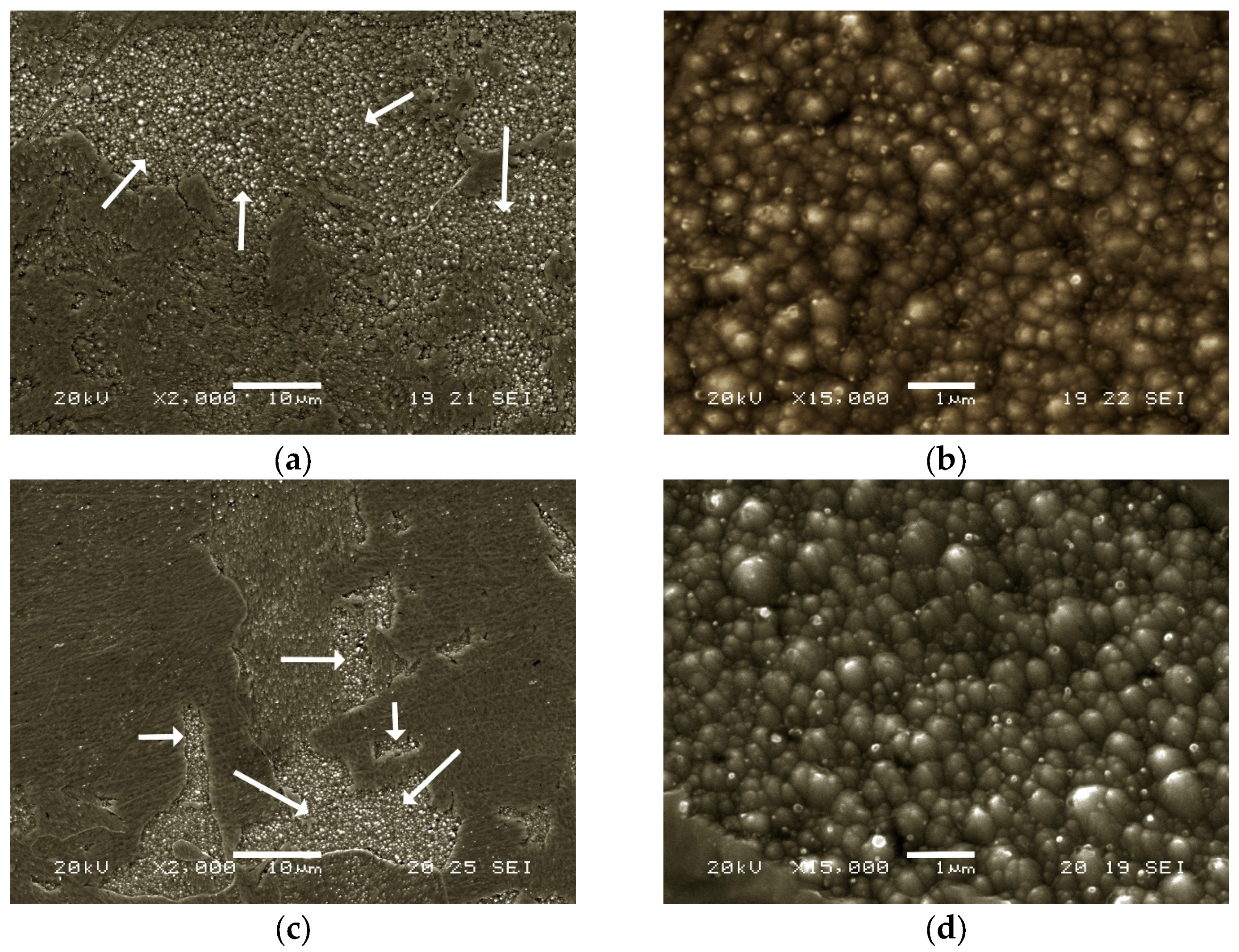
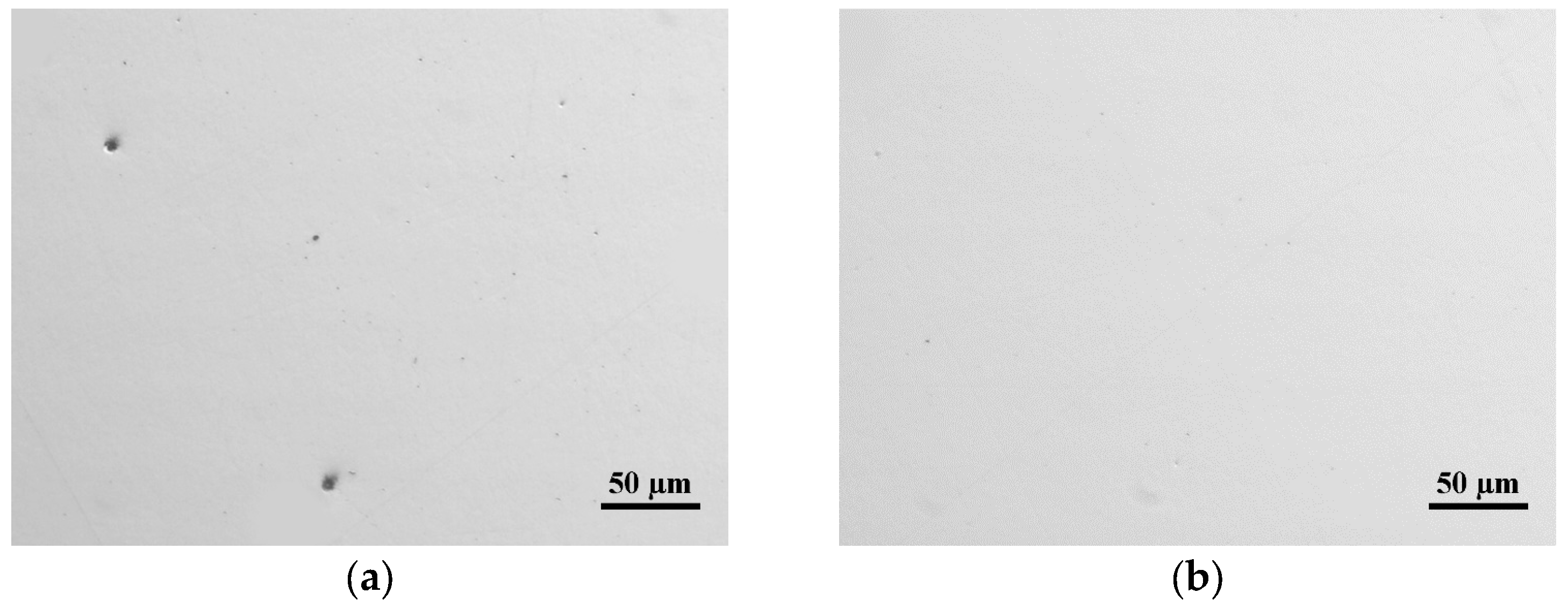
- Bond defects generated during the manufacturing process are analysed.
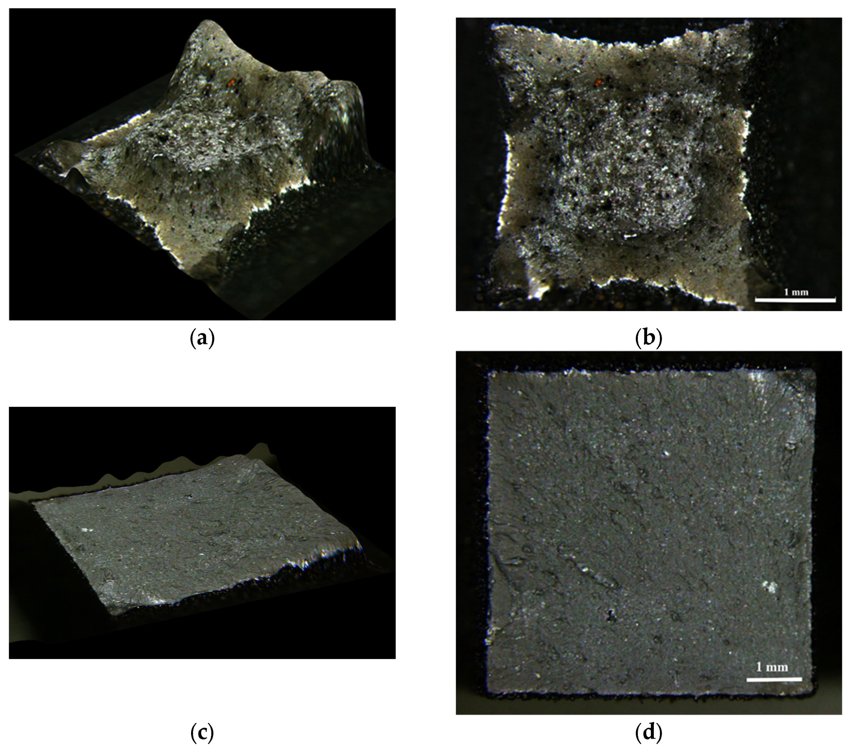
- Experiments are carried out to optimise the fabrication parameters used in the manufacturing process of this alloy, with the aim of producing a defect-free material.
2. Materials and Methods
3. Results and Discussion
4. Conclusions
Author Contributions
Funding
Institutional Review Board Statement
Informed Consent Statement
Data Availability Statement
Conflicts of Interest
References
- Jiang, S.; Wang, H.; Wu, Y.; Liu, X.; Chen, H.; Yao, M.; Gault, B.; Ponge, D.; Raabe, D.; Hirata, A.; et al. Ultrastrong steel via minimal lattice misfit and high-density nanoprecipitation. Nature 2017, 544, 460. [Google Scholar] [CrossRef] [PubMed]
- El-Fawkhry, M.K.; Eissa, M.; Fathy, A.; Mattar, T. Development of maraging steel with retained austenite in martensite matrix. Mater. Today-Proc. 2015, 2, 711–714. [Google Scholar] [CrossRef]
- Kolomy, S.; Sedlak, J.; Zouhar, J.; Slany, M.; Benc, M.; Dobrocky, D.; Barenyi, I.; Majerik, J. Influence of Ageing Temperature on Mechanical Properties and Structure of M300 Maraging Steel Produced by Selective Laser Melting. Materials 2023, 16, 977. [Google Scholar] [CrossRef] [PubMed]
- Wust, P.; Edelmann, A.; Hellmann, R. Areal Surface Roughness Optimization of Maraging Steel Parts Produced by Hybrid Additive Manufacturing. Materials 2020, 13, 418. [Google Scholar] [CrossRef] [PubMed]
- Rosenauer, A.; Brandl, D.; Ressel, G.; Lukas, S.; Monschein, S.; Stockinger, M.; Schnitzer, R. Influence of delta ferrite on the impact toughness of a PH 13-8 Mo maraging steel. Mater. Sci. Eng. A-Struct. Mater. Prop. Microstruct. Process. 2022, 856, 144024. [Google Scholar] [CrossRef]
- Mahmoudi, A.; Ghavidel, M.R.Z.; Nedjad, S.H.; Heidarzadeh, A.; Ahmadabadi, M.N. Ageing behavior and mechanical properties of maraging steels in the presence of submicrocrystalline Laves phase particles. Mater. Charact. 2011, 62, 976–981. [Google Scholar] [CrossRef]
- Ahmadkhaniha, D.; Moller, H.; Zanella, C. Studying the Microstructural Effect of Selective Laser Melting and Electropolishing on the Performance of Maraging Steel. J. Mater. Eng. Perform. 2021, 30, 6588–6605. [Google Scholar] [CrossRef]
- Liu, P.; Stigenberg, A.H.; Nilsson, J.O. Quasi-crystalline and crystalline precipitation during isothermal tempering in a 12Cr-9Ni-4Mo maraging stainless-steel. Acta Metall. Et Mater. 1995, 43, 2881–2890. [Google Scholar] [CrossRef]
- Huang, C.Y.; Yen, H.W. HRTEM investigations on nano precipitates in Custom 475 maraging stainless steel. Mater. Charact. 2021, 178, 111216. [Google Scholar] [CrossRef]
- Wan, J.Q.; Ruan, H.H.; Ding, Z.Y.; Kong, L.B. A novel maraging stainless steel ultra-high-strengthened by multi-nanoprecipitations. Scr. Mater. 2023, 226, 115224. [Google Scholar] [CrossRef]
- Wan, S.H.; Li, H.; Tieu, K.; Xue, Q.; Zhu, H.T. Mechanical and tribological assessments of high-vanadium high-speed steel by the conventional powder metallurgy process. Int. J. Adv. Manuf. Technol. 2019, 103, 943–955. [Google Scholar] [CrossRef]
- Song, J.; Tang, Q.; Feng, Q.X.; Ma, S.; Setchi, R.; Liu, Y.; Han, Q.Q.; Fan, X.J.; Zhang, M.X. Effect of heat treatment on microstructure and mechanical behaviours of 18Ni-300 maraging steel manufactured by selective laser melting. Opt. Laser Technol. 2019, 120, 105725. [Google Scholar] [CrossRef]
- Chales, R.; Martins Cardoso, A.d.S.; Pires Garcia, P.S.; da Igreja, H.R.; de Almeida, B.B.; Noris, L.F.; Pardal, J.M.; Maior Tavares, S.S.; da Silva, M.M. Behavior of constitutive models from slow strain rate test of maraging 300 and 350 steels performed in several environmental conditions. Int. J. Fract. 2022, 234, 159–175. [Google Scholar] [CrossRef]
- Lian, Y.; Ma, M.; Zhang, J.; Huang, J.; Gao, W.; Zhang, Z.; Zhao, C. Influence of Austenitizing Temperature on the Microstructure and Mechanical Properties of an Fe-Cr-Ni-Mo-Ti Maraging Stainless Steel. J. Mater. Eng. Perform. 2019, 28, 5466–5475. [Google Scholar] [CrossRef]
- Simm, T.H.; Sun, L.; Galvin, D.R.; Hill, P.; Rawson, M.; Birosca, S.; Gilbert, E.P.; Bhadeshia, H.; Perkins, K. The Effect of a Two-Stage Heat-Treatment on the Microstructural and Mechanical Properties of a Maraging Steel. Materials 2017, 10, 1346. [Google Scholar] [CrossRef] [PubMed]
- Makhneva, T.M.; Sukhikh, A.A.; Dement’ev, V.B. Inverse Martensitic alpha -> gamma Transformation in Nanostructured Maraging Steels. Met. Sci. Heat Treat. 2017, 59, 473–478. [Google Scholar] [CrossRef]
- Ancey-Rocchi, S.; Vidal, V.; Poulain, T.; Billot, T.; Bechet, D.; Binot, N.; Huleux, V.; Dehmas, M.; Delagnes, D. Influence of Austenitization Parameters on the Precipitation Sequence and the Chemical Homogenization of Austenite in a High-Performance Fe-Ni-Cr-Al-Ti-Mo Stainless Maraging Steel. Metall. Mater. Trans. A-Phys. Metall. Mater. Sci. 2021, 52, 4623–4635. [Google Scholar] [CrossRef]
- Li, X.D.; Yin, Z.D. Reverted austenite during ageing in 18Ni(350) maraging-steel. Mater. Lett. 1995, 24, 239–242. [Google Scholar] [CrossRef]
- Dhinakar, A.; Li, B.E.; Chang, Y.C.; Chiu, K.C.; Chen, J.K. Air Permeability of Maraging Steel Cellular Parts Made by Selective Laser Melting. Materials 2021, 14, 3118. [Google Scholar] [CrossRef] [PubMed]
- Bai, Y.; Zhao, C.; Zhang, J.; Wang, H. Abnormal thermal expansion behaviour and phase transition of laser powder bed fusion maraging steel with different thermal histories during continuous heating. Addit. Manuf. 2022, 53, 102712. [Google Scholar] [CrossRef]
- Zhang, C.; Wang, C.; Wang, A.; Zheng, C.; Liu, Z.; Liang, J.; Su, J.; Ge, Q. Effect of Ageing on Transformation Behavior of Reverted Austenite and Toughness in Co-Free Maraging Stainless Steel. J. Mater. Eng. Perform. 2022, 31, 9850–9863. [Google Scholar] [CrossRef]
- Khan, H.M.; Ozer, G.; Yilmaz, M.S.; Tarakci, G. Improvement of Corrosion Resistance of Maraging Steel Manufactured by Selective Laser Melting Through Intercritical Heat Treatment. Corrosion 2022, 78, 239–248. [Google Scholar] [CrossRef]
- Conde, F.F.; Escobar, J.D.; Oliveira, J.P.; Jardini, A.L.; Bose Filho, W.W.; Avila, J.A. Austenite reversion kinetics and stability during tempering of an additively manufactured maraging 300 steel. Addit. Manuf. 2019, 29, 100804. [Google Scholar] [CrossRef]
- Lima Filho, V.X.; Barros, I.F.; Gomes de Abreu, H.F. Influence of Solution Annealing on Microstructure and Mechanical Properties of Maraging 300 Steel. Mater. Res. Ibero-Am. J. Mater. 2017, 20, 10–14. [Google Scholar] [CrossRef]
- Pardal, J.M.; Tavares, S.S.M.; Fonseca, M.P.C.; da Silva, M.R.; Neto, J.M.; Abreu, H.F.G. Influence of temperature and ageing time on hardness and magnetic properties of the maraging steel grade 300. J. Mater. Sci. 2007, 42, 2276–2281. [Google Scholar] [CrossRef]
- Tavares, S.S.M.; Pardal, J.M.; Martins, T.R.D.; Schmitt, V.M.; Szlejf, J.F.V. Influence of Austenitizing on the Mechanical Properties of Maraging 300 and Sae 4340 Steels—Comparative Study. Mater. Res. Ibero-Am. J. Mater. 2017, 20, 39–46. [Google Scholar] [CrossRef]
- Yin, S.; Chen, C.; Yan, X.; Feng, X.; Jenkins, R.; O’Reilly, P.; Liu, M.; Li, H.; Lupoi, R. The influence of ageing temperature and ageing time on the mechanical and tribological properties of selective laser melted maraging 18Ni-300 steel. Addit. Manuf. 2018, 22, 592–600. [Google Scholar] [CrossRef]
- Huang, G.; Wei, K.; Deng, J.; Zeng, X. High power laser powder bed fusion of 18Ni300 maraging steel: Processing optimization, microstructure and mechanical properties. Mater. Sci. Eng. A-Struct. Mater. Prop. Microstruct. Process. 2022, 856, 143983. [Google Scholar] [CrossRef]
- Dehgahi, S.; Sanjari, M.; Ghoncheh, M.H.; Amirkhiz, B.S.; Mohammadi, M. Concurrent improvement of strength and ductility in heat-treated C300 maraging steels produced by laser powder bed fusion technique. Addit. Manuf. 2021, 39, 101847. [Google Scholar] [CrossRef]
- Ma, Y.; Gao, Y.; Zhao, L.; Li, D.; Men, Z. Optimization of Process Parameters and Analysis of Microstructure and Properties of 18Ni300 by Selective Laser Melting. Materials 2022, 15, 4757. [Google Scholar] [CrossRef] [PubMed]
- West, C.; Wang, X. Modeling of selective laser sintering/selective laser melting. In Proceedings of the Conference on Laser 3D Manufacturing IV, San Francisco, CA, USA, 30 January–2 February 2017. [Google Scholar]
- Gor, M.; Soni, H.; Rajput, G.S.; Sahlot, P. Experimental investigation of mechanical properties for wrought and selective laser melting additively manufactured SS316L and MS300. Mater. Today-Proc. 2022, 62, 7215–7219. [Google Scholar] [CrossRef]
- Tan, C.L.; Zhou, K.S.; Ma, W.Y.; Zhang, P.P.; Liu, M.; Kuang, T.C. Microstructural evolution, nanoprecipitation behavior and mechanical properties of selective laser melted high-performance grade 300 maraging steel. Mater. Des. 2017, 134, 23–34. [Google Scholar] [CrossRef]
- Bae, K.C.; Kim, D.; Kim, Y.H.; Oak, J.J.; Lee, H.; Lee, W.; Park, Y.H. Effect of heat treatment, building direction, and sliding velocity on wear behavior of selectively laser-melted maraging 18Ni-300 steel against bearing steel. Wear 2021, 482, 203962. [Google Scholar] [CrossRef]
- Mumtaz, K.; Hopkinson, N. Top surface and side roughness of Inconel 625 parts processed using selective laser melting. Rapid Prototyp. J. 2009, 15, 96–103. [Google Scholar] [CrossRef]
- Angelastro, A.; Campanelli, S.L. An integrated analytical model for the forecasting of the molten pool dimensions in Selective Laser Melting. Laser Phys. 2022, 32, 026001. [Google Scholar] [CrossRef]
- Kim, D.; Kim, T.; Ha, K.; Oak, J.-J.; Jeon, J.B.; Park, Y.; Lee, W. Effect of Heat Treatment Condition on Microstructural and Mechanical Anisotropies of Selective Laser Melted Maraging 18Ni-300 Steel. Metals 2020, 10, 410. [Google Scholar] [CrossRef]
- Bae, K.; Kim, D.; Lee, W.; Park, Y. Wear Behavior of Conventionally and Directly Aged Maraging 18Ni-300 Steel Produced by Laser Powder Bed Fusion. Materials 2021, 14, 2588. [Google Scholar] [CrossRef] [PubMed]
- Habassi, F.; Houria, M.; Barka, N.; Jahazi, M. Influence of post-treatment on microstructure and mechanical properties of additively manufactured C300 maraging steel. Mater. Charact. 2023, 202, 112980. [Google Scholar] [CrossRef]
- Wang, J.C.; Zhu, R.; Liu, Y.J.; Zhang, L.C. Understanding melt pool characteristics in laser powder bed fusion: An overview of single- and multi-track melt pools for process optimization. Adv. Powder Mater. 2023, 2, 100137. [Google Scholar] [CrossRef]
- Mugwagwa, L.; Yadroitsev, I.; Matope, S. Effect of Process Parameters on Residual Stresses, Distortions, and Porosity in Selective Laser Melting of Maraging Steel 300. Metals 2019, 9, 1042. [Google Scholar] [CrossRef]
- Becker, T.H.; Dimitrov, D. The achievable mechanical properties of SLM produced Maraging Steel 300 components. Rapid Prototyp. J. 2016, 22, 487–494. [Google Scholar] [CrossRef]
- Santos, L.M.S.; Ferreira, J.A.M.; Jesus, J.S.; Costa, J.M.; Capela, C. Fatigue behaviour of selective laser melting steel components. Theor. Appl. Fract. Mech. 2016, 85, 9–15. [Google Scholar] [CrossRef]
- Zhu, Z.Y.; Liu, Y.L.; Gou, G.Q.; Gao, W.; Chen, J. Effect of heat input on interfacial characterization of the butter joint of hot-rolling CP-Ti/Q235 bimetallic sheets by Laser plus CMT. Sci. Rep. 2021, 11, 10020. [Google Scholar] [CrossRef]
- Morgan, R.; Sutcliffe, C.J.; O’Neill, W. Density analysis of direct metal laser re-melted 316L stainless steel cubic primitives. J. Mater. Sci. 2004, 39, 1195–1205. [Google Scholar] [CrossRef]
- Guo, Q.X.; Wang, Y.S.; Lin, J.H. Effect of additive and subtractive hybrid manufacturing process on the surface quality of 18Ni300 maraging steel. Mater. Res. Express 2023, 10, 056501. [Google Scholar] [CrossRef]
- Kruth, J.P.; Froyen, L.; Van Vaerenbergh, J.; Mercelis, P.; Rombouts, M.; Lauwers, B. Selective laser melting of iron-based powder. J. Mater. Process. Technol. 2004, 149, 616–622. [Google Scholar] [CrossRef]
- Gusarov, A.V.; Yadroitsev, I.; Bertrand, P.; Smurov, I. Heat transfer modelling and stability analysis of selective laser melting. Appl. Surf. Sci. 2007, 254, 975–979. [Google Scholar] [CrossRef]
- Das, S. Physical aspects of process control in selective laser sintering of metals. Adv. Eng. Mater. 2003, 5, 701–711. [Google Scholar] [CrossRef]
- Law, W.K.; Wu, Z.Y.; Song, C.H.; Wang, H.L.; Wong, K.C.; Lim, C.S.; Sun, Z.Z. Optimization of Selective Laser Melting Process Parameters Via Taguchi’s Methods and Gray Relational Analysis for 3D Printing of 18Ni-300 Maraging Steel. Steel Res. Int. 2023, 94, 2200203. [Google Scholar] [CrossRef]
- Mico-Vicent, B.; Perales, E.; Huraibat, K.; Martinez-Verdu, F.M.; Viqueira, V. Maximization of FDM-3D-Objects Gonio-Appearance Effects Using PLA and ABS Filaments and Combining Several Printing Parameters: “A Case Study”. Materials 2019, 12, 1423. [Google Scholar] [CrossRef]
- Gallardo-Sanchez, M.A.; Diaz-Vidal, T.; Navarro-Hermosillo, A.B.; Figueroa-Ochoa, E.B.; Casillas, R.R.; Hernandez, J.A.; Rosales-Rivera, L.C.; Martinez, J.; Enriquez, S.G.; Macias-Balleza, E.R. Optimization of the Obtaining of Cellulose Nanocrystals from Agave tequilana Weber Var. Azul Bagasse by Acid Hydrolysis. Nanomaterials 2021, 11, 520. [Google Scholar] [CrossRef] [PubMed]
- Mathivanan, N.R.; Babu, N.S.M.; Kumar, K.V. Empirical study on twisting force using Taguchi doe technique during drilling of hybrid FRP laminate. Rev. Des Compos. Et Des Mater. Av.-J. Compos. Adv. Mater. 2018, 28, 277–288. [Google Scholar] [CrossRef]
- Maskovic, M.; Jancic-Stojanovic, B.; Malenovic, A.; Ivanovic, D.; Medenica, M. Assessment of Liquid Chromatographic Method Robustness by Use of Plackett-Burman Design. Acta Chromatogr. 2010, 22, 281–296. [Google Scholar] [CrossRef]
- Srinivasan, P.M.; Dharmakkan, N.; Vishnu, M.D.S.; Prasath, H.; Gogul, R. Thermal conductivity analysis of Al2O3/water-ethylene glycol nanofluid by using factorial design of experiments in a natural convection heat transfer apparatus. Hem. Ind. 2021, 75, 341–352. [Google Scholar] [CrossRef]
- Nassif, N.; Zeiada, W.; Al-Khateeb, G.; Haridy, S.; Altoubat, S. Assessment of Punching Shear Strength of Fiber-reinforced Concrete Flat Slabs Using Factorial Design of Experiments. Jordan J. Civ. Eng. 2022, 16, 139–154. [Google Scholar]
- Mouelhi, M.; Marzouk, I.; Hamrouni, B. Optimization studies for water defluoridation by adsorption: Application of a design of experiments. Desalination Water Treat. 2016, 57, 9889–9899. [Google Scholar] [CrossRef]
- Kumar, S.; Bablu, M.; Janghela, S.; Misra, M.K.; Mishra, R.; Ranjan, A.; Prasad, N.E. Factorial design, processing, characterization and microstructure analysis of PIP-based C/SiC composites. Bull. Mater. Sci. 2018, 41, 17. [Google Scholar] [CrossRef]
- Nurulhuda, A.; Hafrzzal, Y.; Izzuddin, M.Z.M.; Sulawati, M.R.N.; Rafidah, A.; Suhaila, Y.; Fauziah, A.R. Analysis on Flexural Strength of A36 Mild Steel by Design of Experiment (DOE). In Proceedings of the International Research and Innovation Summit (IRIS), Melaka, Malaysia, 6–7 May 2017. [Google Scholar]
- UNE-EN-ISO 6892-1:2020; Metallic Materials—Tensile Testing—Part 1: Method of Test at Room Temperature. ISO: Geneva, Switzerland, 2020.
- Suryawanshi, J.; Prashanth, K.G.; Ramamurty, U. Tensile, fracture, and fatigue crack growth properties of a 3D printed maraging steel through selective laser melting. J. Alloys Compd. 2017, 725, 355–364. [Google Scholar] [CrossRef]
- Demir, A.G.; Previtali, B. Investigation of remelting and preheating in SLM of 18Ni300 maraging steel as corrective and preventive measures for porosity reduction. Int. J. Adv. Manuf. Technol. 2017, 93, 2697–2709. [Google Scholar] [CrossRef]
- Yan, X.C.; Huang, C.J.; Chen, C.Y.; Bolot, R.; Dembinski, L.; Huang, R.Z.; Ma, W.Y.; Liao, H.L.; Liu, M. Additive manufacturing of WC reinforced maraging steel 300 composites by cold spraying and selective laser melting. Surf. Coat. Technol. 2019, 371, 161–171. [Google Scholar] [CrossRef]


| Cr | Ni | Si | Ti | Cu | Fe |
|---|---|---|---|---|---|
| 8 | 7 | 1 | 1 | 1 | Bal. |
| Factors | Levels | ||||
|---|---|---|---|---|---|
| Code | Description of the Factors | Units | Level −1 | Level 0 | Level 1 |
| A | Laser power (LP) | W | 200 | -- | 250 |
| B | Scanning speed (SS) | mm/s | 1000 | -- | 1250 |
| C | Hatch distance (HD) | μm | 80 | 90 | 110 |
| Experiment | A | B | C | Restricted Confusion Pattern |
|---|---|---|---|---|
| 1 | −1 | −1 | −1 | Factor A Factor B Factor C Interaction AB Interaction AC Interaction BC |
| 2 | 1 | −1 | −1 | |
| 3 | −1 | 1 | −1 | |
| 4 | 1 | 1 | −1 | |
| 5 | −1 | −1 | 1 | |
| 6 | 1 | −1 | 1 | |
| 7 | −1 | 1 | 1 | |
| 8 | 1 | 1 | 1 |
| Sample | Rietveld Adjustment | Phase | a (Å) | wt. % |
|---|---|---|---|---|
| Without austenitisation treatment (without AT) | Rwp = 11.8 Chi2 = 1.82 | Ferrite | 2.874 | 100 |
| With austenitisation treatment (whit AT) | Rwp = 11.8 Chi2 = 2.36 | Ferrite | 2.874 | 100 |
| Experiment | Replicate 0 | Replicate 1 | Replicate 2 | Effects | |
|---|---|---|---|---|---|
| 1 | 0.12 | 0.19 | 0.14 | ||
| 2 | 0.06 | 0.07 | 0.06 | ||
| 3 | 0.34 | 0.36 | 0.32 | ||
| 4 | 0.21 | 0.23 | 0.2 | −0.45 | A |
| 5 | 0.19 | 0.16 | 0.17 | 0.52 | B |
| 6 | 0.08 | 0.09 | 0.09 | 0.85 | C |
| 7 | 0.42 | 0.41 | 0.37 | −0.17 | AB |
| 8 | 0.26 | 0.25 | 0.24 | −0.46 | AC |
| 9 | 0.75 | 0.71 | 0.74 | 0.46 | BC |
| 10 | 0.22 | 0.19 | 0.24 | ||
| 11 | 2.24 | 2.26 | 2.23 | ||
| 12 | 0.80 | 0.7 | 0.9 | ||
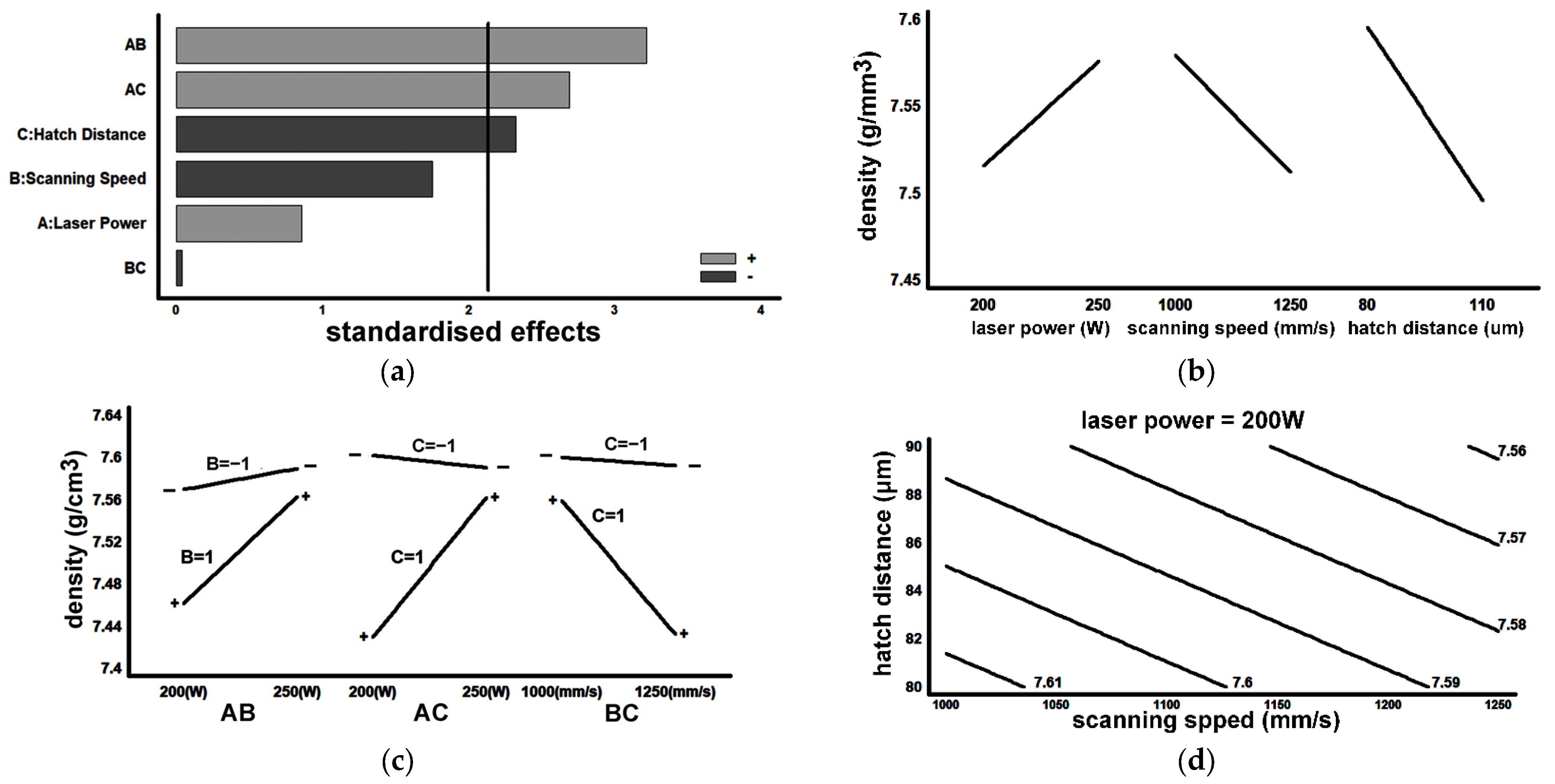
| Experiment | Replicate 0 | Replicate 1 | Replicate 2 | Effects | |
|---|---|---|---|---|---|
| 1 | 7.63 | 7.61 | 7.60 | ||
| 2 | 7.57 | 7.61 | 7.58 | ||
| 3 | 7.59 | 7.59 | 7.57 | ||
| 4 | 7.61 | 7.57 | 7.60 | 0.055 | A |
| 5 | 7.58 | 7.61 | 7.57 | 0.057 | B |
| 6 | 7.59 | 7.59 | 7.59 | 0.097 | C |
| 7 | 7.56 | 7.56 | 7.56 | 0.03 | AB |
| 8 | 7.61 | 7.59 | 7.59 | 0.072 | AC |
| 9 | 7.53 | 7.51 | 7.53 | −0.062 | BC |
| 10 | 7.60 | 7.60 | 7.60 | ||
| 11 | 7.35 | 7.32 | 7.35 | ||
| 12 | 7.53 | 7.55 | 7.50 | ||
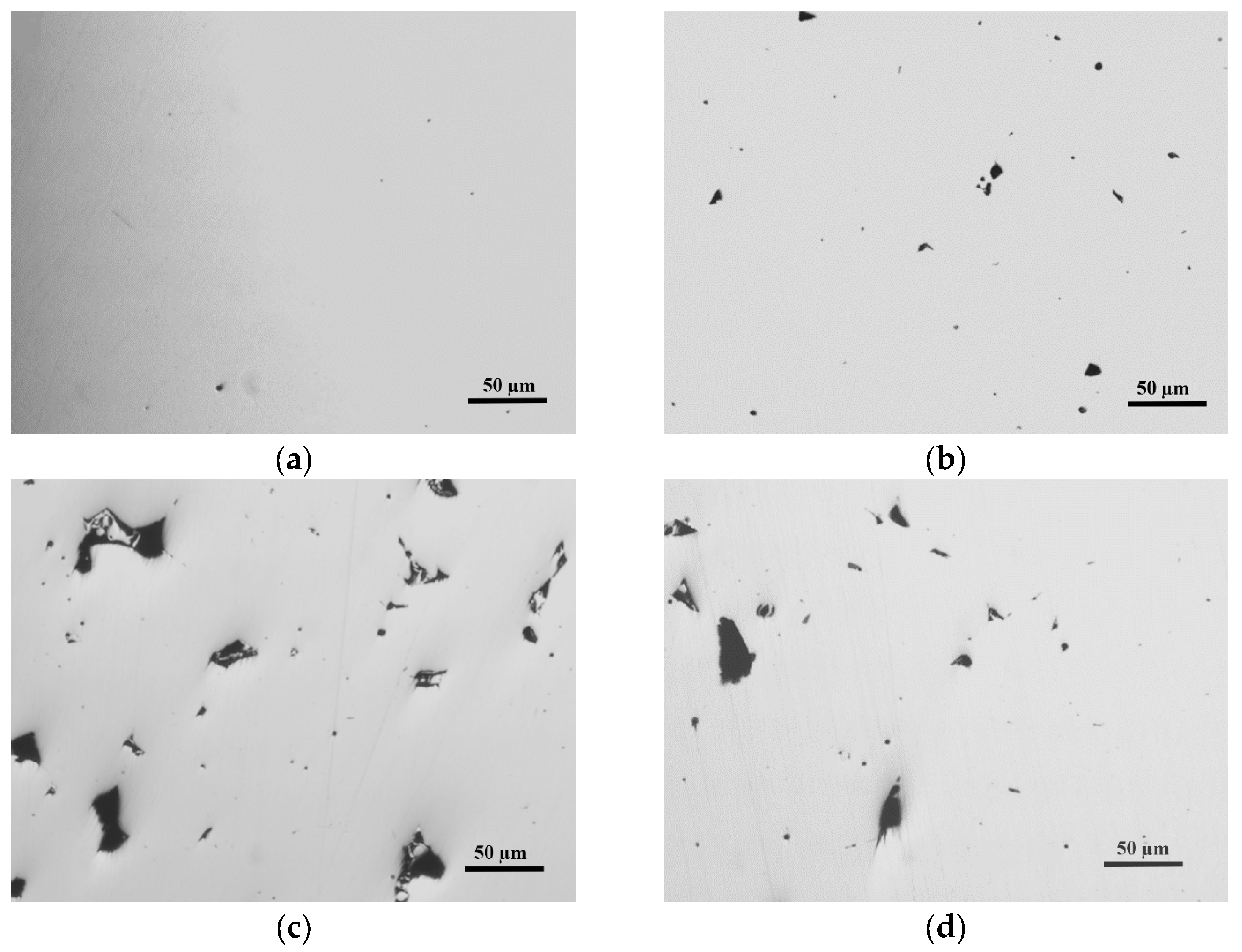
| Laser Power (LP) | State | Porosity (%) |
|---|---|---|
| 200 W | As-printed | 0.16 ± 0.04 |
| 250 W | As-printed | 0.06 ± 0.03 |
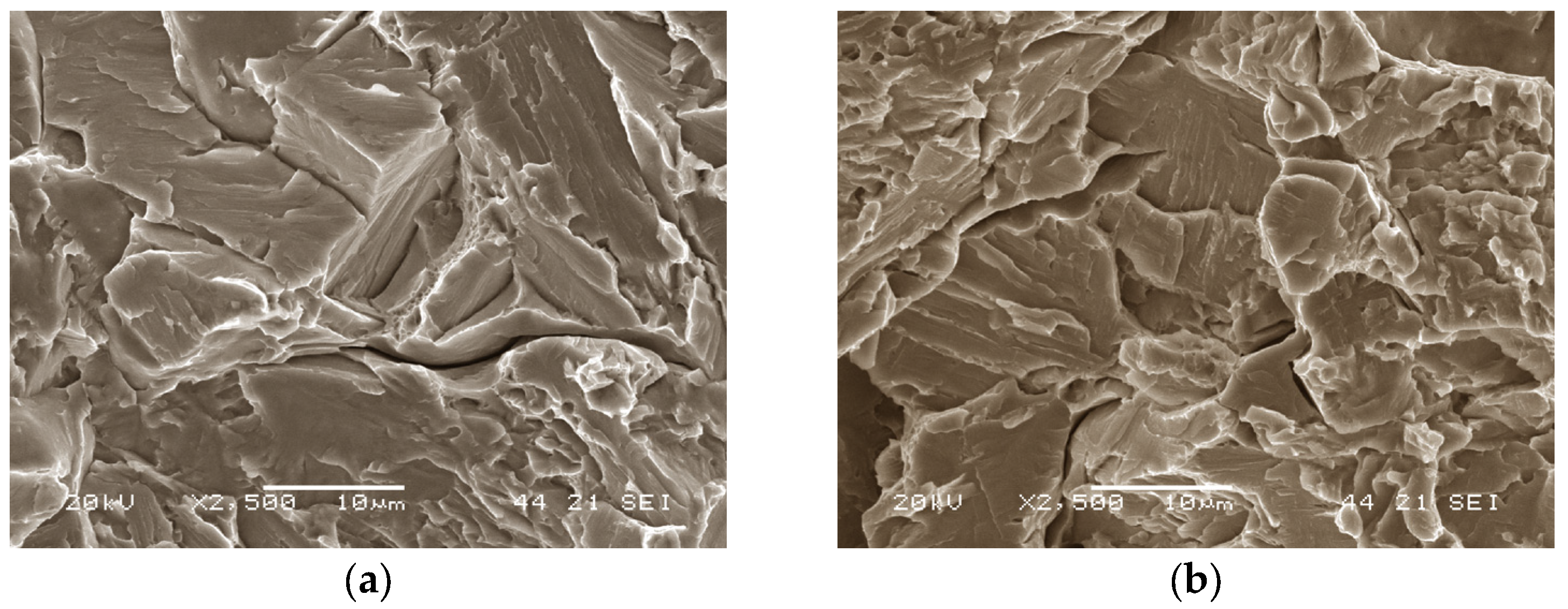
| Laser Power (LP) | State | Ageing | N° Trials | Average (MPa) |
|---|---|---|---|---|
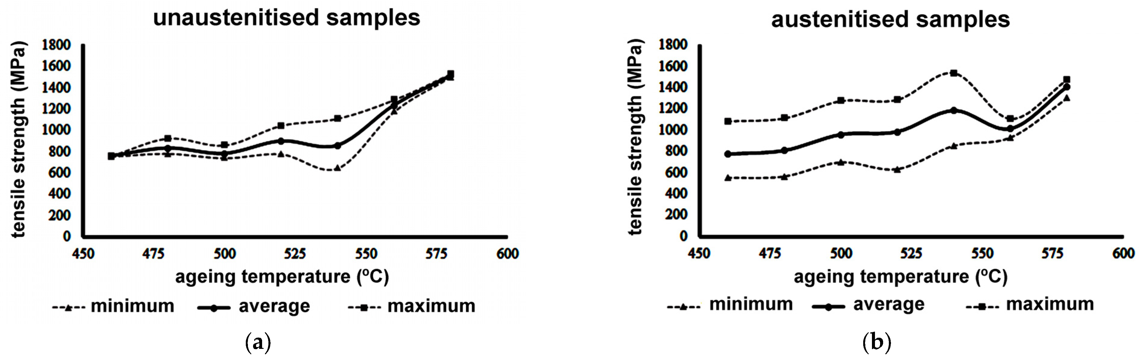
| 200 W | As-printed | 480 °C; 2 h | 3 | 1201 |
| 250 W | As-printed | 480 °C; 2 h | 3 | 1430 |
Disclaimer/Publisher’s Note: The statements, opinions and data contained in all publications are solely those of the individual author(s) and contributor(s) and not of MDPI and/or the editor(s). MDPI and/or the editor(s) disclaim responsibility for any injury to people or property resulting from any ideas, methods, instructions or products referred to in the content. |
© 2023 by the authors. Licensee MDPI, Basel, Switzerland. This article is an open access article distributed under the terms and conditions of the Creative Commons Attribution (CC BY) license (https://creativecommons.org/licenses/by/4.0/).
Share and Cite
Pérez-Gonzalo, I.; González-Pociño, A.; Alvarez-Antolin, F.; del Rio-Fernández, L. The Effect of Selective Laser Melting Fabrication Parameters on the Tensile Strength of an Aged New Maraging Steel Alloy with 8% Cr, Reduced Ni Content (7%), and No Co or Mo. Materials 2023, 16, 7008. https://doi.org/10.3390/ma16217008
Pérez-Gonzalo I, González-Pociño A, Alvarez-Antolin F, del Rio-Fernández L. The Effect of Selective Laser Melting Fabrication Parameters on the Tensile Strength of an Aged New Maraging Steel Alloy with 8% Cr, Reduced Ni Content (7%), and No Co or Mo. Materials. 2023; 16(21):7008. https://doi.org/10.3390/ma16217008
Chicago/Turabian StylePérez-Gonzalo, Inés, Alejandro González-Pociño, Florentino Alvarez-Antolin, and Laura del Rio-Fernández. 2023. "The Effect of Selective Laser Melting Fabrication Parameters on the Tensile Strength of an Aged New Maraging Steel Alloy with 8% Cr, Reduced Ni Content (7%), and No Co or Mo" Materials 16, no. 21: 7008. https://doi.org/10.3390/ma16217008