

Microstructural Characteristics and Material Failure Mechanism of SLM Ti-6Al-4V-Zn Alloy

Abstract
:1. Introduction
2. Materials and Methods
3. Results and Discussion
4. Limitations
5. Conclusions
Author Contributions
Funding
Institutional Review Board Statement
Informed Consent Statement
Data Availability Statement
Acknowledgments
Conflicts of Interest
References
- Jiang, J. A survey of machine learning in additive manufacturing technologies. Int. J. Comput. Integr. Manuf. 2023, 36, 1258–1280. [Google Scholar] [CrossRef]
- Nazir, A.; Gokcekaya, O.; Billah, K.M.M.; Ertugrul, O.; Jiang, J.; Sun, J.; Hussain, S. Multi-material additive manufacturing: A systematic review of design, properties, applications, challenges, and 3D Printing of materials and cellular metamaterials. Mater. Des. 2023, 226, 111661. [Google Scholar] [CrossRef]
- Peters, M.; Kumpfert, J.; Ward, C.H.; Leyens, C. Titanium alloys for aerospace applications. Adv. Eng. Mater. 2003, 5, 419–427. [Google Scholar] [CrossRef]
- Niu, X.; Zhu, S.P.; He, J.C.; Liao, D.; Correia, J.A.; Berto, F.; Wang, Q. Defect tolerant fatigue assessment of AM materials: Size effect and probabilistic prospects. Int. J. Fatigue 2022, 160, 106884. [Google Scholar] [CrossRef]
- Fang, J.X.; Wang, J.X.; Wang, Y.J.; He, H.T.; Zhang, D.B.; Cao, Y. Microstructure evolution and deformation behavior during stretching of a compositionally inhomogeneous TWIP-TRIP cantor-like alloy by laser powder deposition. Mater. Sci. Eng. A 2022, 847, 143319. [Google Scholar] [CrossRef]
- Nandhakumar, R.; Venkatesan, K. A process parameters review on Selective laser melting-based additive manufacturing of Single and Multi-Material: Microstructure, Properties, and machinability aspects. Mater. Today Commun. 2023, 35, 105538. [Google Scholar] [CrossRef]
- Yap, C.Y.; Chua, C.K.; Dong, Z.L.; Liu, Z.H.; Zhang, D.Q.; Loh, L.E.; Sing, S.L. Review of selective laser melting: Materials and applications. Appl. Phys. Rev. 2015, 2, 041101. [Google Scholar] [CrossRef]
- Peng, J.; Li, J.; Liu, B.; Wang, J.; Chen, H.; Feng, H.; Zeng, X.; Duan, H.; Cao, Y.; He, J. Formation process and mechanical properties in selective laser melted multi-principal-element alloys. J. Mater. Sci. Technol. 2023, 133, 12–22. [Google Scholar] [CrossRef]
- Liu, S.; Shin, Y.C. Additive manufacturing of Ti6Al4V alloy: A review. Mater. Des. 2019, 164, 107552. [Google Scholar] [CrossRef]
- Wang, Z.; Zhou, W.; Luo, K.; Lu, H.; Lu, J. Strengthening mechanism in thermomechanical fatigue properties of Ti6Al4V titanium alloy by laser shock peening. Int. J. Fatigue 2023, 172, 107631. [Google Scholar] [CrossRef]
- Zochowski, P.; Bajkowski, M.; Grygoruk, R.; Magier, M.; Burian, W.; Pyka, D.; Jamroziak, M.B.K. Ballistic impact resistance of bulletproof vest inserts containing printed titanium structures. Metals 2021, 11, 225. [Google Scholar] [CrossRef]
- Yao, H.L.; Hu, X.Z.; Yi, Z.H.; Xia, J.; Tu, X.Y.; Li, S.B.; Yu, B.; Zhang, M.X.; Bai, X.B.; Chen, Q.Y.; et al. Microstructure and improved anti-corrosion properties of cold-sprayed Zn coatings fabricated by post shot-peening process. Surf. Coat. Technol. 2021, 422, 127557. [Google Scholar] [CrossRef]
- Maniam, K.K.; Paul, S. Corrosion performance of electrodeposited zinc and zinc-alloy coatings in marine environment. Corros. Mater. Degrad. 2021, 2, 163–189. [Google Scholar] [CrossRef]
- Pola, A.; Tocci, M.; Goodwin, F.E. Review of microstructures and properties of zinc alloys. Metals 2020, 10, 253. [Google Scholar] [CrossRef]
- Arun, S.; Lim, B.-S.; Ahn, S.-G.; Choe, H.-C. Osteoconductive element-doped, porous, and low-elastic-modulus duplex coatings on a Ti-6Al-4V alloy: A hybrid coating system for accelerating cell growth. J. Alloys Compd. 2023, 943, 169131. [Google Scholar] [CrossRef]
- Liu, W.; Zhao, Y.; Zhang, Y.; Shuai, C.; Chen, L.; Huang, Z.; Hou, H. Deformation-induced dynamic precipitation of 14H-LPSO structure and its effect on dynamic recrystallization in hot-extruded Mg-Y-Zn alloys. Int. J. Plast. 2023, 164, 103573. [Google Scholar] [CrossRef]
- Zhang, Y.; Chen, X.; Jayalakshmi, S.; Singh, R.A.; Deev, V.B.; Prusov, E.S. Factors determining solid solution phase formation and stability in CoCrFeNiX0.4 (X = Al, Nb, Ta) high entropy alloys fabricated by powder plasma arc additive manufacturing. J. Alloys Compd. 2021, 857, 157625. [Google Scholar] [CrossRef]
- Xu, C.; Wu, Q.; Hua, Y.; Li, J. The electrodeposition of Zn-Ti alloys from ZnCl2-urea deep eutectic solvent. J. Solid State Electrochem. 2014, 18, 2149–2155. [Google Scholar] [CrossRef]
- Saidi, R.; Ashrafizadeh, F.; Raeissi, K.; Kharaziha, M. Electrochemical aspects of zinc oxide electrodeposition on Ti6Al4V alloy. Surf. Coat. Technol. 2020, 402, 126297. [Google Scholar] [CrossRef]
- Wang, N.X.; Wang, Y.S.; Zheng, K.; Zhi, J.Q.; Zhou, B.; Wu, Y.X.; Xue, X.P.; Ma, Y.; Cheng, F.; Gao, J.; et al. Achieving CVD diamond films on Mo0. 5 (TiZrTaW) 0.5 highly concentrated alloy for ultrastrong corrosion resistance. Surf. Coat. Technol. 2023, 466, 129620. [Google Scholar] [CrossRef]
- Gogia, A. High-temperature titanium alloys. Def. Sci. J. 2005, 55, 149–173. [Google Scholar] [CrossRef]
- Finnie, I. Some observations on the erosion of ductile metals. Wear 1973, 23, 87–96. [Google Scholar] [CrossRef]
- Dai, W.S.; Chen, L.H.; Lui, T.S. A study on SiO2 particle erosion of flake graphite and spheroidal graphite cast irons. Wear 2000, 239, 143–152. [Google Scholar] [CrossRef]
- Cai, F.; Huang, X.; Yang, Q. Mechanical properties, sliding wear and solid particle erosion behaviors of plasma enhanced magnetron sputtering CrSiCN coating systems. Wear 2015, 324–325, 27–35. [Google Scholar] [CrossRef]
- Khoddami, A.; Salimi-Majd, D.; Mohammadi, B. Finite element and experimental investigation of multiple solid particle erosion on Ti-6Al-4V titanium alloy coated by multilayer wear-resistant coating. Surf. Coat. Technol. 2019, 372, 173–189. [Google Scholar] [CrossRef]
- Saidi, R.; Raeissi, K.; Ashrafizadeh, F.; Kharaziha, M. The effect of zinc oxide coating morphology on corrosion performance of Ti-6Al-4V alloys. J. Alloys Compd. 2021, 883, 160771. [Google Scholar] [CrossRef]
- Lv, Z.; Li, H.; Che, L.; Chen, S.; Zhang, P.; He, J.; Wu, Z.; Niu, S.; Li, X. Effects of HIP Process Parameters on Microstructure and Mechanical Properties of Ti-6Al-4V Fabricated by SLM. Metals 2023, 13, 991. [Google Scholar] [CrossRef]
- Okamoto, H. Ti-Zn (titanium-zinc). J. Phase Equilibria Diffus. 2008, 29, 211–212. [Google Scholar] [CrossRef]
- Chen, Y.; Sun, S.; Zhang, T.; Zhou, X.; Li, S.S. Effects of post-weld heat treatment on the microstructure and mechanical properties of laser-welded NiTi/304SS joint with Ni filler. Mater. Sci. Eng. A 2020, 771, 138545. [Google Scholar] [CrossRef]
- Zhao, J.R.; Hung, F.Y.; Lui, T.S. Particle erosion induced phase transformation of different matrix microstructures of powder bed fusion Ti-6Al-4V alloy flakes. Metals 2019, 9, 730. [Google Scholar] [CrossRef]
- Elshaer, R.N.; Ibrahim, K.M. Study of microstructure; mechanical properties, and corrosion behavior of as-cast Ni-Ti and Ti-6Al-4V alloys. J. Mater. Eng. Perform. 2023, 32, 7831–7845. [Google Scholar] [CrossRef]
- Zhao, J.R.; Hung, F.Y.; Lui, T.S.; Wu, Y.L. The relationship of fracture mechanism between high temperature tensile mechanical properties and particle erosion resistance of selective laser melting Ti-6Al-4V alloy. Metals 2019, 9, 501. [Google Scholar] [CrossRef]
- Huang, B.C.; Chang, K.C.; Hung, F.Y.; Microstructure, S.O. Mechanical Properties and Erosion Characteristics of Al-Si Alloy Manufactured by Continuous Casting Direct Rolling Process. Appl. Sci. 2021, 11, 8351. [Google Scholar] [CrossRef]
- Chen, H.; Zhao, D.; Wang, Q.; Qiang, Y.; Qi, J. Effects of impact energy on the wear resistance and work hardening mechanism of medium manganese austenitic steel. Friction 2017, 5, 447–454. [Google Scholar] [CrossRef]
- Zhang, Q.; Duan, B.; Zhang, Z.; Wang, J.; Si, C. Effect of ultrasonic shot peening on microstructure evolution and corrosion resistance of selective laser melted Ti–6Al–4V alloy. J. Mater. Res. Technol. 2021, 11, 1090–1099. [Google Scholar] [CrossRef]


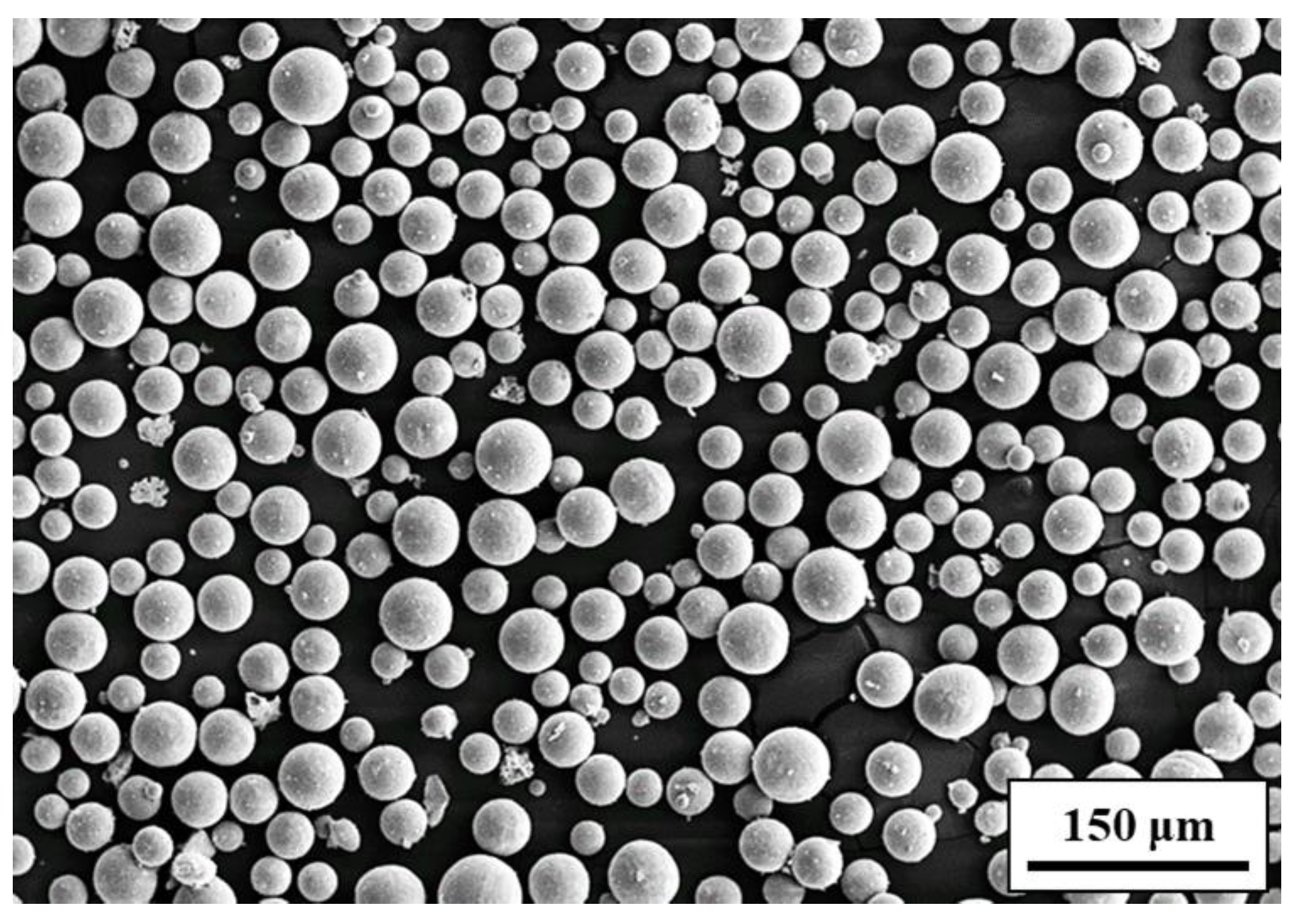
| Particle Size | Laser Power | Laser Radius | Scanning Velocity | Layer Thickness |
|---|---|---|---|---|
| 15–53 μm | 170 W | 35 μm | 1000 mm/s | 60 μm |
| Element | Al | V | Zn | O | C | N | Ti |
|---|---|---|---|---|---|---|---|
| Wt.% | 5.7 | 3.7 | 0.3 | 0.2 | 0.1 | 0.1 | Bal. |
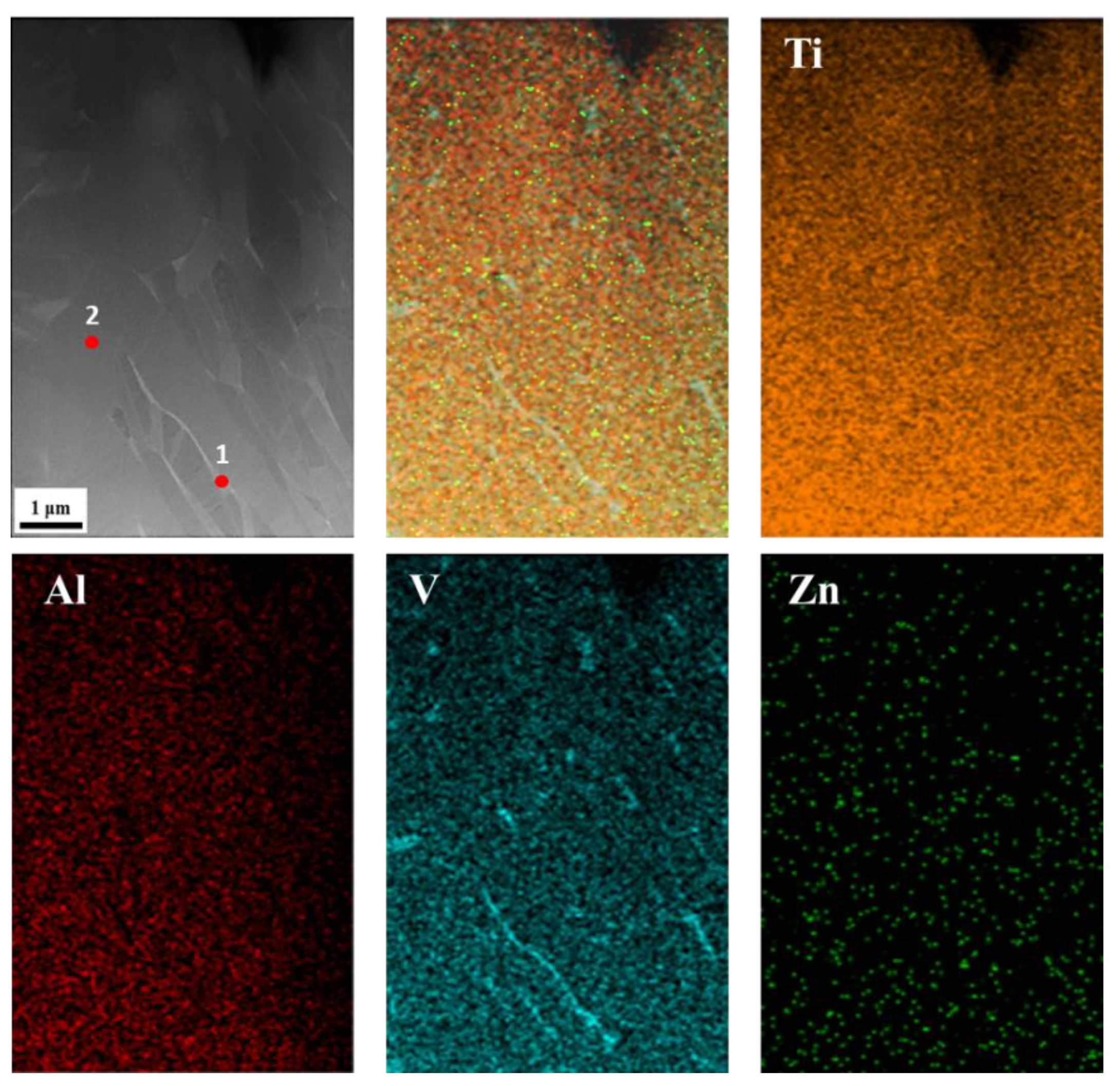
| Element | Ti | Al | V | Zn | |
|---|---|---|---|---|---|
| at.% | 1 | 75.27 | 3.58 | 21.09 | 0.07 |
| 2 | 87.26 | 9.42 | 3.32 | 0.00 | |
Disclaimer/Publisher’s Note: The statements, opinions and data contained in all publications are solely those of the individual author(s) and contributor(s) and not of MDPI and/or the editor(s). MDPI and/or the editor(s) disclaim responsibility for any injury to people or property resulting from any ideas, methods, instructions or products referred to in the content. |
© 2023 by the authors. Licensee MDPI, Basel, Switzerland. This article is an open access article distributed under the terms and conditions of the Creative Commons Attribution (CC BY) license (https://creativecommons.org/licenses/by/4.0/).
Share and Cite
Cheng, Y.-J.; Hung, F.-Y.; Zhao, J.-R. Microstructural Characteristics and Material Failure Mechanism of SLM Ti-6Al-4V-Zn Alloy. Materials 2023, 16, 7341. https://doi.org/10.3390/ma16237341
Cheng Y-J, Hung F-Y, Zhao J-R. Microstructural Characteristics and Material Failure Mechanism of SLM Ti-6Al-4V-Zn Alloy. Materials. 2023; 16(23):7341. https://doi.org/10.3390/ma16237341
Chicago/Turabian StyleCheng, Yi-Jin, Fei-Yi Hung, and Jun-Ren Zhao. 2023. "Microstructural Characteristics and Material Failure Mechanism of SLM Ti-6Al-4V-Zn Alloy" Materials 16, no. 23: 7341. https://doi.org/10.3390/ma16237341
APA StyleCheng, Y.-J., Hung, F.-Y., & Zhao, J.-R. (2023). Microstructural Characteristics and Material Failure Mechanism of SLM Ti-6Al-4V-Zn Alloy. Materials, 16(23), 7341. https://doi.org/10.3390/ma16237341