
Study on Joint Connection Performance of an Innovative Tooth Groove Connection and Vertical Reinforcement Lapping in Reserved Hole


Abstract
:1. Introduction
2. Materials and Methods
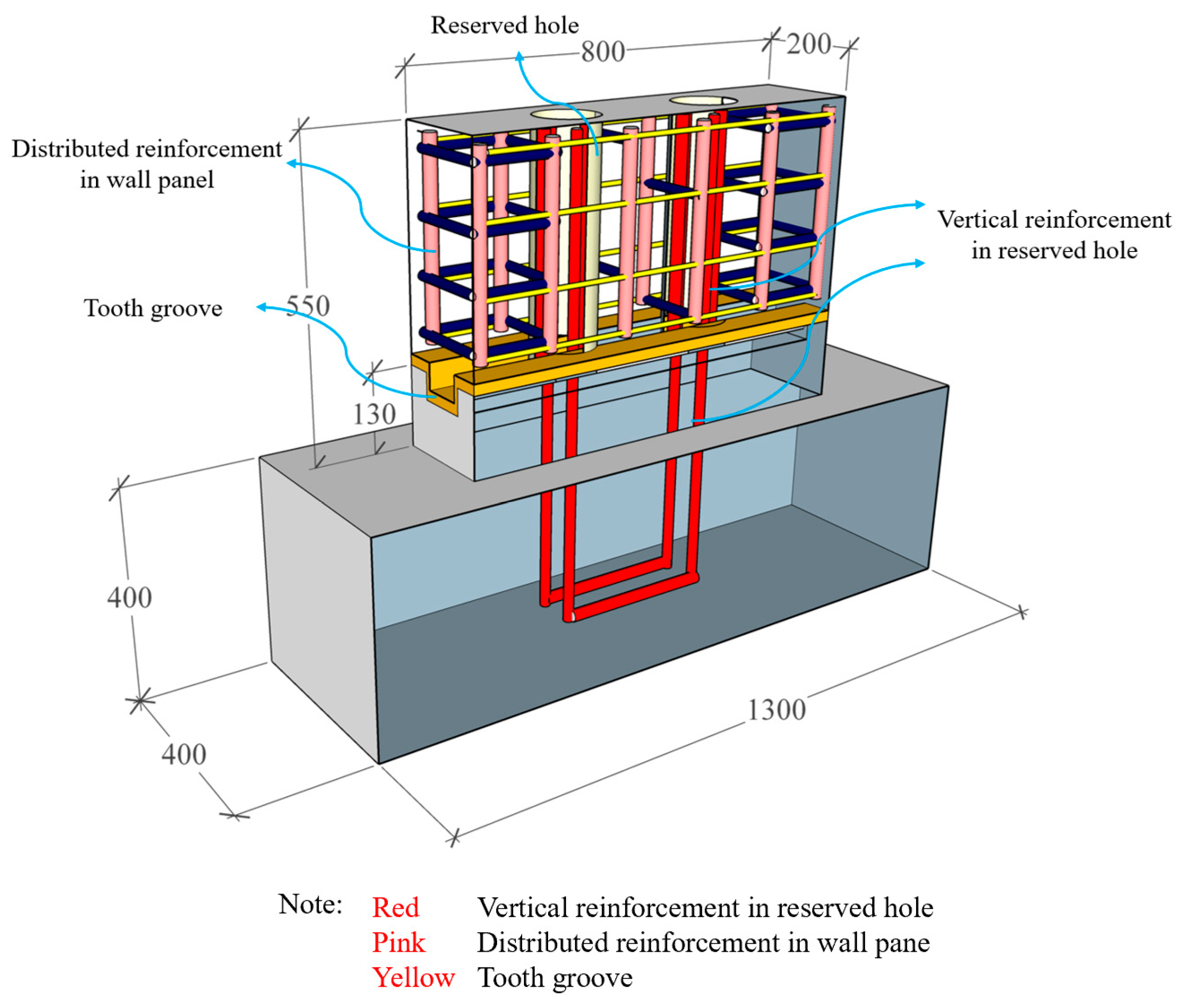
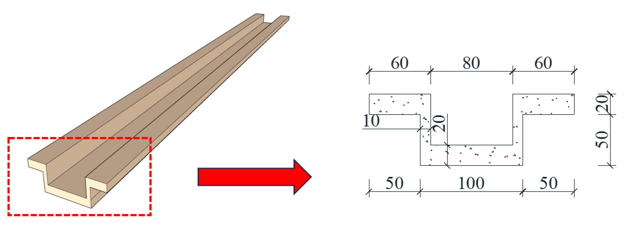
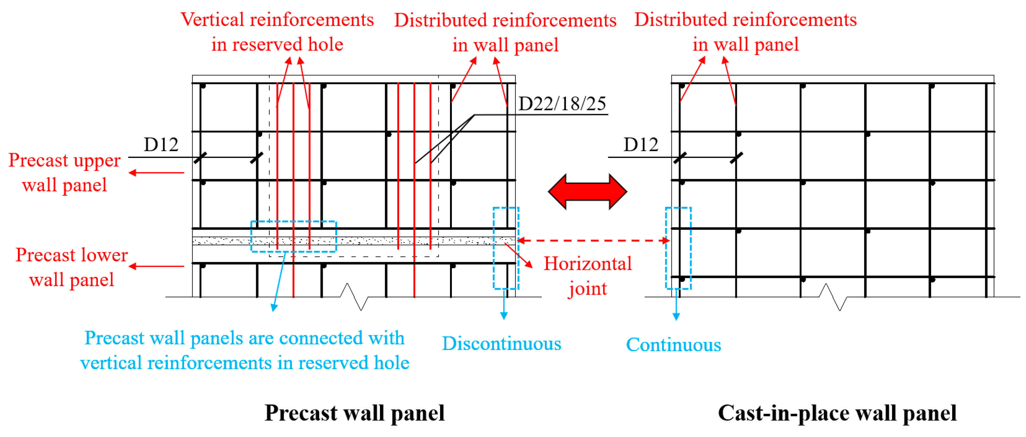
2.1. Connection Technology
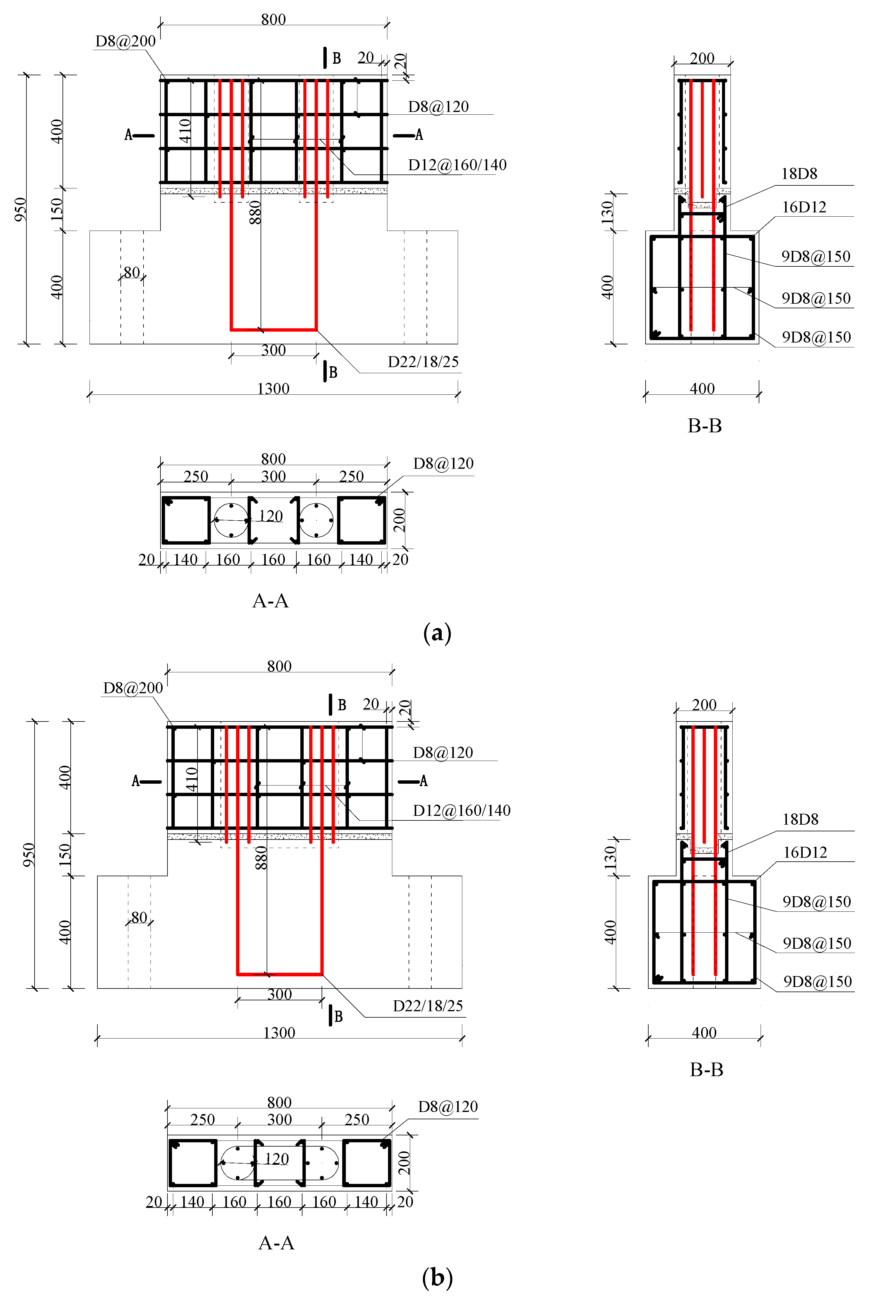
2.2. Design of Specimen
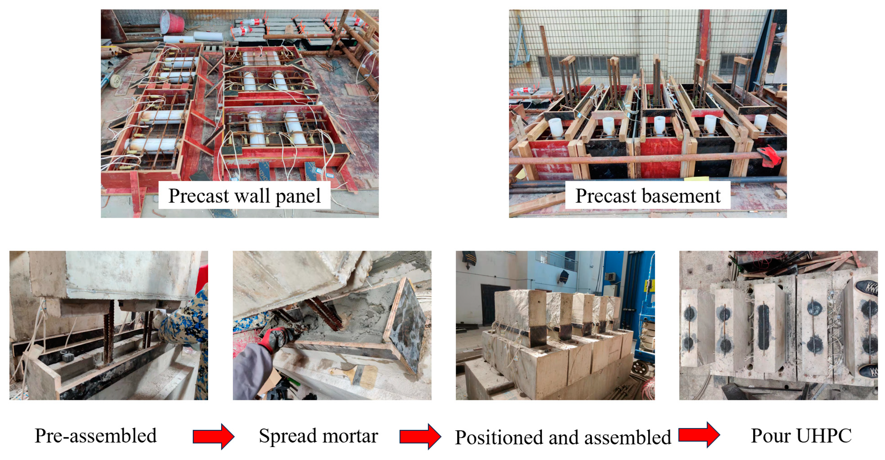
2.3. Fabrication and Assembly
2.4. Material Properties
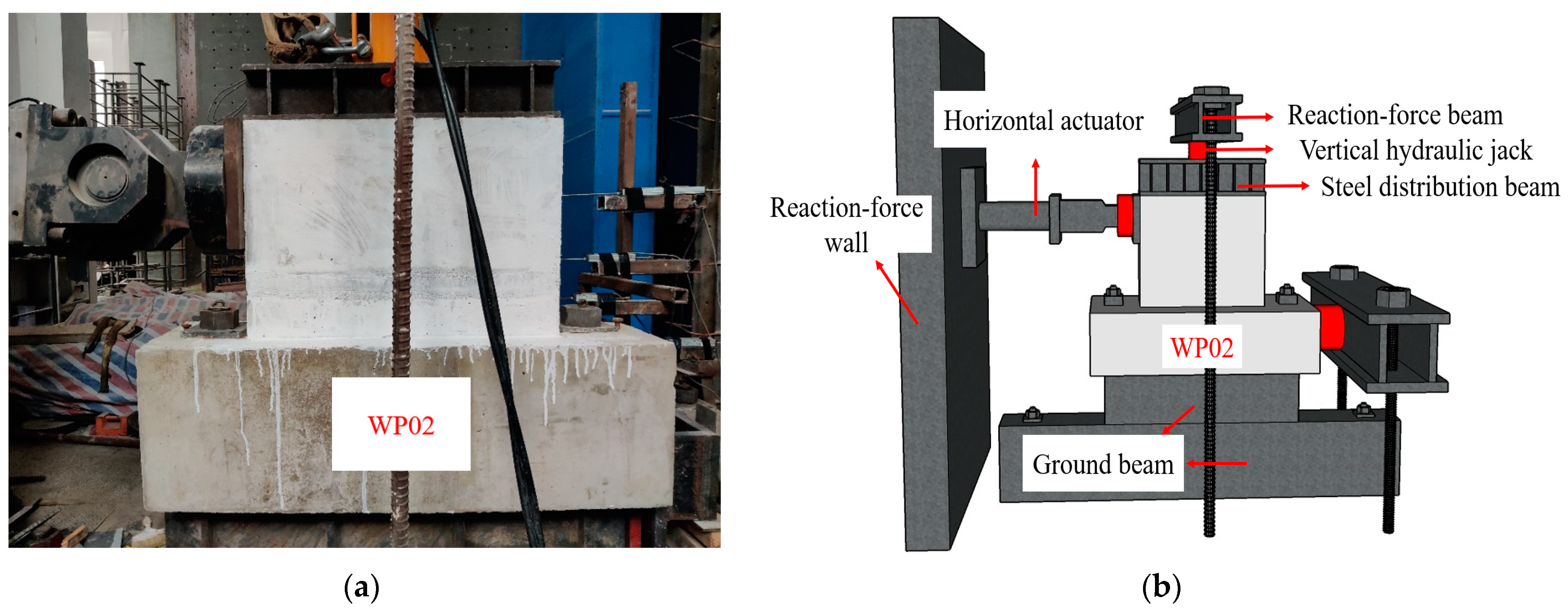
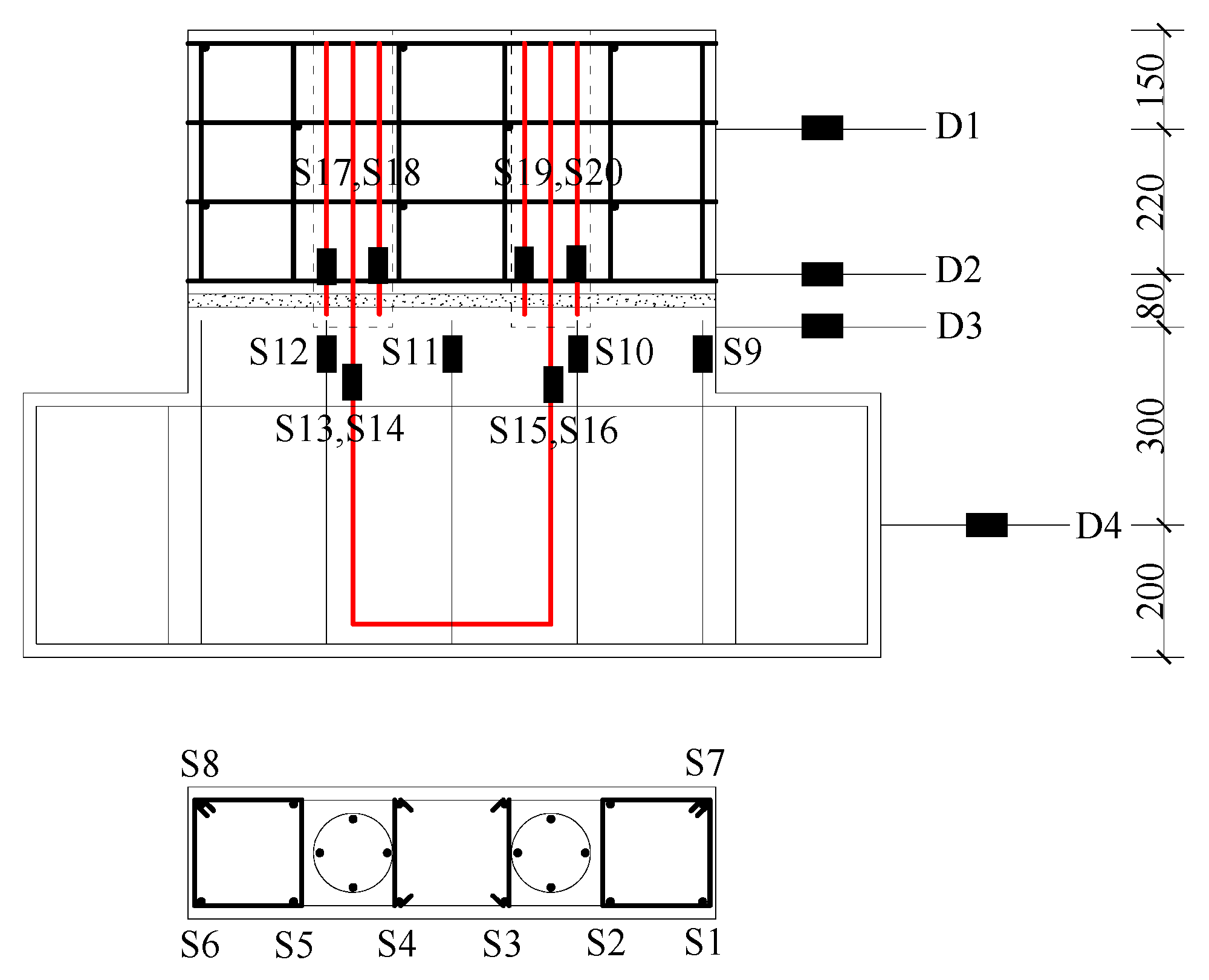
2.5. Test Procedure
3. Results and Discussion
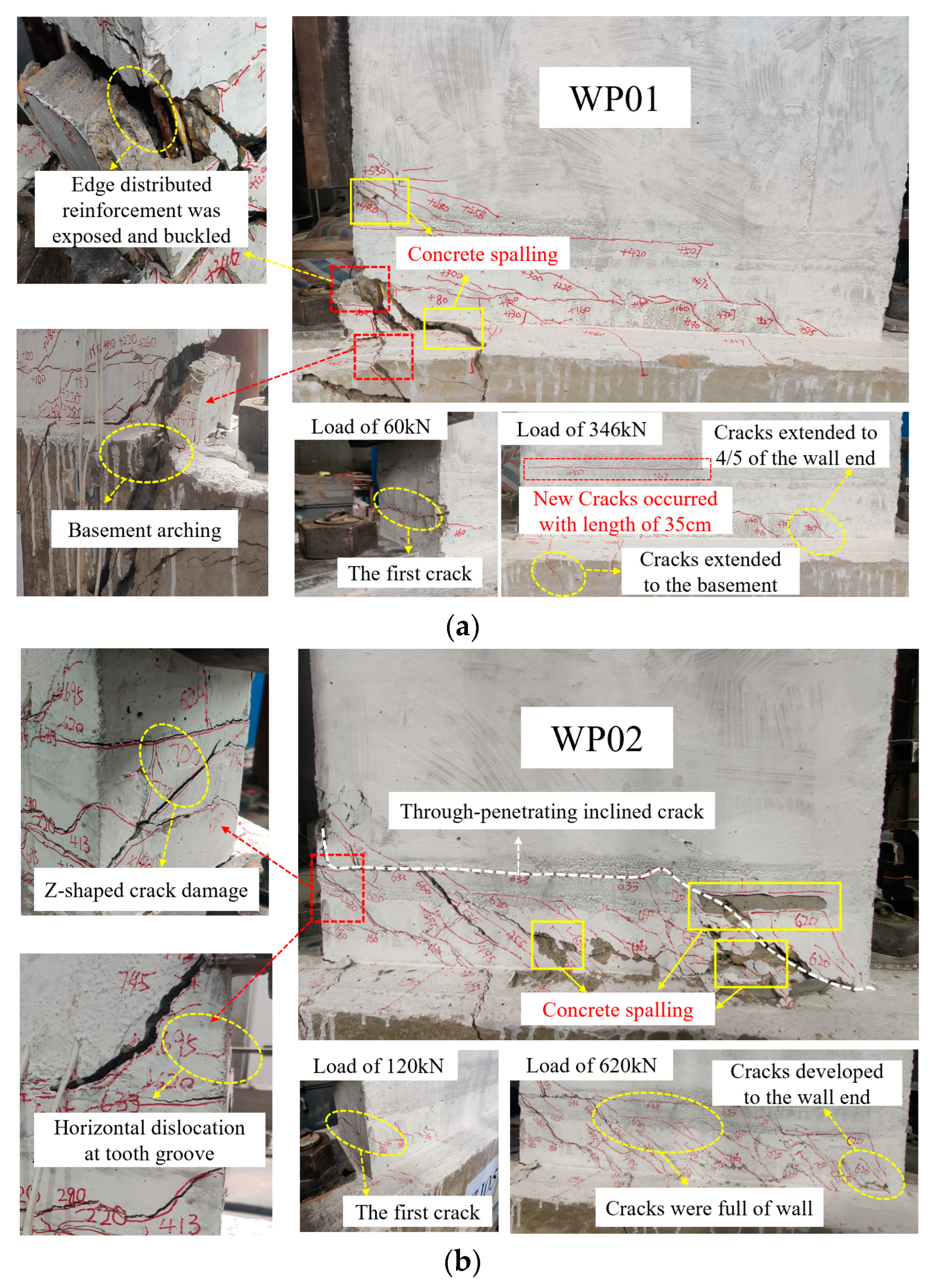
3.1. Test Phenomena and Failure Modes
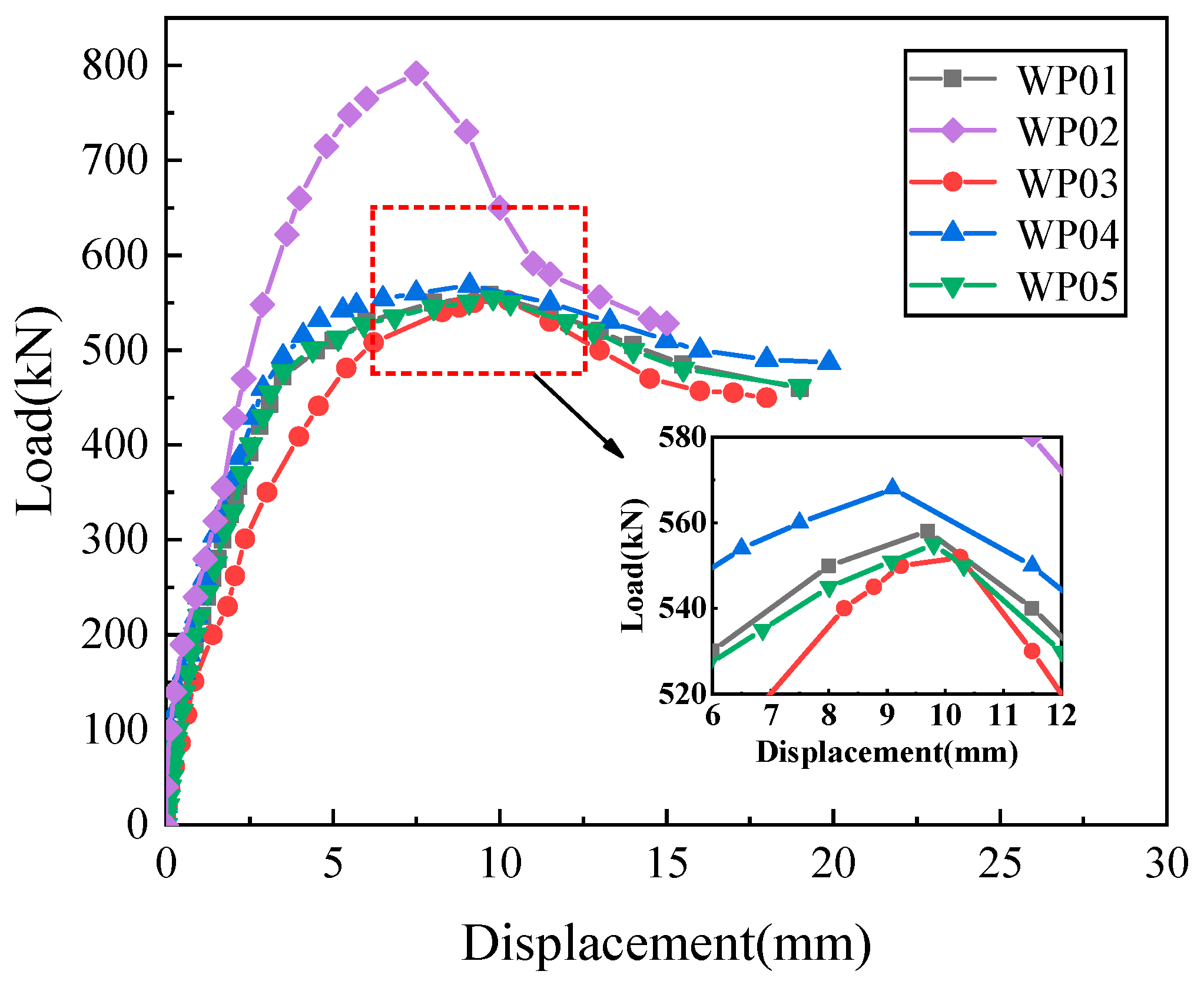
3.2. Load–Displacement Curve
3.3. Ductility
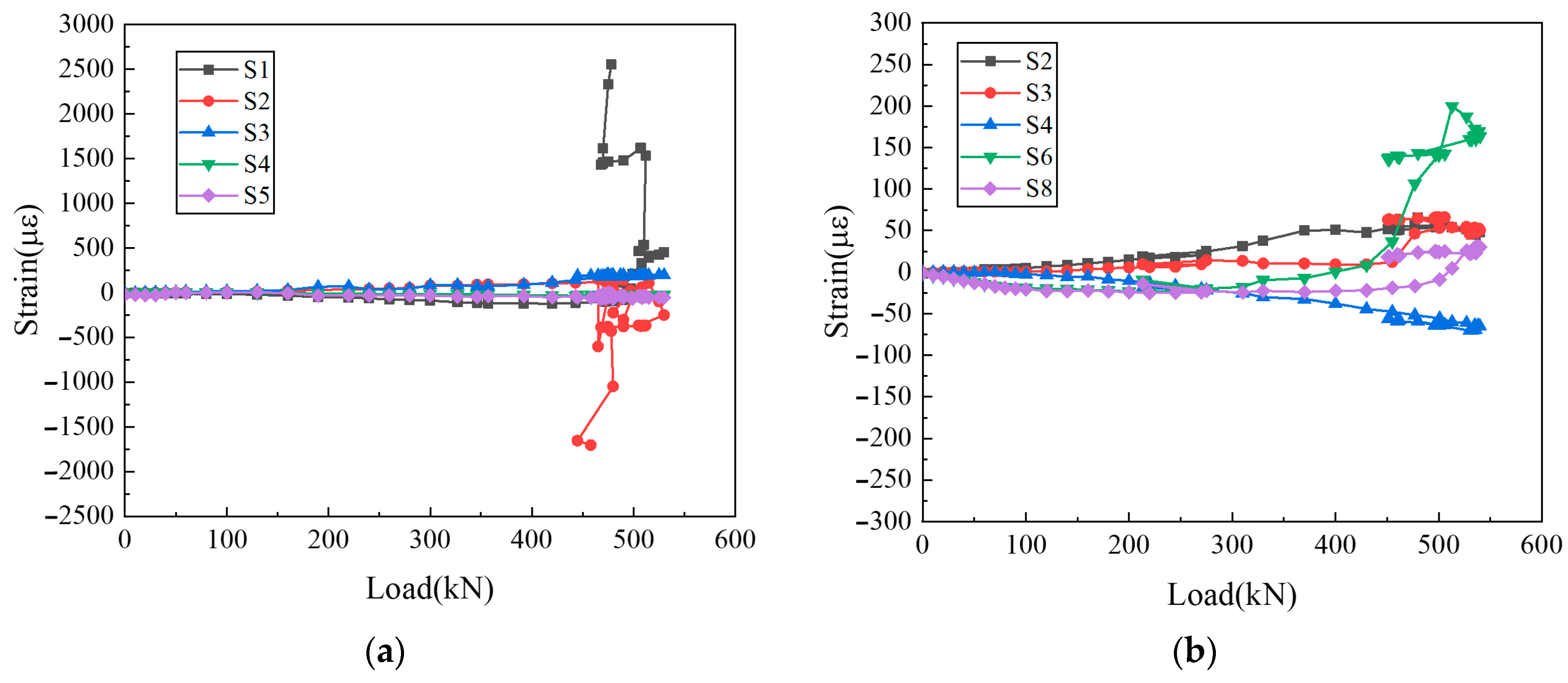
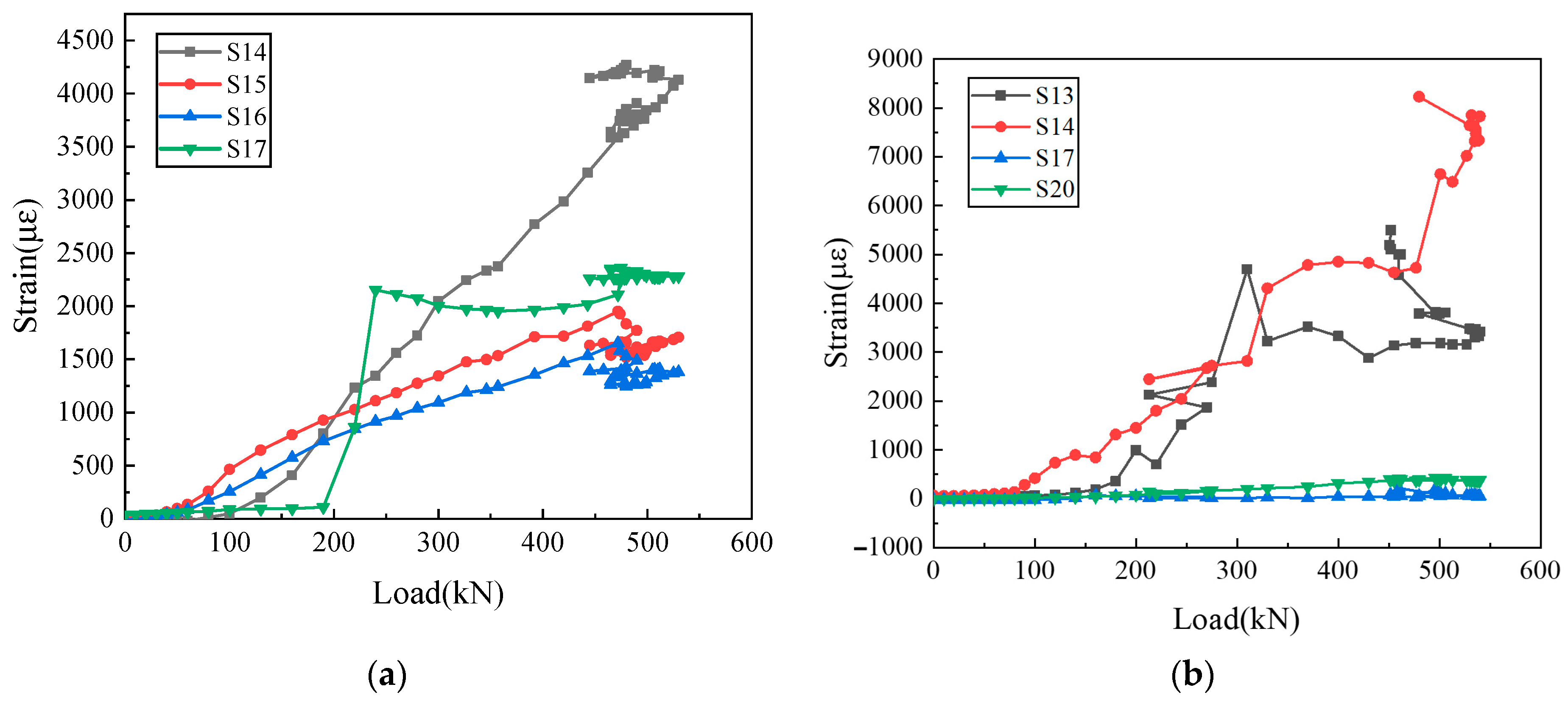
3.4. Steel Strain
4. Simulation
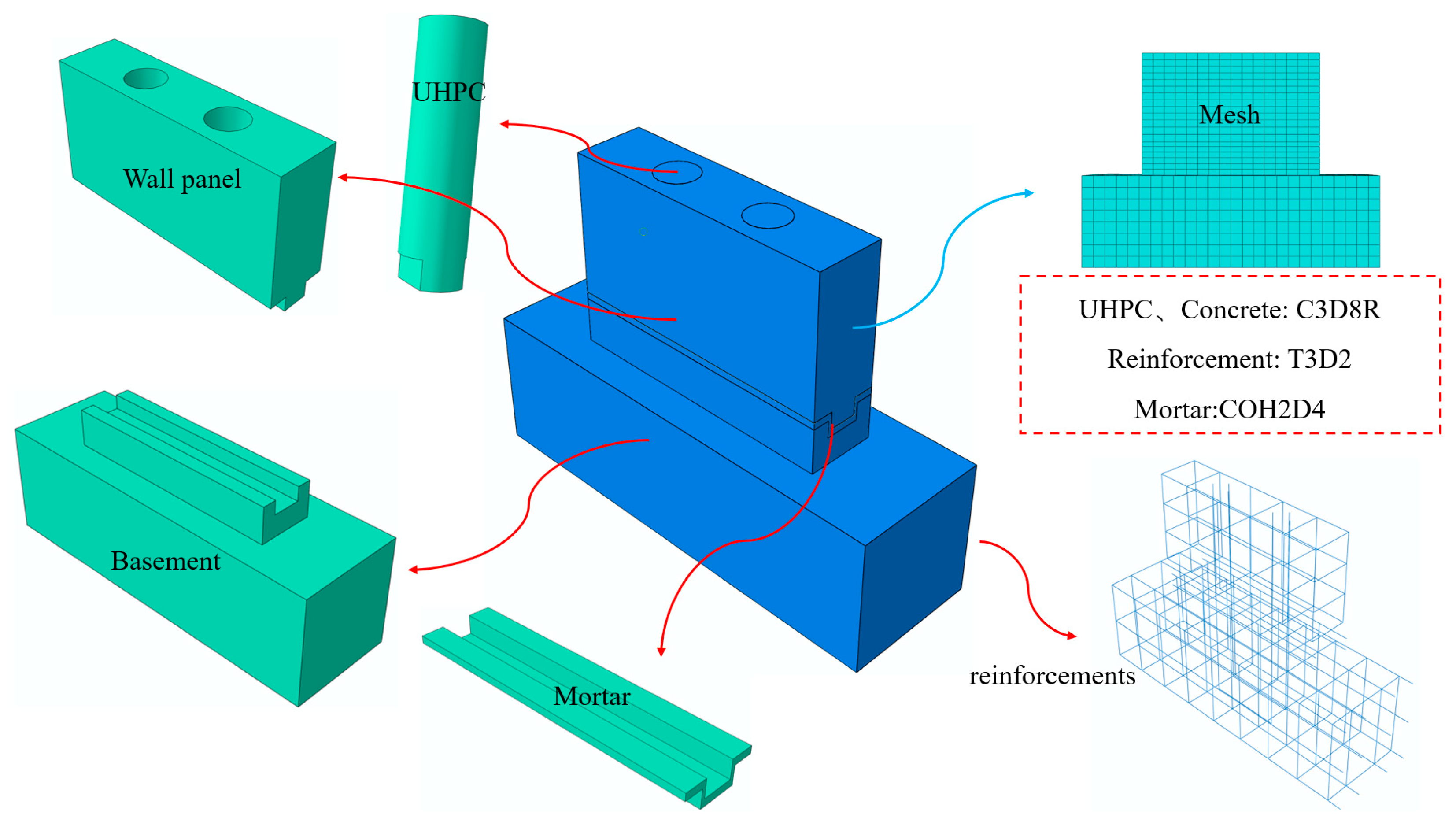
4.1. Finite Element (FE) Modeling
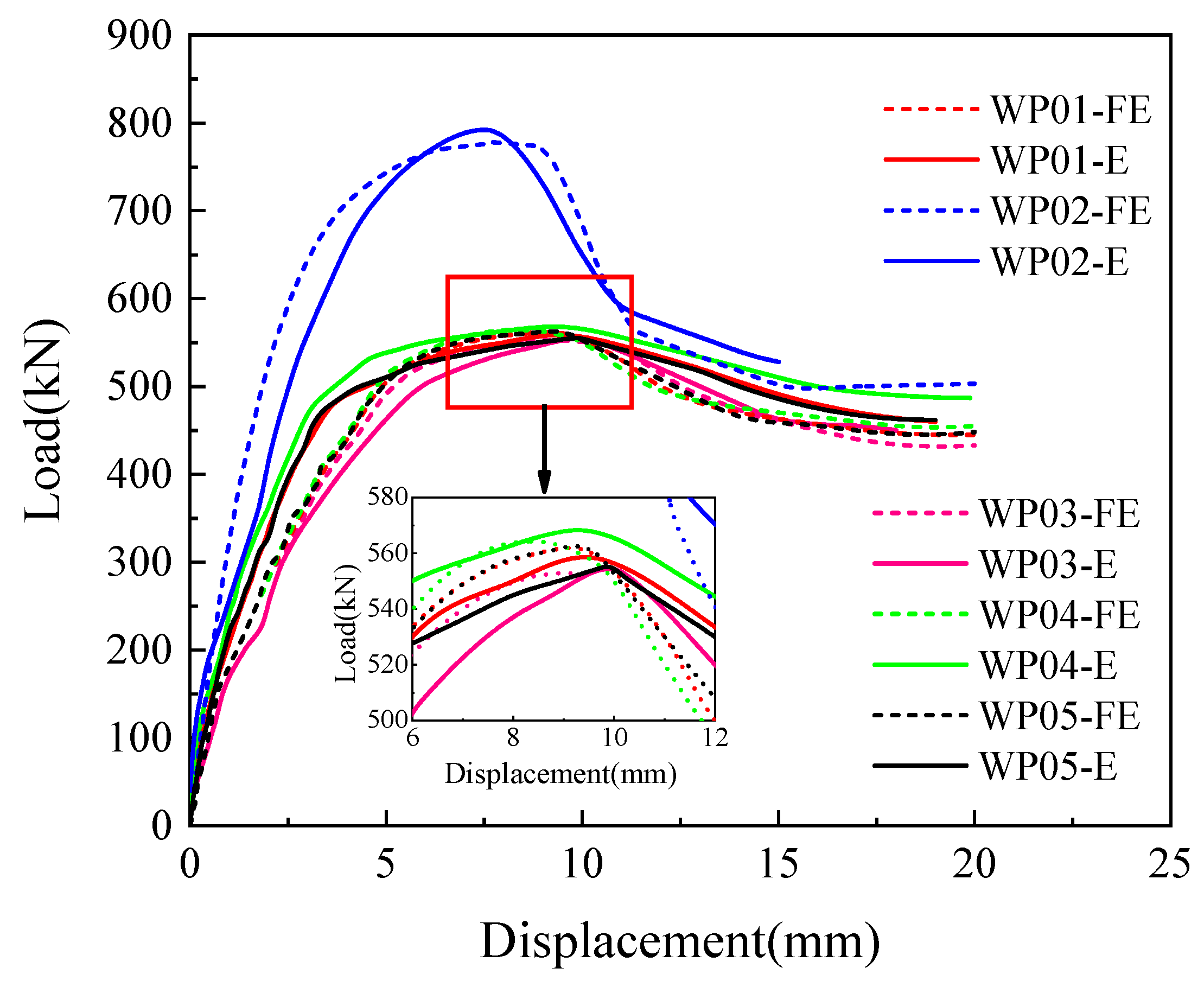
4.2. Model Verification
4.3. Parametric Analysis
4.3.1. Axial Compression Ratio
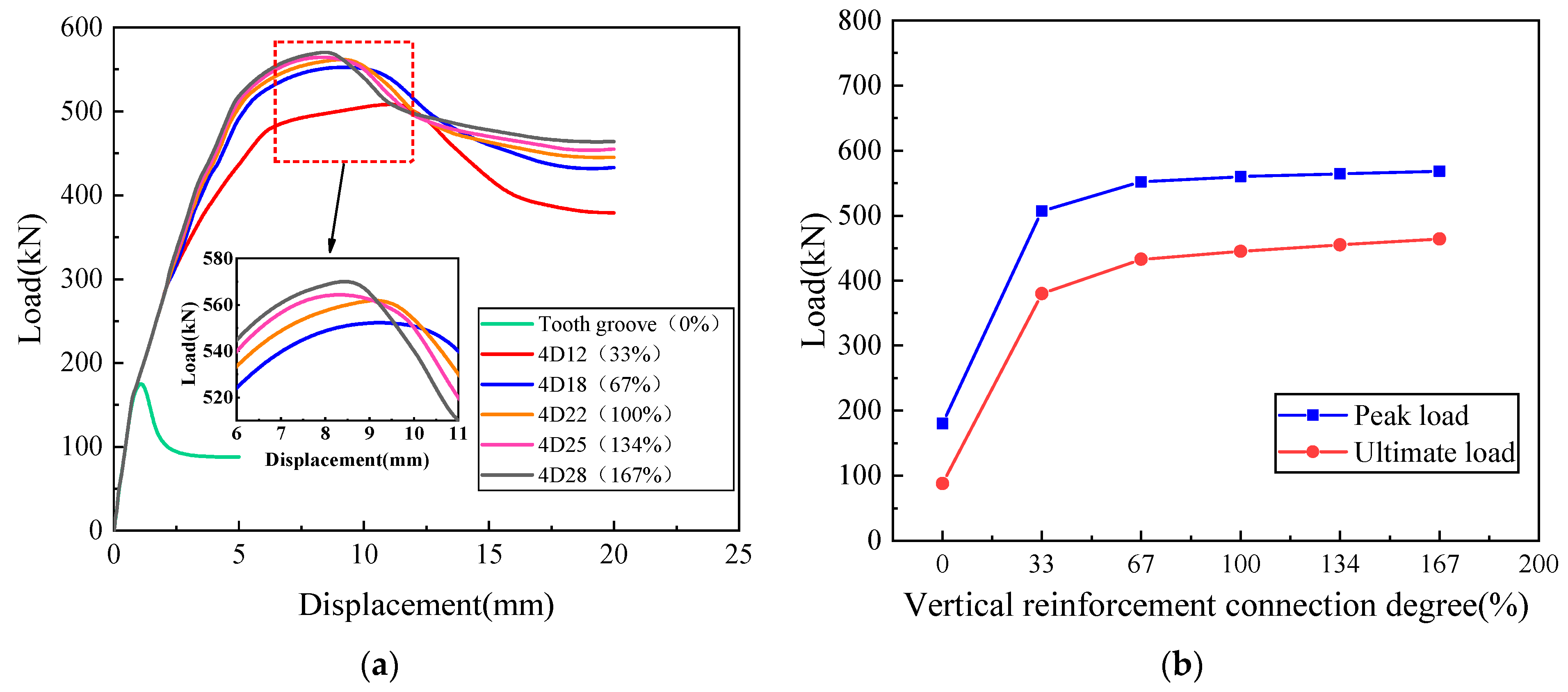
4.3.2. Vertical Reinforcement Connection Degree
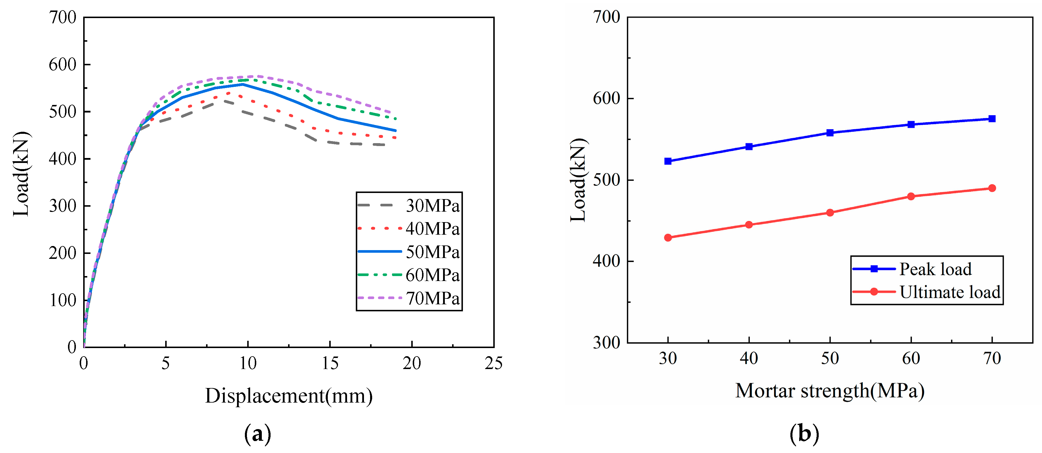
4.3.3. Mortar Strength
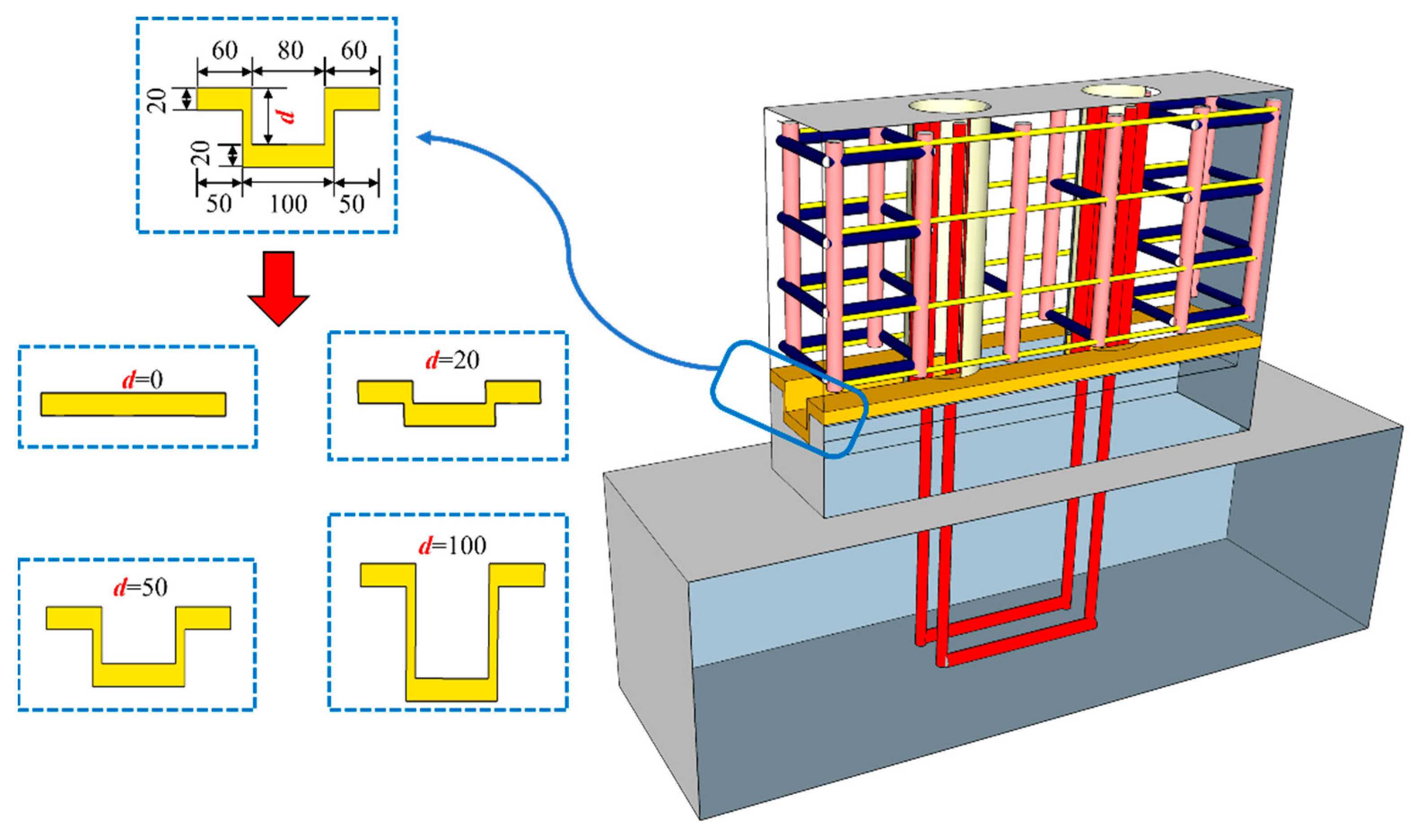
4.3.4. Tooth Groove Depth
5. Conclusions
- (1)
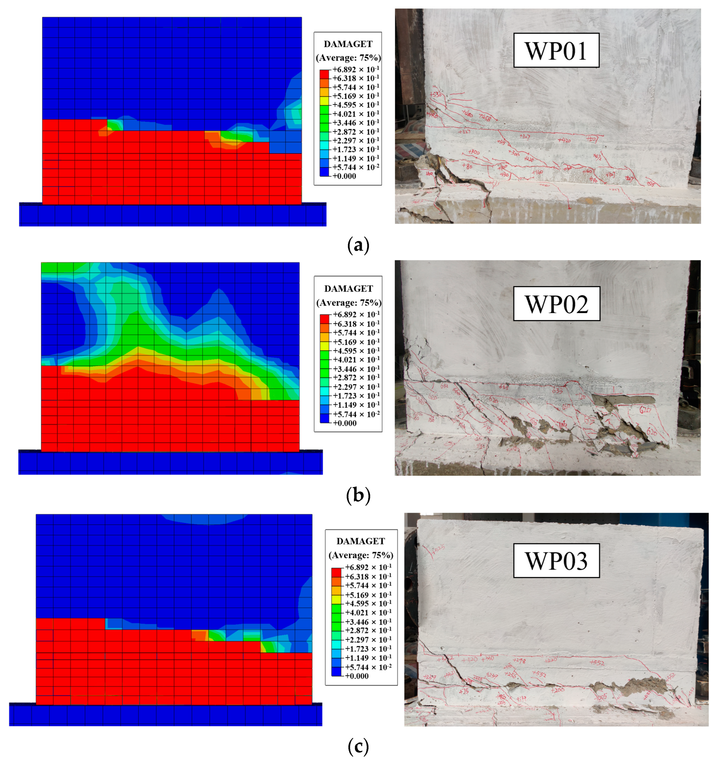
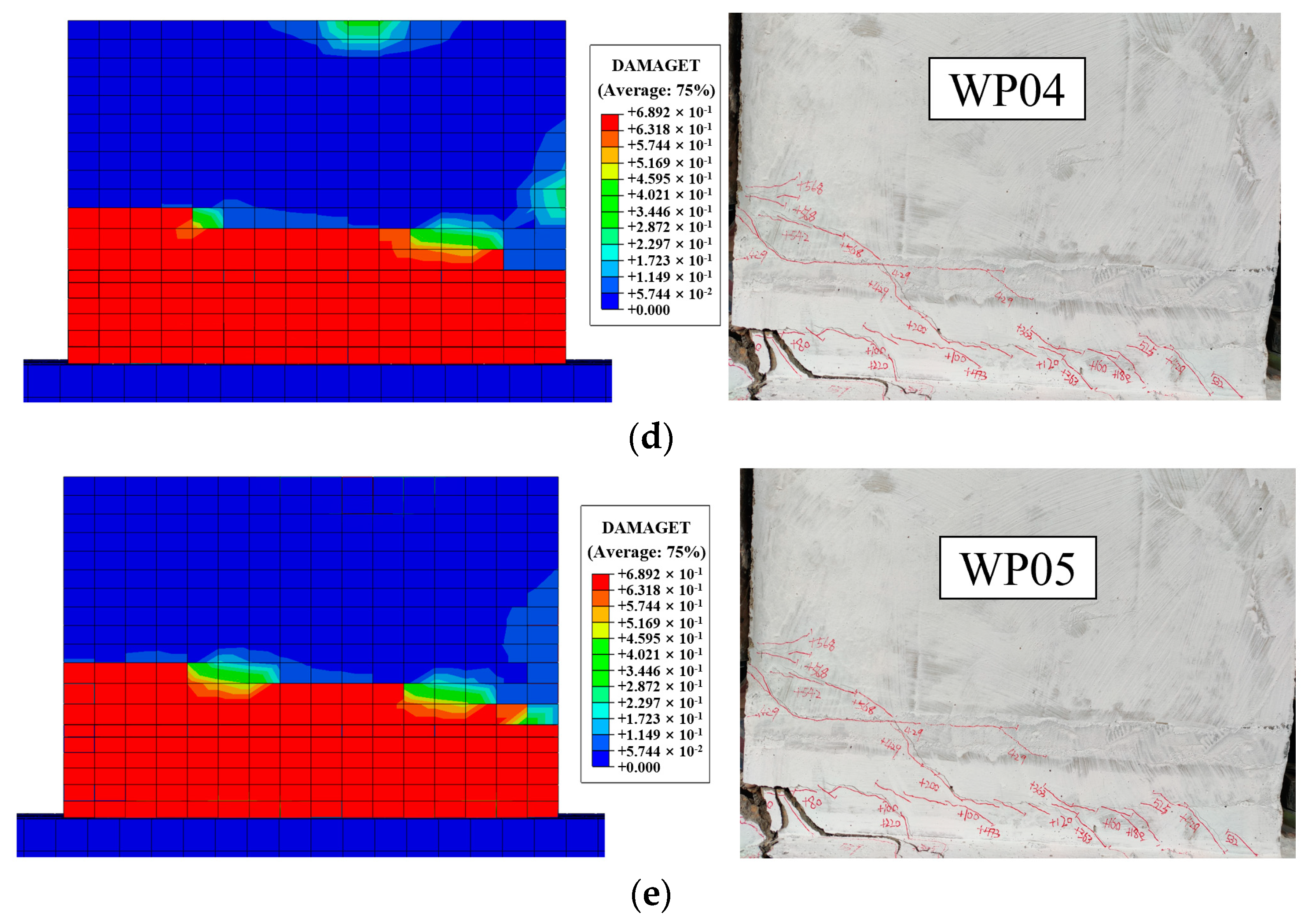
- The typical failure mode of the specimens with a tooth groove connection and vertical reinforcement lapping in the reserved hole was the horizontal through-penetrating inclined crack at the tooth groove connection. The distributed reinforcements mainly served a structural role, and the effective stress transfer at the horizontal joint was mainly achieved through the tooth groove interlocking action and the vertical reinforcements and UHPC in reserved holes. This innovative tooth groove connection and vertical reinforcement lapping in reserved hole method showed excellent connection performance, with the advantages of simple structure, convenient positioning, no template, and efficient assembly.
- (2)
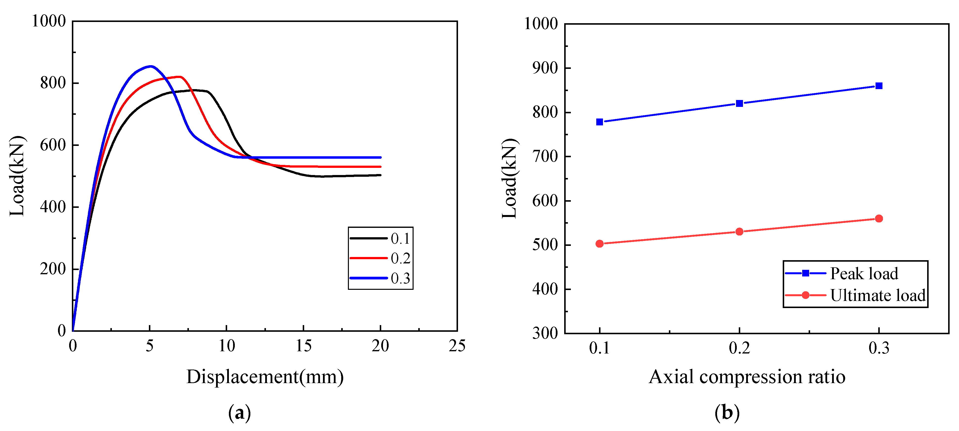
- With the increase in the axial compression ratio and vertical reinforcement connection degree, the joint connection performance of the specimens with tooth groove connection and vertical reinforcement lapping in the reserved hole significantly increased. However, when the vertical reinforcement connection degree was too large, the improvement of the joint connection performance was not obvious, and excessive reinforcement would cause waste. It was suggested that the reasonable value of the vertical reinforcement connection degree was 67–100%. In addition, the joint connection performance of the specimens with the reserved circular hole and the rounded rectangle hole was not significantly different and could be selected according to construction needs.
- (3)
- The finite element model of the specimens with tooth groove connection and vertical reinforcement lapping in the reserved hole was established, and its accuracy was verified. Through parameter analysis, it was found that with the increase in mortar strength and tooth groove depth, the joint connection performance improved. The reason was that increasing the mortar strength can improve the bond behavior between the interface of the precast concrete and the mortar, while increasing the tooth groove depth can strengthen the interlocking and friction actions. Considering the issues of hoisting, assembly, and transportation, it was recommended that the reasonable tooth groove depth be 50–100 mm.
- (4)
- In this paper, UHPC with ultra-high mechanical properties and durability was explicitly designated as the grouting material in reserved holes, which come with certain limitations. However, grouting materials with different compressive strengths and fluidities would affect the anchoring effect and grouting compactness of the lapping section. Therefore, the effect of different grouting materials on joint connection performance should be further studied in the future.
Author Contributions
Funding
Institutional Review Board Statement
Informed Consent Statement
Data Availability Statement
Acknowledgments
Conflicts of Interest
References
- Chang, H.; Song, X.; Qian, Y.; Ma, R.; Liu, N.; Xia, J.; Zhang, L. Experimental investigation of assembly-oriented steel column-beam connection with transverse reverse channels for prefabricated structures. Structures 2023, 56, 104908. [Google Scholar] [CrossRef]
- Navaratnam, S.; Ngo, T.; Gunawardena, T.; Henderson, D. Performance review of prefabricated building systems and future research in Australia. Buildings 2019, 9, 38. [Google Scholar] [CrossRef]
- Zhu, L.; Kong, L.; Zhang, C. Numerical study on hysteretic behaviour of horizontal-connection and energy-dissipation structures developed for prefabricated shear walls. Appl. Sci. 2020, 10, 1240. [Google Scholar] [CrossRef]
- Chang, R.; Zhang, N.; Gu, Q. A Review on Mechanical and Structural Performances of Precast Concrete Buildings. Buildings 2023, 13, 1575. [Google Scholar] [CrossRef]
- Hu, Z.; Shah, Y.I.; Yao, P. Experimental and numerical study on interface bond strength and anchorage performance of steel bars within prefabricated concrete. Materials 2021, 14, 3713. [Google Scholar] [CrossRef] [PubMed]
- Torra-Bilal, I.; Mahamid, M.; Baran, E. Cyclic behaviour of precast beam-to-column connections: An experimental and numerical investigation. Structures 2022, 35, 939–957. [Google Scholar] [CrossRef]
- de Lima Araújo, D.; Prado, L.P.; da Silva, E.B.; El Debs, M.K. Temporary beam-to-column connection for precast concrete frame assembly. Eng. Struct. 2018, 171, 529–544. [Google Scholar] [CrossRef]
- Ding, K.; Zhang, Y. Experimental study on seismic performance of fabricated bolted joint under low-cycle reciprocating loads. Results Eng. 2021, 9, 100208. [Google Scholar] [CrossRef]
- Guo, H.; Zhang, J.; Wang, C. Experimental study on influence of connection defects on joint strength of half-grouted sleeve splicing of rebar. Adv. Civ. Eng. 2020, 2020, 1–15. [Google Scholar] [CrossRef]
- Jin, Z.; Xia, S.; Cao, H.; Geng, X.; Cheng, Z.; Sun, H.; Jia, M.; Liu, Q.; Sun, J. Evaluation and Optimization of Sustainable Development Level of Construction Industrialization: Case Beijing-Tianjin-Hebei Region. Sustainability 2022, 14, 8245. [Google Scholar] [CrossRef]
- Li, D.-b.; Chai, Y.-k.; Li, W.-l.; Xiang, R. Experimental study and finite element analysis of seismic behaviour of novel precast prestressed concrete frames. Structures 2022, 38, 402–415. [Google Scholar] [CrossRef]
- Yan, X.; Wang, S.; Huang, C.; Qi, A.; Hong, C. Experimental study of a new precast prestressed concrete joint. Appl. Sci. 2018, 8, 1871. [Google Scholar] [CrossRef]
- Li, H.; Chen, W.; Hao, H. Dynamic response of precast concrete beam with wet connection subjected to impact loads. Eng. Struct. 2019, 191, 247–263. [Google Scholar] [CrossRef]
- Singhal, S.; Chourasia, A.; Chellappa, S.; Parashar, J. Precast reinforced concrete shear walls: State of the art review. Struct. Concr. 2019, 20, 886–898. [Google Scholar] [CrossRef]
- Yan, Q.; Chen, T.; Xie, Z. Seismic experimental study on a precast concrete beam-column connection with grout sleeves. Eng. Struct. 2018, 155, 330–344. [Google Scholar] [CrossRef]
- Hutchinson, R.L.; Rizkalla, S.H.; Lau, M.; Heuvel, S. Horizontal post-tensioned connections for precast concrete loadbearing shear wall panels. PCI J. 1991, 36, 64–76. [Google Scholar] [CrossRef]
- Holden, T.; Restrepo, J.; Mander, J.B. Seismic performance of precast reinforced and prestressed concrete walls. J. Struct. Eng. 2003, 129, 286–296. [Google Scholar] [CrossRef]
- Smith, B.J.; Kurama, Y.C.; McGinnis, M.J. Design and measured behavior of a hybrid precast concrete wall specimen for seismic regions. J. Struct. Eng. 2011, 137, 1052–1062. [Google Scholar] [CrossRef]
- Fu, Y.; Fan, G.; Tao, L.; Yang, Y.; Wang, J. Seismic behavior of prefabricated steel reinforced concrete shear walls with new type connection mode. Structures 2022, 37, 483–503. [Google Scholar] [CrossRef]
- Zhao, F.; Xiong, F.; Cai, G.; Ge, Q.; Larbi, A.S. Seismic behavior and simplified hysteretic model of precast concrete wall panels with bolted connections under cyclic loading. Eng. Struct. 2023, 292, 116562. [Google Scholar] [CrossRef]
- Sun, J.; Wang, T.; Sun, H.; Ruan, S.; Qiu, H. Parametric study on lateral behavior of totally precast RC shear wall with horizontal bolted connection. Structures 2023, 57, 105100. [Google Scholar] [CrossRef]
- Liao, X.; Zhang, S.; Cao, Z.; Xiao, X. Seismic performance of a new type of precast shear walls with non-connected vertical distributed reinforcement. J. Build. Eng. 2021, 44, 103219. [Google Scholar] [CrossRef]
- Jia, L.; Li, Q.; Zhang, Y.; Zhao, W.; Du, M. Experimental study of the hysteretic behavior of prefabricated frame-shear wall structures with grouting sleeve connections. J. Build. Eng. 2022, 57, 104704. [Google Scholar] [CrossRef]
- Gao, Q.; Zhao, W. Experimental study on factors influencing the connection performance of grouted welded sleeves under uniaxial tensile loads. J. Build. Eng. 2021, 43, 103033. [Google Scholar] [CrossRef]
- Gu, Q.; Dong, G.; Wang, X.; Jiang, H.; Peng, S. Research on pseudo-static cyclic tests of precast concrete shear walls with vertical rebar lapping in grout-filled constrained hole. Eng. Struct. 2019, 189, 396–410. [Google Scholar] [CrossRef]
- Zhi, Q.; Guo, Z.; Xiao, Q.; Yuan, F.; Song, J. Quasi-static test and strut-and-tie modeling of precast concrete shear walls with grouted lap-spliced connections. Constr. Build. Mater. 2017, 150, 190–203. [Google Scholar] [CrossRef]
- Zhang, Z.; Li, S.; Liu, X.; Wang, D.; Liu, H. Experimental study on mechanical performance of slurry anchor connection of assembled shear wall. J. Build. Struct. 2019, 40, 189–197. [Google Scholar]
- Cheng, J.; Luo, X.; Cheng, Q.; Xing, M. Seismic performance of precast concrete walls with grouted sleeve connections using large-diameter bars. Soil Dyn. Earthq. Eng. 2023, 169, 107905. [Google Scholar] [CrossRef]
- Zhang, Y.; Li, D. Development and testing of precast concrete-filled square steel tube column-to-RC beam connections under cyclic loading. Constr. Build. Mater. 2021, 280, 122540. [Google Scholar] [CrossRef]
- Chen, Q.; Luo, X.; Xing, M.; Li, Z. Shaking table test of fully assembled precast concrete shear wall substructure with tooth groove and reserved hole concentrated reinforcement connection. J. Build. Eng. 2023, 76, 107151. [Google Scholar] [CrossRef]
- An, M.; Zhang, M. Experimental study on bonding performance between deformed steel bar and reactive powder concrete. China Railw. Sci. 2007, 2, 50–54. [Google Scholar]
- Ma, F.; Deng, M.; Sun, H.; Ye, W. Lap bonding performance of deformed steel bar / ultra-high performance concrete. Acta Mater. Compos. Sin. 2021, 38, 3912–3924. [Google Scholar]
- T/CECS 809-2021; Technical Specification of Multi-Story Building for Precast Concrete Wall-Slab Structures with Bolt Connection. China Building Industry Publisher:: Beijing, China, 2021.
- JGJ/T 70-2009; Standard for Test Method of Basic Performance of Building Mortar. China Building Industry Publisher: Beijing, China, 2009.
- GB/T 50081-2002; Standard for Test Methods of Mechanical Properties of Ordinary Concrete. China Building Industry Publisher: Beijing, China, 2003.
- GB/T 1499.2-2018; Hot-rolled Ribbed Steel Bars for Reinforcement of Concrete. China Standard Publisher: Beijing, China, 2018.
- Gusella, F.; Orlando, M. Failure analysis and retrofitting of reinforced concrete beams in existing moment resisting frames. Eng. Fail. Anal. 2023, 153, 107601. [Google Scholar] [CrossRef]
- Foraboschi, P. Bending load-carrying capacity of reinforced concrete beams subjected to premature failure. Materials 2019, 12, 3085. [Google Scholar] [CrossRef] [PubMed]
- Wang, D.; Wang, Z.; Smith, S.T.; Yu, T. Seismic performance of CFRP-confined circular high-strength concrete columns with high axial compression ratio. Constr. Build. Mater. 2017, 134, 91–103. [Google Scholar] [CrossRef]
- Seok, S.; Haikal, G.; Ramirez, J.A.; Lowes, L.N.; Lim, J. Finite element simulation of bond-zone behavior of pullout test of reinforcement embedded in concrete using concrete damage-plasticity model 2 (CDPM2). Eng. Struct. 2020, 221, 110984. [Google Scholar] [CrossRef]
- GB 50010-2010; Design Code for Concrete Structure. China Building Industry Publisher: Beijing, China, 2010.
- Langarudi, P.A.; Ebrahimnejad, M. Numerical study of the behavior of bolted shear connectors in composite slabs with steel deck. Structures 2020, 26, 501–515. [Google Scholar] [CrossRef]


| Specimen | Reserved Hole Type | Axial Compression Ratio | Vertical Reinforcement Connection Degree |
|---|---|---|---|
| WP01 | Circular hole | 0 | 4D22 (100%) |
| WP02 | Circular hole | 0.1 | 4D22 (100%) |
| WP03 | Circular hole | 0 | 4D18 (67%) |
| WP04 | Circular hole | 0 | 4D25 (134%) |
| WP05 | Rounded rectangle hole | 0 | 4D22 (100%) |
| Specification | Yield Strength fy/Mpa | Ultimate Strength fu/Mpa | Elongation δ/% |
|---|---|---|---|
| D8 | 453.6 | 635.0 | 20.4 |
| D12 | 435.4 | 553.0 | 21.6 |
| D18 | 447.7 | 625.3 | 28.4 |
| D22 | 447.9 | 628.1 | 28.4 |
| D25 | 465.8 | 655.6 | 26.3 |
| Materials | Dimension/mm | Load/kN | Compressive Strength fc/Mpa |
|---|---|---|---|
| Mortar | 70.7 × 70.7 × 70.7 | 165 | 50.5 |
| UHPC | 100 × 100 × 100 | 1398 | 139.8 |
| Concrete | 150 × 150 × 150 | 648 | 28.8 |
| Specimen | Fcr/kN | ∆cr/mm | Fy/kN | ∆y/mm | Fp/kN | ∆p/mm | Fu/kN | ∆u/mm | ∆h/mm | μ |
|---|---|---|---|---|---|---|---|---|---|---|
| WP01 | 60 | 0.12 | 472 | 3.68 | 558 | 9.71 | 461 | 19.00 | / | 5.16 |
| WP02 | 120 | 0.19 | 675 | 4.25 | 792 | 7.50 | 528 | 14.40 | 1.8 | 3.39 |
| WP03 | 75 | 0.36 | 441 | 4.57 | 552 | 10.26 | 448 | 17.00 | 2.6 | 3.72 |
| WP04 | 60 | 0.07 | 493 | 3.60 | 568 | 9.08 | 480 | 19.88 | / | 5.52 |
| WP05 | 50 | 0.16 | 477 | 3.65 | 555 | 9.82 | 462 | 19.91 | / | 5.45 |
| Specimen | Fy/kN | Fy,s/kN | Fp/kN | Fp,s/kN | Fy,s/Fy | Fp,s/Fp |
|---|---|---|---|---|---|---|
| WP01 | 472 | 461 | 558 | 560 | 0.98 | 1 |
| WP02 | 675 | 713 | 792 | 778 | 1.06 | 0.98 |
| WP03 | 441 | 455 | 552 | 555 | 1.03 | 1.01 |
| WP04 | 493 | 470 | 568 | 564 | 0.95 | 0.99 |
| WP05 | 477 | 463 | 555 | 558 | 0.97 | 1.01 |
| Average value | 0.998 | 0.998 | ||||
| Coefficient of variation | 0.04 | 0.01 | ||||
Disclaimer/Publisher’s Note: The statements, opinions and data contained in all publications are solely those of the individual author(s) and contributor(s) and not of MDPI and/or the editor(s). MDPI and/or the editor(s) disclaim responsibility for any injury to people or property resulting from any ideas, methods, instructions or products referred to in the content. |
© 2023 by the authors. Licensee MDPI, Basel, Switzerland. This article is an open access article distributed under the terms and conditions of the Creative Commons Attribution (CC BY) license (https://creativecommons.org/licenses/by/4.0/).
Share and Cite
Luo, X.; He, Y.; Chen, Q.; Chen, L. Study on Joint Connection Performance of an Innovative Tooth Groove Connection and Vertical Reinforcement Lapping in Reserved Hole. Materials 2023, 16, 7371. https://doi.org/10.3390/ma16237371
Luo X, He Y, Chen Q, Chen L. Study on Joint Connection Performance of an Innovative Tooth Groove Connection and Vertical Reinforcement Lapping in Reserved Hole. Materials. 2023; 16(23):7371. https://doi.org/10.3390/ma16237371
Chicago/Turabian StyleLuo, Xiaoyong, Yang He, Qi Chen, and Linsong Chen. 2023. "Study on Joint Connection Performance of an Innovative Tooth Groove Connection and Vertical Reinforcement Lapping in Reserved Hole" Materials 16, no. 23: 7371. https://doi.org/10.3390/ma16237371
APA StyleLuo, X., He, Y., Chen, Q., & Chen, L. (2023). Study on Joint Connection Performance of an Innovative Tooth Groove Connection and Vertical Reinforcement Lapping in Reserved Hole. Materials, 16(23), 7371. https://doi.org/10.3390/ma16237371