
Mechanical and Microstructural Properties of Thermally Sprayed Metallic Materials in Compression Tests over a Vast Range of Strain Rates

Abstract
:1. Introduction
2. Experimental Set-Up and Test Description—Static and Dynamic Tests
2.1. General Remarks
2.2. Static Tests
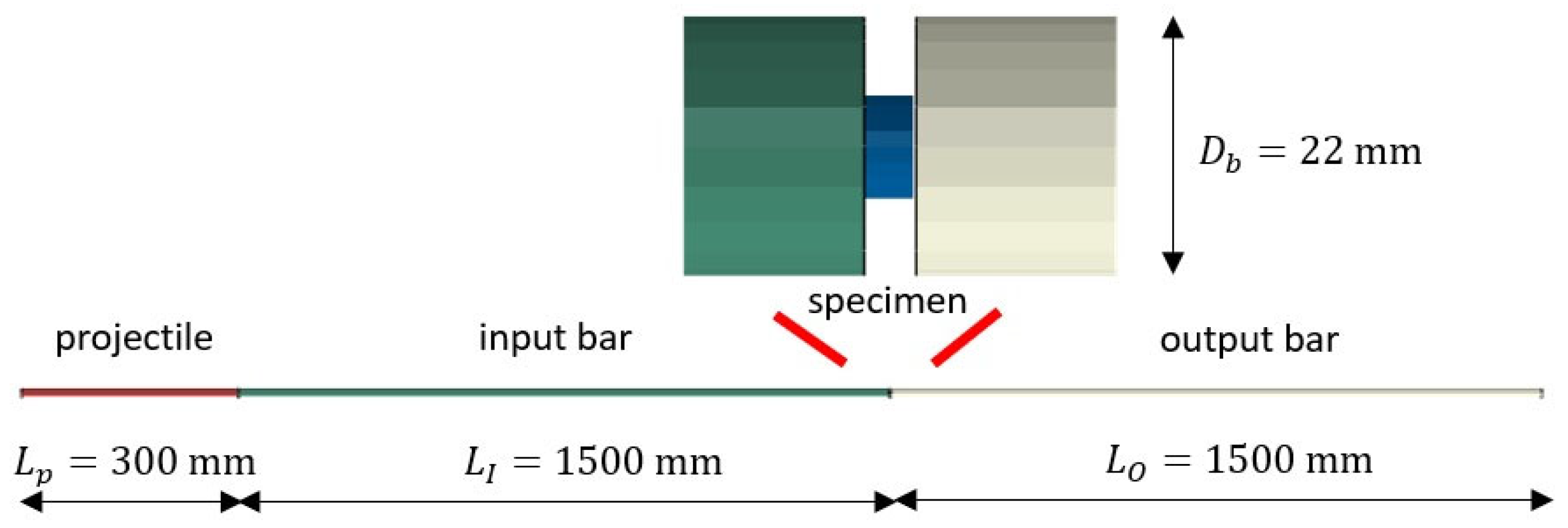
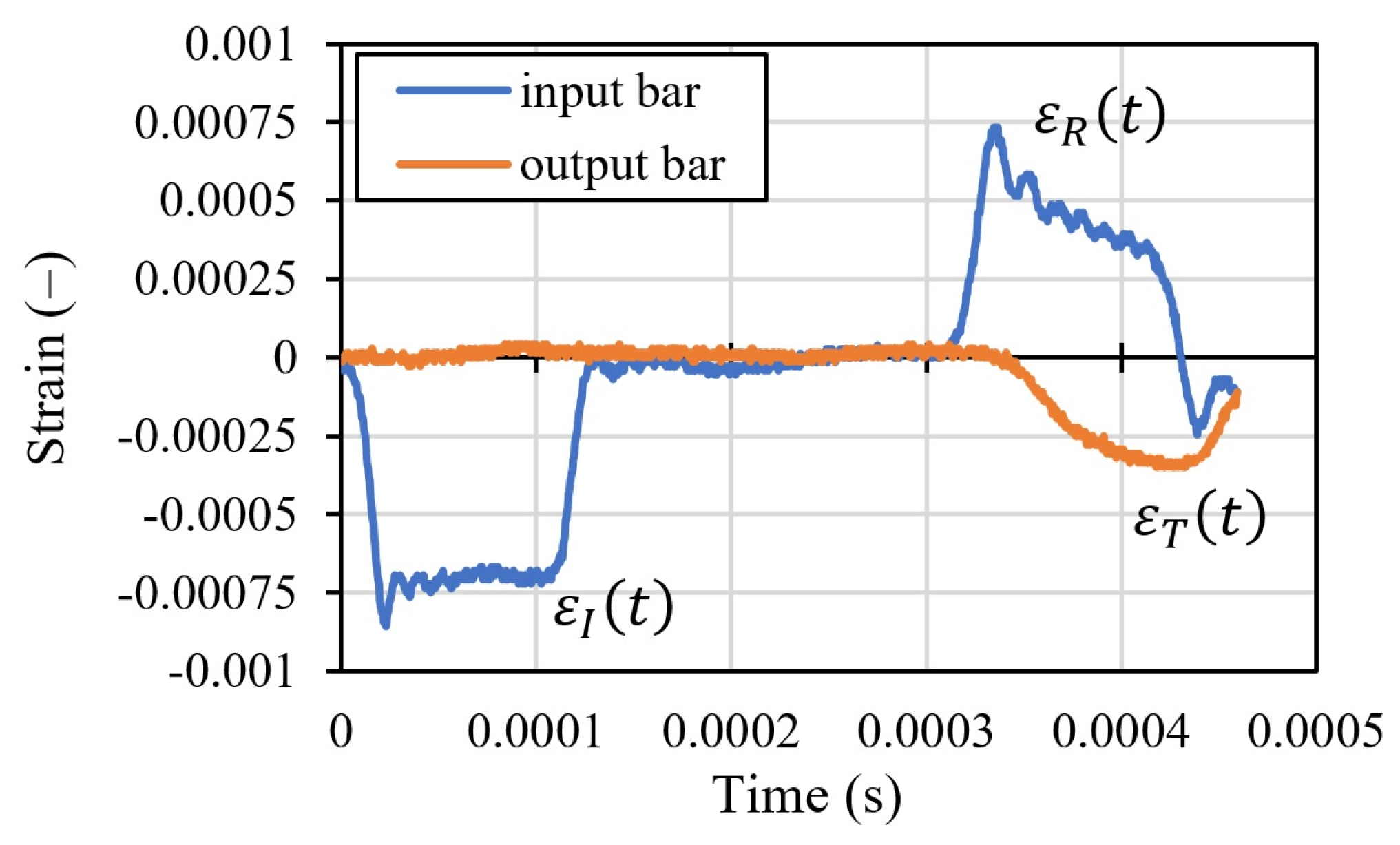
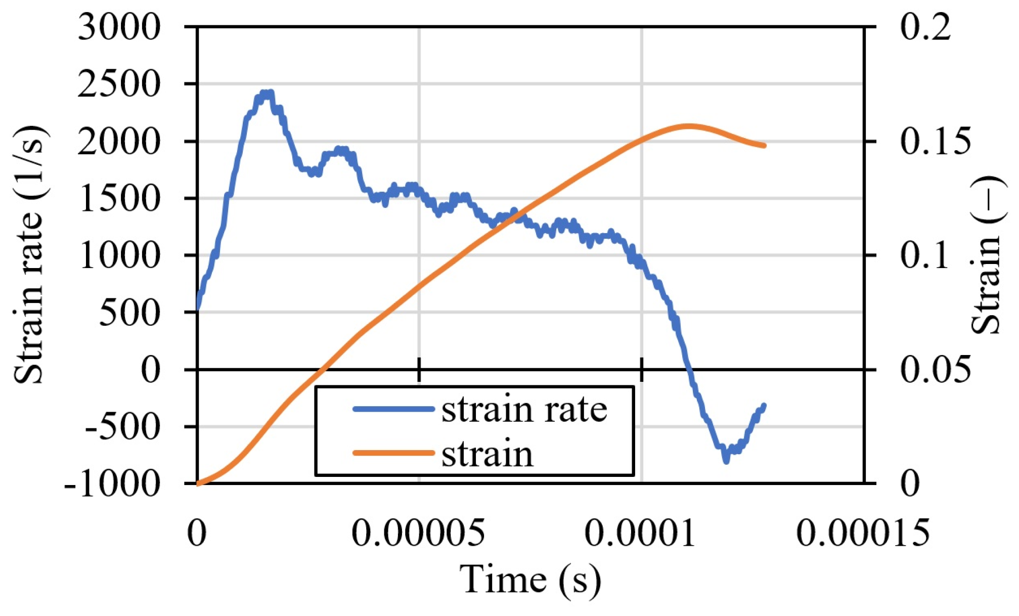
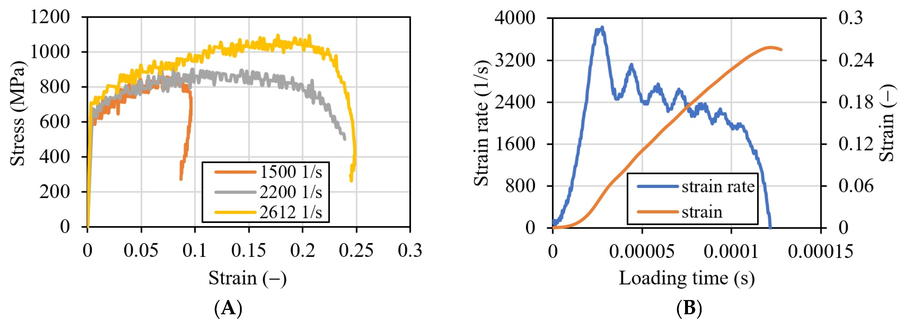
2.3. Dynamic Tests
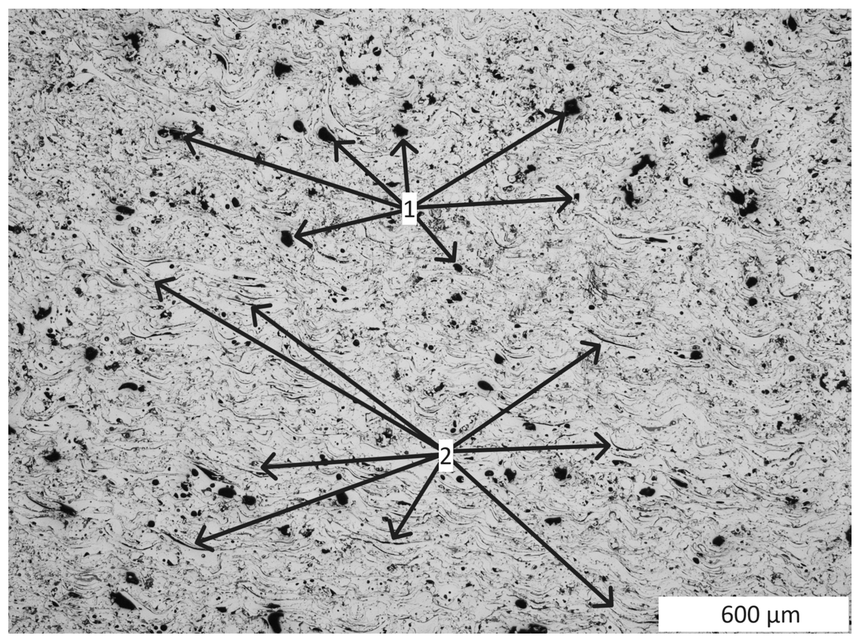
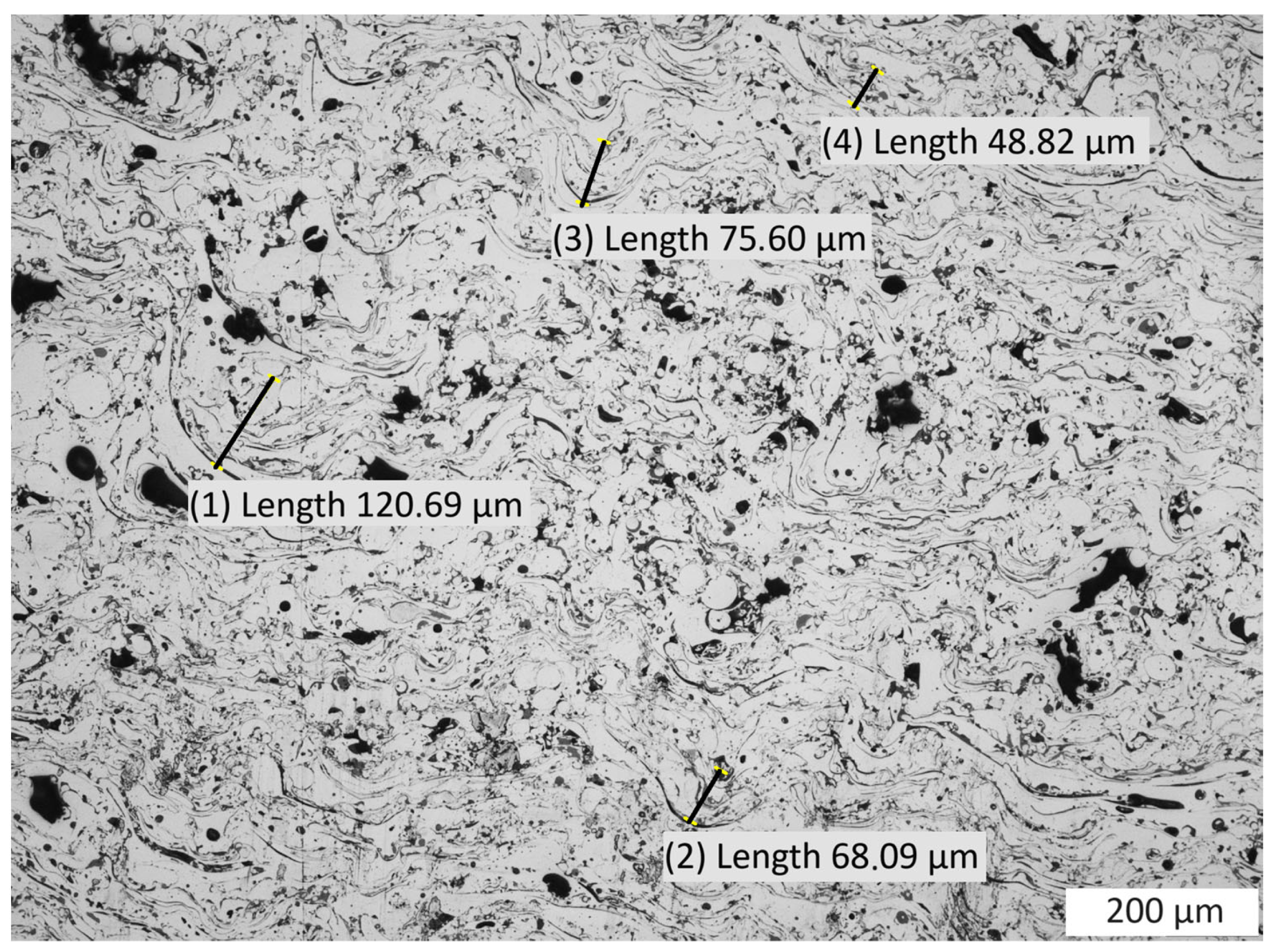
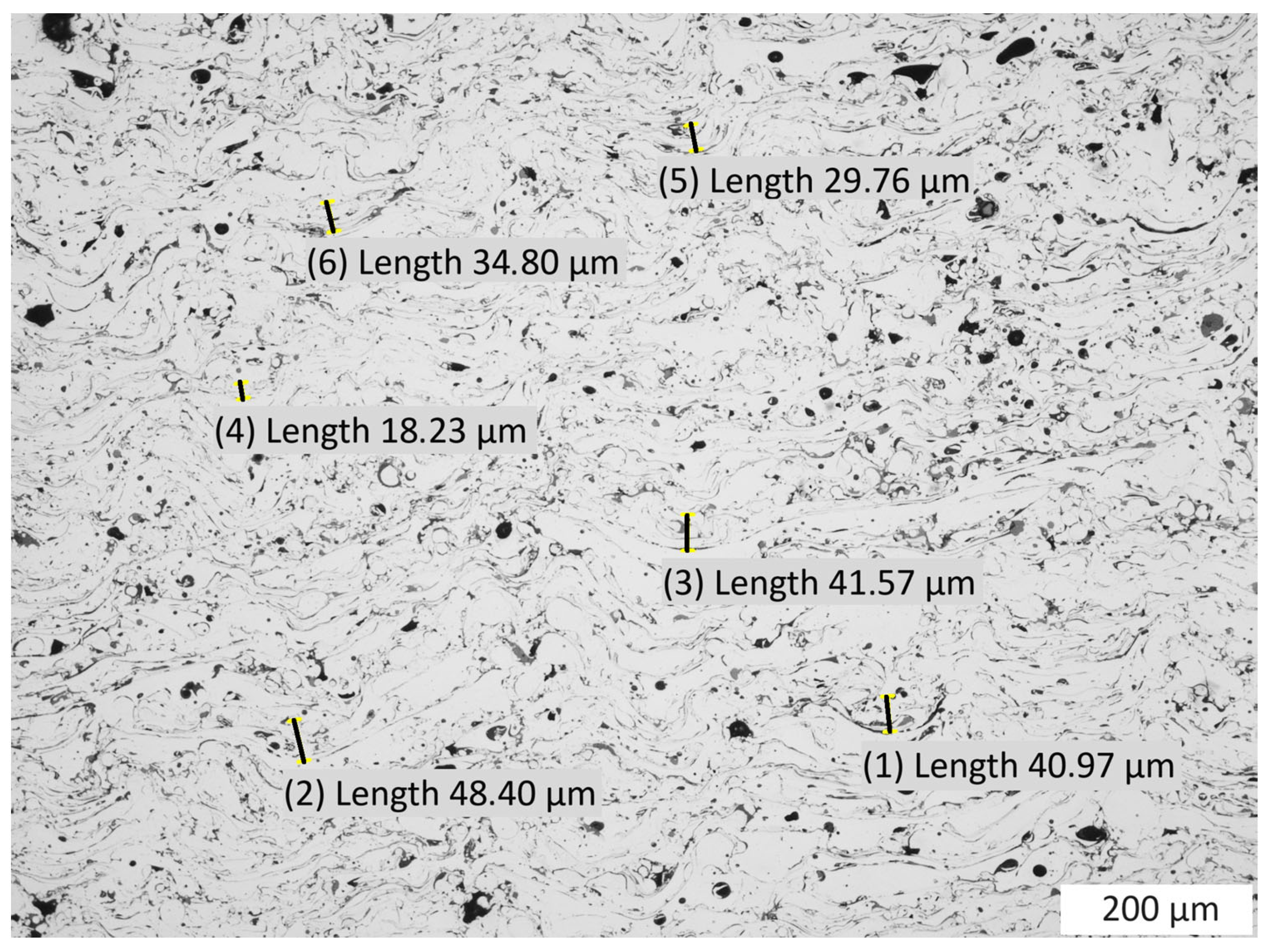
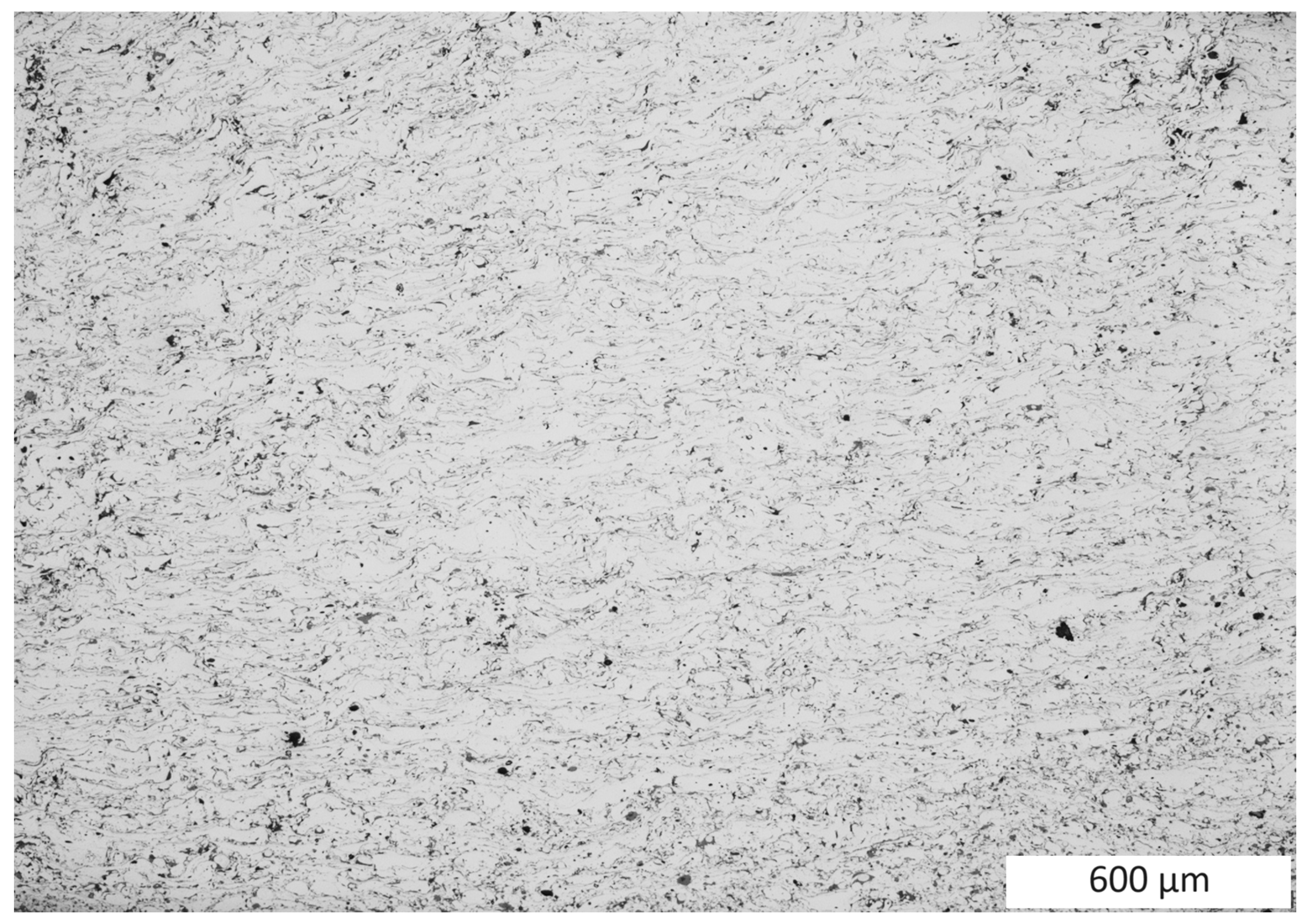
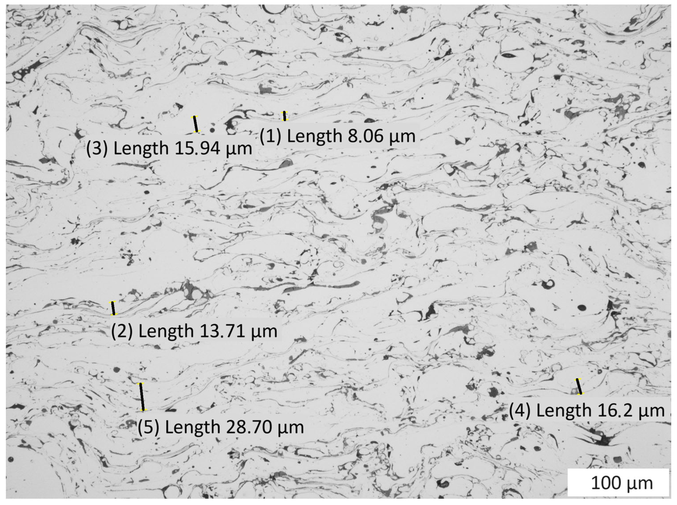
2.4. Evolution of the Microstructure
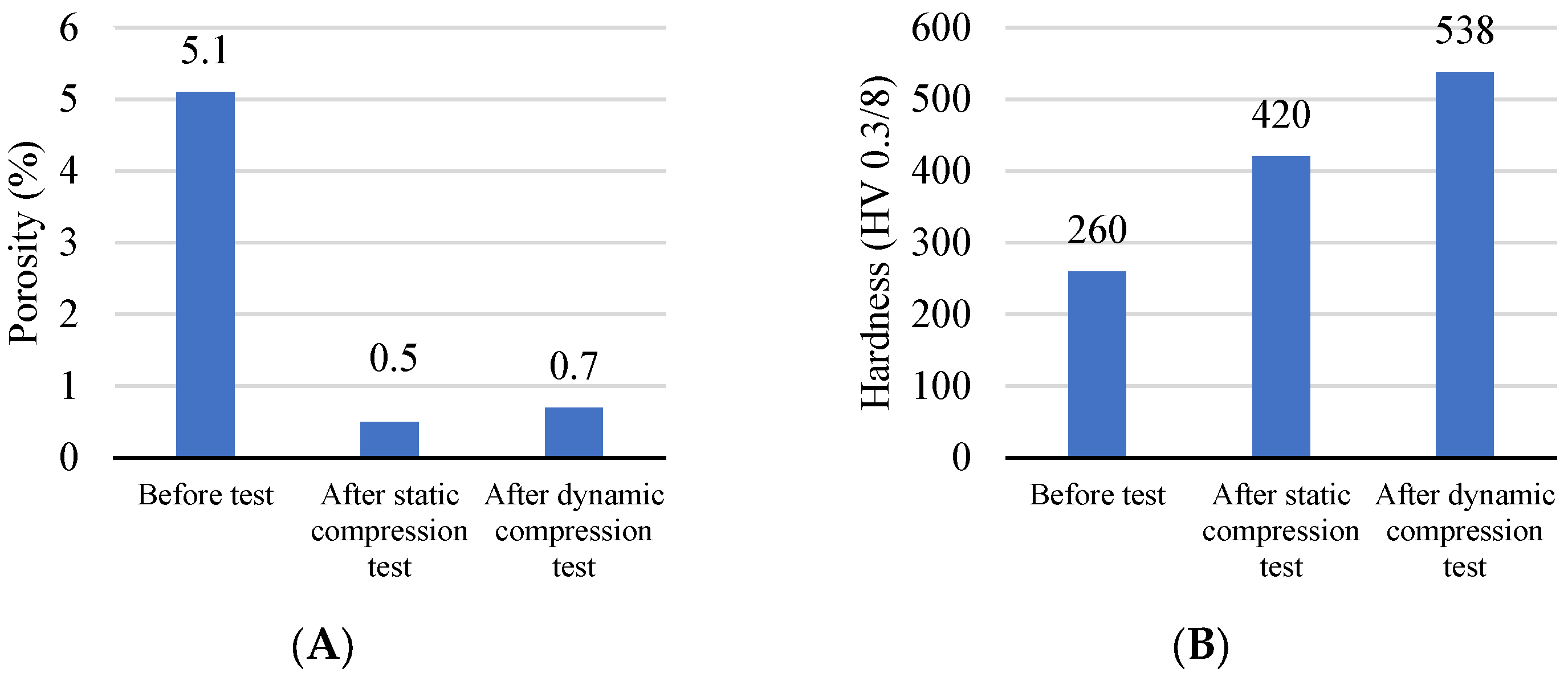
- A decrease in porosity was observed due to both static and dynamic interactions (Figure 14A). The initial porosity of 5.1% decreased to 0.5% (by 90%) in the case of static compression and to 0.7% (by 86%) in the dynamic case.
- An increase in hardness was observed as a result of both static and dynamic interactions (Figure 14B). The initial hardness of 260 HV 0.3/8 increased to 420 HV 0.3/8 (by 62%) in the case of static compression and to 538 HV 0.3/8 (by 107%) in dynamic compression.
3. Conclusions
Author Contributions
Funding
Institutional Review Board Statement
Informed Consent Statement
Data Availability Statement
Conflicts of Interest
References
- Guilemany, J.M.; Cinca, N.; Dosta, S.; Benedetti, A.V. Corrosion behaviour of thermal sprayed nitinol coatings. Corros. Sci. 2009, 51, 171–180. [Google Scholar] [CrossRef]
- Salimi Jazi, H. (Ed.) Advanced Plasma Spray Applications; InTech: London, UK, 2012. [Google Scholar] [CrossRef]
- Tian, H.; Wang, C.; Guo, M.; Tang, Z.; Wei, S.; Xu, B. Study of the frictional-wear performance and abrasion resistance mechanism of a high-speed arc-sprayed FeNiCrAl coating. Surf. Coat. Technol. 2019, 370, 320–330. [Google Scholar] [CrossRef]
- Liang, D.; Zhou, Y.; Liu, X.; Zhou, Q.; Huang, B.; Zhang, E.; Chen, Q.; Shen, J. Wettability and corrosion performance of arc-sprayed Fe-based amorphous coatings. Surf. Coat. Technol. 2022, 433, 128129. [Google Scholar] [CrossRef]
- Chen, W.; Wang, Z.; Xu, G.; Song, W.; Xie, Y.; Zhao, L.; Xia, M.H.; Li, W. Friction and anti-corrosion characteristics of arc sprayed Al+Zn coatings on steel structures prepared in atmospheric environment. J. Mater. Res. Technol. 2021, 15, 6562–6573. [Google Scholar] [CrossRef]
- Espallargas, N. Introduction to thermal spray coatings. In Future Development of Thermal Spray Coatings: Types, Designs, Manufacture and Applications; Elsevier: Amsterdam, The Netherlands, 2015; pp. 1–13. [Google Scholar] [CrossRef]
- GR. BellWall Colmonoy Ltd. B.Sc. Thermal spraying for cost reduction and efficiency. Mater. Des. 1983, 4, 783–790. [Google Scholar] [CrossRef]
- Tucker, R.C., Jr. (Ed.) Introduction to Thermal Spray Technology. In Thermal Spray Technology; ASM Handbook; ASM International: Almere, The Netherlands, 2013; Volume 5A, pp. 3–9. [Google Scholar] [CrossRef]
- Li, C.J.; Ohmori, A. Relationships between the microstructure and properties of thermally sprayed deposits. J. Therm. Spray Technol. 2002, 11, 365–374. [Google Scholar] [CrossRef]
- McCoy, C.A.; Moore, N.W.; Vackel, A. Microstructural Changes to Thermally Sprayed Materials Subjected to Dynamic Compression; Sandia National Lab. (SNL-NM): Albuquerque, NM, USA, 2020. [CrossRef]
- Jankowiak, T. Wykorzystanie Metod Eksperymentalnych i Symulacji Komputerowych do Określania Właściwości Materiałów Przy Dużej Prędkości Deformacji; Wydawnictwo Politechniki Poznańskiej: Poznań, Poland, 2016. [Google Scholar]
- Jankowiak, T.; Rusinek, A.; Łodygowski, T. Validation of the Klepaczko–Malinowski model for friction correction and recommendations on Split Hopkinson Pressure Bar. Finite Elem. Anal. Des. 2011, 47, 1191–1208. [Google Scholar] [CrossRef]
- Miyambo, M.E.; Von Kallon, D.V.; Pandelani, T.; Reinecke, J.D. Review of the development of the split Hopkinson pressure bar. Procedia CIRP 2023, 119, 800–808. [Google Scholar] [CrossRef]
- Field, J.H.; Walley, S.M.; Proud, W.G.; Goldrein, H.T.; Siviour, C.R. Review of experimental techniques for high rate deformation and shock studies. Int. J. Impact Eng. 2004, 30, 725–775. [Google Scholar] [CrossRef]
- Zhong, W.Z.; Rusinek, A.; Jankowiak, T.; Abed, F.; Bernier, B.; Sutter, G. Influence of interfacial friction and specimen configuration in Split Hopkinson Pressure Bar system. Tribol. Int. 2015, 90, 1–14. [Google Scholar] [CrossRef]
- Swain, B.; Chatterjee, S.; Mohapatra, S.S.; Behera, A. Mechanical Properties Evaluation and Parametric Optimization of Atmospheric Plasma Spray NiTi Coating. J. Mater. Eng. Perform. 2022, 31, 8270–8284. [Google Scholar] [CrossRef]
- Serubibi, A.; Hazell, P.J.; Escobedo, J.P.; Wang, H.; Oromiehie, E.; Prusty, G.B.; Phillips, A.W.; St. John, N.A. Fibre-metal laminate structures: High-velocity impact, penetration, and blast loading—A review. Compos. Part A Appl. Sci. Manuf. 2023, 173, 107674. [Google Scholar] [CrossRef]
- ASTM E1920-97; Standard Guide for Metallographic Preparation of Thermal Sprayed Coatings. ASTM: West Conshohocken, PA, USA, 2021.
- ASTM E9-09; Standard Test Methods of Compression Testing of Metallic Materials at Room Temperature. ASTM: West Conshohocken, PA, USA, 2018. [CrossRef]
- ASTM WK65916; New Test Method for Dynamic Compression of Bulk Metallic Materials using a Split Hopkinson Pressure Bar/Kolsky Bar. ASTM: West Conshohocken, PA, USA, 2008.
- Glema, A.; Łodygowski, T.; Sumelka, W. Nowacki’s double shear test in the framework of the anisotropic thermo-elasto-viscoplastic material model. J. Theor. Appl. Mech. 2010, 48, 973–1001. [Google Scholar]


| No. 1 | No. 2 | No. 3 | No. 4 |  | |
| [mm] | 6.06 | 5.97 | 6.00 | 6.08 | |
| [mm] | 2.85 | 2.93 | 2.99 | 3.07 |
Disclaimer/Publisher’s Note: The statements, opinions and data contained in all publications are solely those of the individual author(s) and contributor(s) and not of MDPI and/or the editor(s). MDPI and/or the editor(s) disclaim responsibility for any injury to people or property resulting from any ideas, methods, instructions or products referred to in the content. |
© 2023 by the authors. Licensee MDPI, Basel, Switzerland. This article is an open access article distributed under the terms and conditions of the Creative Commons Attribution (CC BY) license (https://creativecommons.org/licenses/by/4.0/).
Share and Cite
Wypych, A.; Jankowiak, T.; Sumelka, W. Mechanical and Microstructural Properties of Thermally Sprayed Metallic Materials in Compression Tests over a Vast Range of Strain Rates. Materials 2023, 16, 7566. https://doi.org/10.3390/ma16247566
Wypych A, Jankowiak T, Sumelka W. Mechanical and Microstructural Properties of Thermally Sprayed Metallic Materials in Compression Tests over a Vast Range of Strain Rates. Materials. 2023; 16(24):7566. https://doi.org/10.3390/ma16247566
Chicago/Turabian StyleWypych, Artur, Tomasz Jankowiak, and Wojciech Sumelka. 2023. "Mechanical and Microstructural Properties of Thermally Sprayed Metallic Materials in Compression Tests over a Vast Range of Strain Rates" Materials 16, no. 24: 7566. https://doi.org/10.3390/ma16247566