Article

Preparation, Characterization, and Properties of UV-Curable Coating Doped with Nano-SiO2

Department of Materials Chemistry, School of Environmental and Chemical Engineering, Nanchang Hangkong University, Nanchang 330063, China
*
Author to whom correspondence should be addressed.
Materials 2023, 16(24), 7576; https://doi.org/10.3390/ma16247576
Submission received: 10 October 2023 / Revised: 30 November 2023 / Accepted: 2 December 2023 / Published: 9 December 2023
(This article belongs to the Section Polymeric Materials)

Abstract

:
In this study, a hydrophobic, wear-resistant ultraviolet (UV)-curable coating was investigated as an alternative to traditional coatings with low hardness and high susceptibility to scratching. The SiO2 nanoparticles were ground and modified using high-energy ball milling, during which the surface energy of nano-SiO2 particles rapidly increased as their particle size decreased. Different proportions of modified nano-SiO2 particles were added to the coating and cured into a film. The structure of the composite coating was analyzed via infrared spectroscopy, scanning electron microscopy, and X-ray diffraction, which confirmed the successful preparation of the composite coating. The mechanical and optical property tests of the coating were investigated. With a 5% nano-SiO2 content, the hardness of the coating reached 5H, whereas the adhesion was poor (2B), and the flexibility was 1. The overall comprehensive performance of the coating was best when the addition amount was 3%. The coating exhibited good hardness, flexibility, and adhesion. The hardness of the coating reached 4H, the adhesion was 4B, the flexibility was 5, the coating haze was 12.38 HZ, and the contact angle was 118°.

1. Introduction

UV-curable coatings are generally composed of UV-curable resins, active diluents (monomers), photoinitiators, and small amounts of additives [1,2,3,4], typically requiring short periods of UV irradiation to affect curing [5]. With the development of science and technology, plastics have become an indispensable material in the production of flexible products; however, their application in the coatings field is limited, owing to their low surface hardness and poor wear resistance [6]. Therefore, to improve these properties, the hardening method of UV-curable coatings on the surface of plastics has been considered because of its low cost, convenience, and simplicity [7,8,9,10]. In some cases, pure organic coatings have good compatibility, adhesion, and flexibility with the substrate after curing, owing to their molecular structural characteristics [11,12,13,14]. However, owing to their inherent characteristics, organic coatings often exhibit high shrinkage [15], poor wear resistance [16], and low hardness [17] after curing. Inorganic films mainly comprise inorganic oxide and non-oxide materials [18,19], which exist in crystalline and amorphous forms and are mainly deposited on plastic substrates using PVD [20] and CVD [21] technology. Plastic deformation or softening is often caused by the high temperature of the deposited plastic substrate [22]. In addition, the bonding between inorganic films and plastic substrates is poor, and they easily peel off [23,24]. Organic/inorganic hybrid films attempt to integrate the advantages of the aforementioned films and overcome their shortcomings, which is a current research hotspot. Currently, most transparent hard organic/inorganic film materials are based on polysiloxanes or other inorganic polymers. This hybrid material has an O–M–O (M = Si, Ti, Al, Zr, or other metal ions) network structure as the basic skeleton, and its adhesion to plastic substrates is improved by adding organic components [25,26,27]. After more than ten years of development, the synthesis methods for hybrid materials have continuously improved. Si-containing organic/inorganic nanohybrid materials are an important class of hybrid materials. These materials are mainly synthesized using methods such as sol–gel [28], in situ polymerization [29], intercalation [30], self-assembly [31], and blending [32].
The small particle size, insufficient atomic coordination, large specific surface area, and high surface energy of nano-SiO2 particles contribute to their high activity, instability, and easy agglomeration [33,34]. Appropriate physical or chemical methods [35,36,37,38] must be adopted to obtain nano-SiO2 particles with good dispersion, a small particle size, and narrow particle size distribution and to enhance their compatibility with organic systems. High-energy ball milling is a surface modification technology that significantly reduces reaction activation energy, refines grains, and improves the powder activity and uniformity of particle distribution. Furthermore, the method improves the combination of the interface between the SiO2 and the resin, promotes the diffusion of solid ions, and induces low-temperature chemical reactions, thus improving the compactness and electrical, thermal, and other material properties. This method is also an efficient material preparation technology.
The high-energy ball-milling method is a better method for the preparation of nanoparticles than the blending method and ultrasonic method in our experiments. To achieve high hydrophobicity and scratch resistance, inorganic and organic hybrid UV-curable coatings containing nano-SiO2 have become a research subject. In our previous study, inorganic and organic hybrid UV-curable coatings for different nano-metal oxides were investigated [39,40]. In this paper, the high-energy ball-milling method was used to crush and grind nanoparticles, which were then modified using a dispersant. The modified nano-SiO2 particles were added to a UV-coating system to prepare an organic–inorganic composite coating doped with nano-SiO2 particles. The experimental formula was optimized by adjusting the type and quantity of monomers and the proportion of resin. The mechanical properties, such as wear resistance, hardness, and adhesion, of the composite coating with different nano-SiO2 contents were explored. The particle size of the nano-SiO2 particles was measured and analyzed using a nanoparticle size meter, and their dispersion in the coating was examined via scanning electron microscopy (SEM). The coating structure was analyzed via Fourier transform infrared spectrometry (FTIR) and X-ray diffraction. The thermal stability of the coating with different SiO2 contents was tested using a thermogravimetric analyzer, while its hydrophobicity was tested using a contact angle meter.

2. Materials and Methods

2.1. Chemicals and Reagents

Nano-SiO2 powder (99.99%) was purchased from Aladdin Chemical Co., Ltd. (Shanghai, China). Afcona 4071 (44–46 wt%) was purchased from Evkona Additives Co., Ltd. (Haimeng, China). Ethyl acetate, toluene, and n-butyl acetate were purchased from Guangzhou Xinguan Chemical Co., Ltd. (Guangzhou, China). Polyurethane acrylate (B-619 W) was purchased from Guangzhou Boxing Chemical Co., Ltd. (Guangzhou, China). The monomers hexanedioldiacrylate (HDDA) and acrylated dipentaerythritol (DPHA) were purchased from Taiwan Changxing Chemical Co., Ltd. (Guangzhou, China). Photoinitiator (184) was purchased from Tianjin JiuriNew Materials Co., Ltd. (Tianjin, China). PET film was purchased from Shenzhen Puti Technology Co., Ltd. (Shenzhen, China).

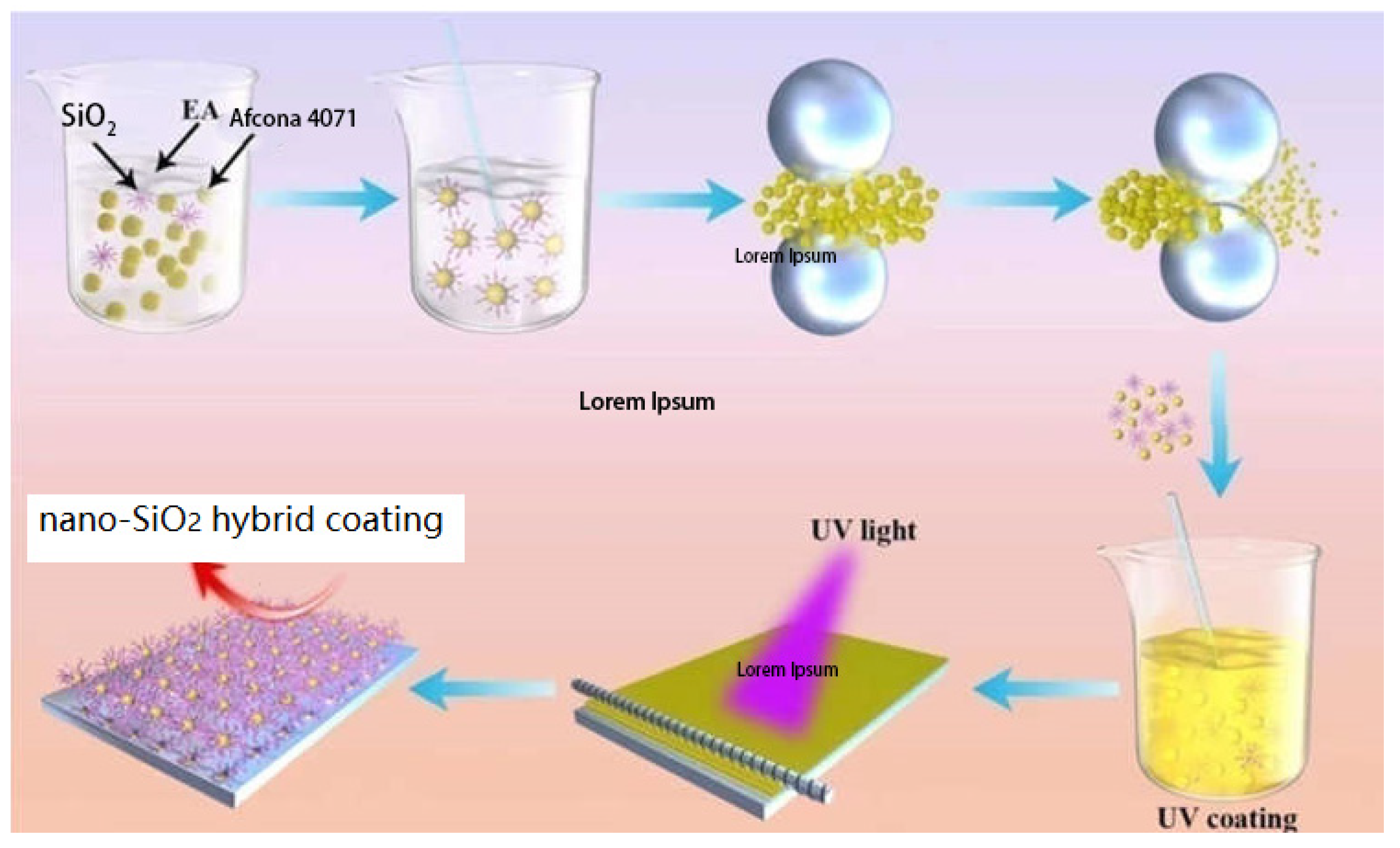
2.2. Modification of Nano-SiO2 via High-Energy Ball Milling

Dispersions were prepared from the as-purchased SiO2, the polyurethane dispersant Afcona 4071 (a 44–46% solid solution), and ethyl acetate as solvent. The dispersions were designed to have a final solid content of 50%, and the dispersions contained 0 (the control, without ethyl acetate addition), 1%, 2%, 3%, 4%, and 5% by weight of SiO2 powder, with re-adjustment of total solid content via ethyl acetate addition. In turn, each dispersion was transferred to the feed chamber of a horizontal bead mill loaded with 0.1 mm zirconia (140 mL) beads and milled for 1 h at a speed of 3800 rpm. The volume of the ball-mill container was 200 mL. The ratios of sample:balls:container were x:140 mL:200 mL. The sample was cyclically injected into the ball-mill container via a pump. The product dispersions were collected and used in the coating formulations. The preparation process of composite coatings is presented in Scheme 1.

2.3. Preparation of Composite Coatings

B-619W was used as the main resin, HDDA and DPHA were used as the active diluents, 184 was used as the photoinitiator, and ethyl acetate was used as the solvent. The resin, monomers, and photoinitiator were weighed in appropriate proportions and mixed until an even consistency was obtained. Subsequently, 1–5% of nano-SiO2 dispersion was added, following which the evenly mixed UV-curable coating was diluted until an optimal coating consistency was obtained. A wire rod was used to spread the coating onto the 18.8 mm thick PET substrate, which was then baked in an oven for 1 min at 80 °C. The dried coating was cured in a UV-curing machine prior to the evaluation of its performance. An RX300-1 UV curing machine (Ergu Photoelectric Co., Ltd., Dongguan, China) was used. The main wavelength of the mercury light was 365 nm. The irradiation distance was about 15 cm. The curing time of the sample was less than 60 s at room temperature.

2.4. Characterization

2.4.1. FTIR Spectra

The cured film was peeled off from the PET substrate and ground into a powder. FTIR spectra of the sample were generated via an American Nicolet Magna380 infrared spectrometer (Waltham, MA, USA), using the KBr compression method, with a resolution of 4 cm−1 and a limited scanning wavelength range of 400–4000 cm−1. The absorption of the coating was detected in this band.

2.4.2. XRD Spectra

The cured film was peeled off from the glass slide, ground into a powder, and analyzed using a D8 Advance (Bruker, Saarbrücken, SAAR, Germany) X-ray powder diffractometer. Bruker D8 Advance diffractometer was operated at 40 kV and 40 mA with a CuKα radiation source in reflection mode using a two-circle goniometer in a Bragg–Brentano arrangement. The scanning range was 20~70°, and the scanning speed was 5°/min.

2.4.3. Scanning Electron Microscope (SEM) Analysis

A small amount of the sample was uniformly coated on the silicon wafer with a rubber-tipped dropper and cured into a film. Prior to electron imaging, samples were coated with 10 nm of gold using a Leica ACE600 sputter coater (Leica Microsystems Inc., Deerfield, IL, USA). The sample was put into a NovaSEM450 field emission scanning electron microscope (FEI Company, Hillsboro, OR, USA) for imaging.

2.4.4. Thermogravimetric Analysis

A TG-209 thermogravimetric (Netzsch, Selb, BW, Germany) analyzer was used to weigh the quantitatively dried samples, which were placed into a crucible for testing in a nitrogen atmosphere. The test temperature range was 0~800 °C, the heating rate was 10 °C/min, and the air flow rate was 100 mL/min. The data were recorded every 0.5 s.

2.4.5. Mechanical Property Tests

The pencil hardness test was conducted according to the ASTM D3363-05 standard [41]. The adhesion refers to ASTMD3002 (0B–5B). Portable pencil hardness tester (QHQ-A, Dongguan Guohua Experimental Instrument Co., Ltd., Dongguan, China) was used to test the hardness of the coating. A pencil was scratched five times on the film under a certain applied force (500 g or 750 g), and the hardness of the paint film was determined via the pencil hardness that produced no scratch. A paint film elasticity tester (QTX, Tianjin Hongjuli Experimental Instrument Factory, Tianjin, China) was used to test the flexibility of the coating according to the GB/T 1731-1993 standard [42].

2.4.6. Haze Tests

Transmittance haze tester (JZ-WGT-S) was used. Haze means the ratio of the scattered light flux to the transmitted light flux that passes through the specimen and deviates from the direction of the incident light. Haze is an important parameter for the optical transparency of transparent or semi-transparent coatings. After the calibration of the machine, the cured film was placed in a haze meter, and haze testing was performed on it. Each coating was measured three times, taking the average value as the final haze, usually expressed in Hz.

2.4.7. Wear Resistance Test

Steel velvet wear resistance testing machine (339-GSR, Shenzhen, China) was used to test the wear resistance properties. The cut steel wool was wrapped around the friction head. Then, the diaphragm was fixed in the friction area as flat as possible to prevent it from loosening during friction. Various loads, such as 500 g and 1000 g, and the frequency of friction cycles were applied. The friction head was rubbed back and forth. After the friction test, the surface of the diaphragm was observed.

2.4.8. The Contact Angle Test

A water droplet angle tester and the computer connected to it were turned on, and 1–2 drops were added on the coating with 1 μL water droplets and, after being dropped, were connected to the water droplet angle through the rising sample stage. After clicking on the freeze button, a measuring ruler tangent to the edge of the droplet was made by clicking on the shortcut button, and then, the value of the contact angle was recorded.

2.4.9. Particle Size Analysis

Zhenli Optical Laser Particle Sizer (Truth Optical Instrument Co., Ltd., Zhuhai, China) was used. A certain amount of nanodispersion was sucked into a beaker using a pipette, diluting it 20–30 times with toluene, stirring evenly. Then, a pipette was used to absorb the diluted dispersion and add it to a colorimetric dish. Afterward, the dispersion on the colorimetric dish was placed into a particle size analyzer to test the particle size. Each sample was measured in 3 groups, with each group measured 10 times. D10, D50, and D90 were used for analyzing particle sizes. D10 represents the particle size of a sample when the cumulative particle size distribution reaches 10%. This means that 10% of the particles are smaller than it. D50 represents the particle size of a sample when the cumulative particle size distribution percentage reaches 50%. This means particles larger than it accounted for 50%, while smaller particles also accounted for 50%. D50 is often used to represent the average particle size of powders. D90 represents the particle size of a sample when the cumulative particle size distribution reaches 90%. This means that 90% of the particles are smaller than it.

3. Results

3.1. Effect of Different Afcona 4071 Additions on the Particle Size of Nano-SiO2

Figure 1a,b show the effect of different concentrations of dispersant on the size of nano-SiO2 particles and their particle size distribution when Afcona 4071 was added, respectively. The used Afcona 4071:SiO2 weight ratios are 0:100, 10:90, 20:80, 30:70, 40:60, and 50:50 wt%. As shown in Figure 1a, the initial average particle size of nano-SiO2 was 579 nm. After 1 h of high-speed dispersion, the average particle sizes of the SiO2 were 126, 97, 76, 64, and 82 nm for different SiO2 contents. When only a small amount of dispersant is added, the organic groups are not sufficient to coat the nano-SiO2 particles completely. Dispersion is, thus, hindered by an increase in agglomeration caused by covalent bonds and/or van der Waals forces. Our findings demonstrated that an optimal dispersion was achieved with 40% Afcona 4071, with the size of nano-SiO2 particles at their smallest. As shown in Figure 1b, after grinding and dispersion, the average particle size was 64 nm, with a narrow particle size distribution and uniform particle size.

3.2. Coating Formulation Optimization and Coating Performance Test

(1)
Effect of monomer type and dosage on coating properties
In Table 1, the main resin (B-619W) and photoinitiator 184 were kept at 80% and 5%, respectively. The HDDA:DPHA ratios were 1:0, 1:1, 1:2, 2:1, and 0:1. Coating preparation, application, and testing were carried out according to the methods described in Section 2.3. Coating properties, as listed in Table 2, were obtained at a coating thickness of 4 μm. These properties indicate that an increase in the proportion of DPHA improved the hardness of the coating, whereas the adhesion and flexibility of the coating decreased. With increasing proportions of HDDA, the adhesion and flexibility of the coating improved, whereas the hardness of the coating was low. The overall performance of the coating was optimal at a 1:1 ratio of HDDA:DPHA, with an adhesion of 4B, a flexibility of 6, and a hardness of 2H/750 g.
(2)
Effect of different resin ratios on coating properties
In Table 3, the ratio of the monomers (HDDA:DPHA) was maintained at 1:1, the proportion of the photoinitiator was maintained at 5%, and the proportions of the resin were varied. Coating preparation, application, and testing were carried out according to the methods described in Section 2.3. The coating properties, as listed in Table 4, were obtained at a coating thickness of 4 μm. The change in the coating performance was nonlinear. An increase in resin content led to a higher degree of crosslinking, which resulted in the improved hardness and adhesion of the coating. Since B-619W is a hexahedral resin, the coating hardness is expected to decrease with increased proportions of resin. Our findings confirmed good adhesion and flexibility, as well as a hardness that reached 2H/750 g when the proportion of resin was 75%.

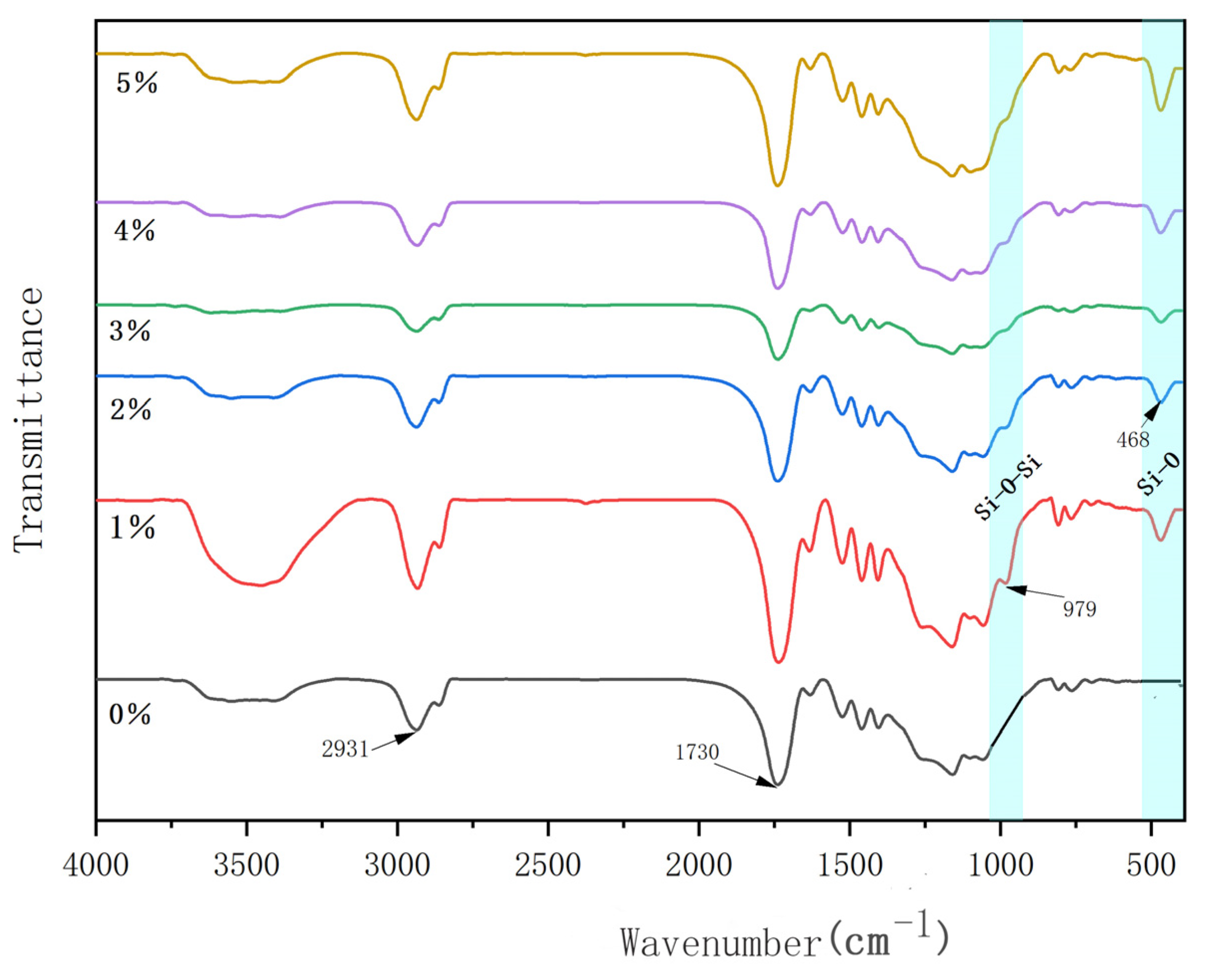
3.3. IR Testing of Composite Coatings

Figure 2 shows the infrared spectra of coatings that contain varying contents of nano-SiO2, i.e., 0%, 1%, 2%, 3%, 4%, and 5%. A characteristic vibration peak of C=O is seen at 1730 cm−1. The wide band centered around 3500 cm−1 is attributed to the O–H stretching vibration. For the sample with 1% nano-SiO2 content, it could contain some residual H2O. The absorption peak at 2931 cm−1 may either be attributed to the characteristic absorption peak of –CH2 present in the mixture or to the O–H bending vibration caused by an incomplete group reaction. The spectra of the coatings that contained SiO2 not only retained the characteristic peak seen in the coating without SiO2 but also showed the emergence of an additional absorption peak at 468 cm−1, caused by the bending vibration of the Si–O bond. The absorption peak at 979 cm−1 can be attributed to the antisymmetric stretching vibration of the Si–O–Si bonds [43]. This proves that the composite coating formed a Si–O–Si network structure.

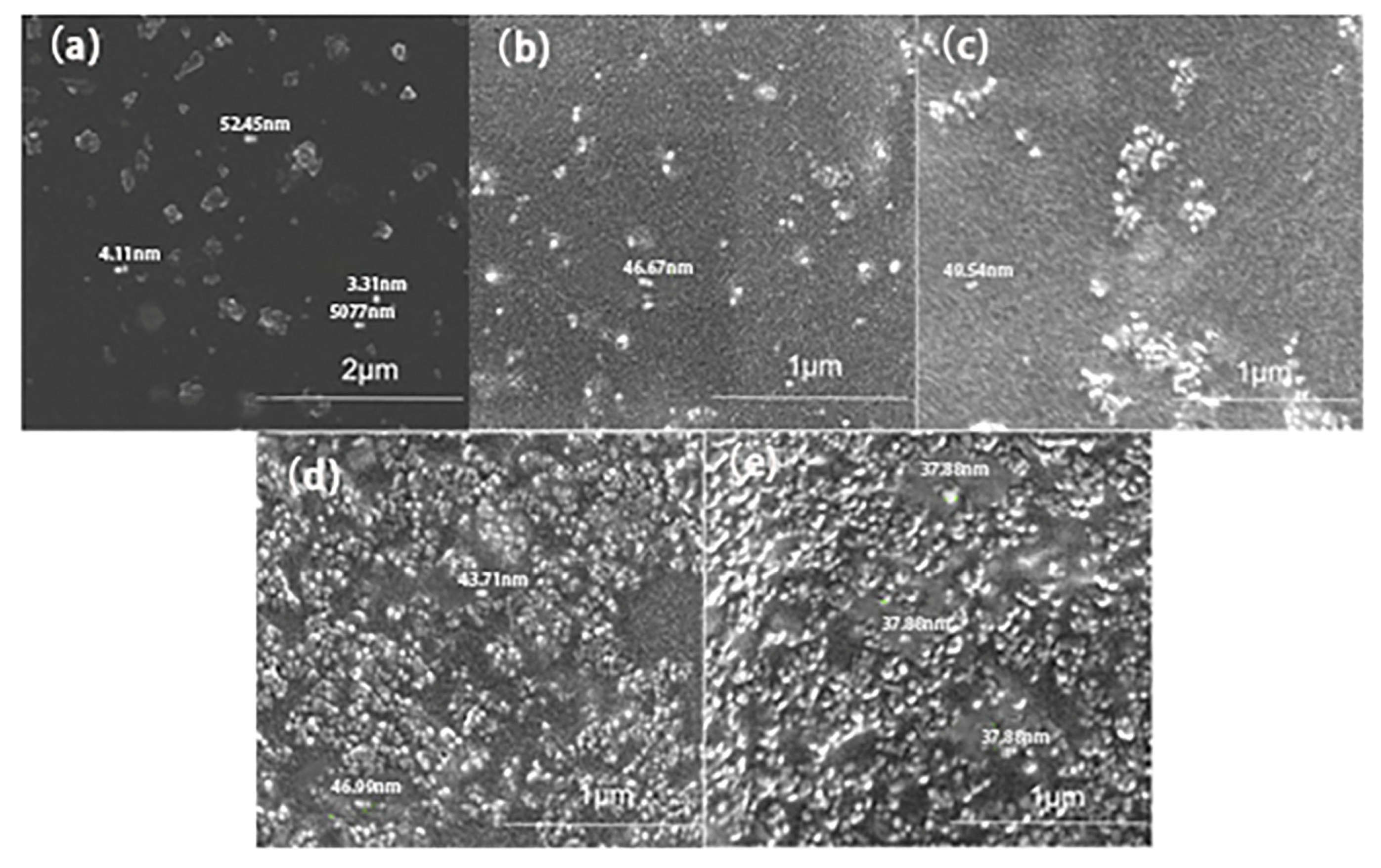
3.4. SEM Analysis of Composite Coatings

Figure 3 shows the structure and surface morphology of the coating with 1%, 2%, 3%, 4%, and 5% amounts of nano-SiO2 particles. It is clear from Figure 3 that spot-like particles of SiO2 were formed. The particle sizes were between 20 and 80 nm, all less than 100 nm. The decrease in distance between particles increases with the number of particles. When the amount of nano-SiO2 was 5%, a slight agglomeration was observed in the coating, which may be due to the increase in the number of nano-SiO2 particles, the corresponding increase in the viscosity of the system, the decrease in the distance between the SiO2 nanoparticles, and the increase in interactions.

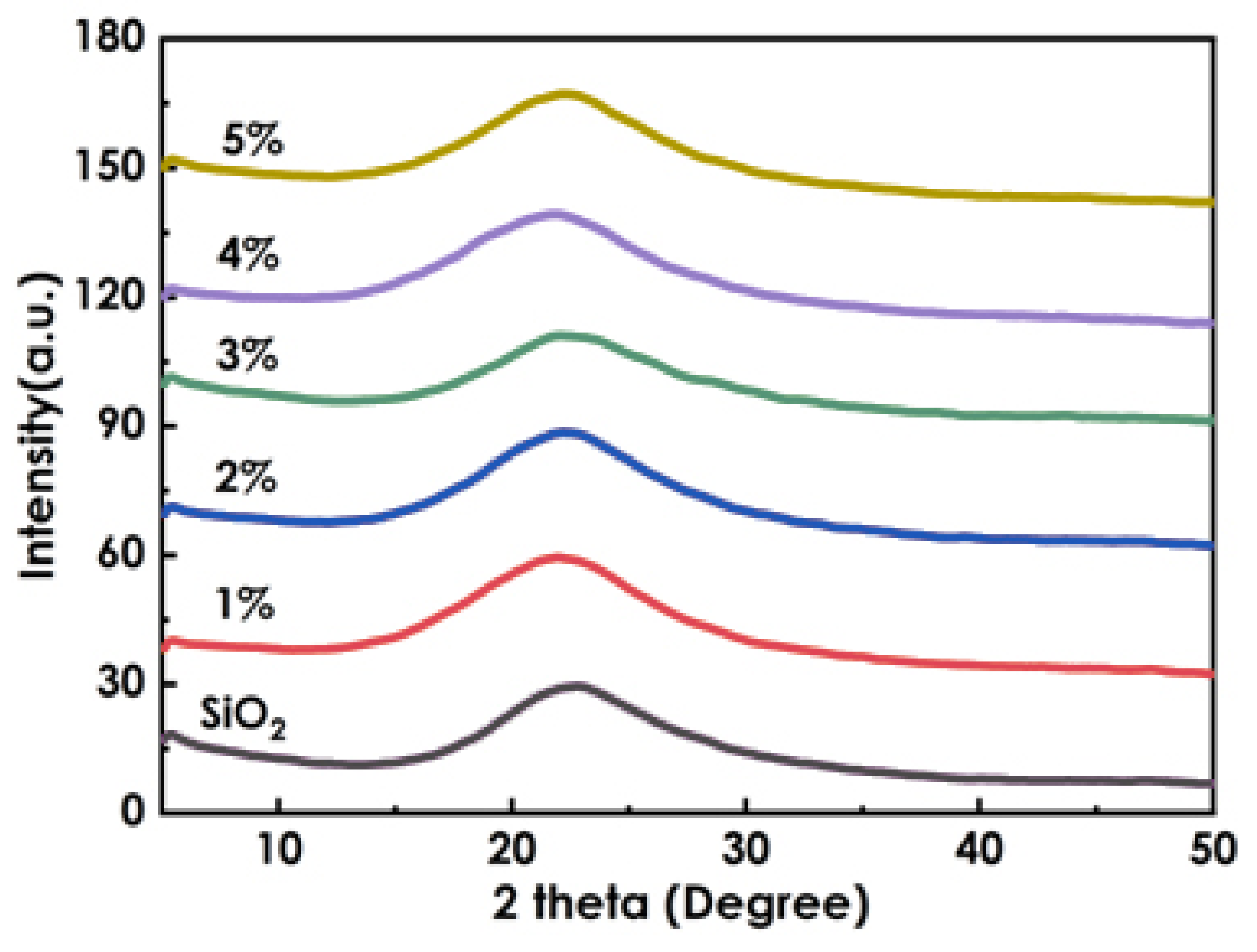
3.5. XRD Analysis of Composite Coatings

Figure 4 shows the standard spectrum of SiO2 and the spectra for different added amounts. The microstructures of the untreated SiO2 and composite coatings were compared using XRD. As shown in Figure 4, no sharp test peak was observed near 22.32°, whereas a steamed bread peak with a width close to the height was observed. This observation indicates extremely low crystallinity and an almost amorphous microstructure. The absorption peak of SiO2 in the composite coating shifts slightly to the left. This offset may have been caused by residual stress within the material. Compared with the characteristic peak standard card of SiO2 (JCPDS29 0085), SiO2 mainly existed in an amorphous state before and after treatment.

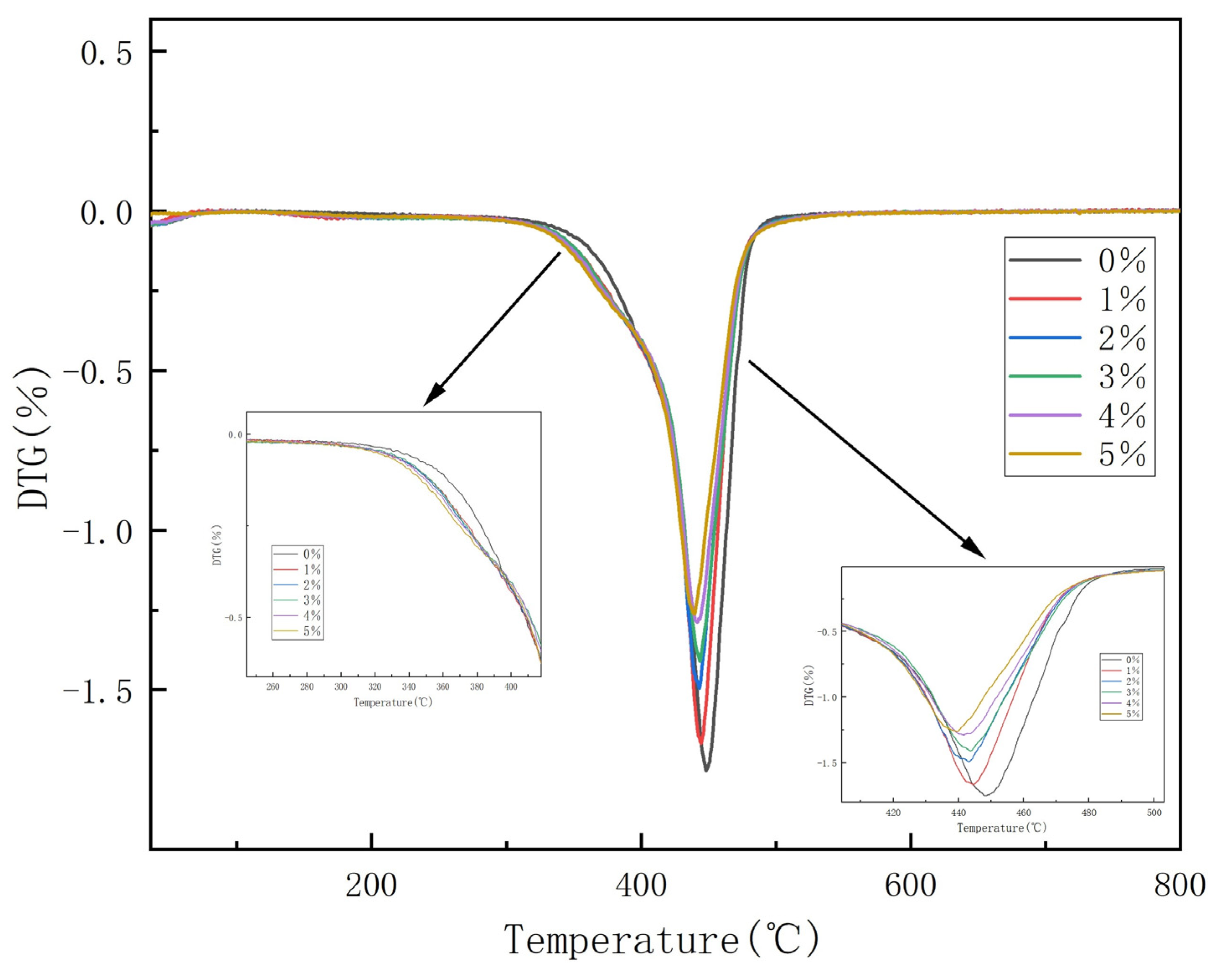
3.6. Thermogravimetric Analysis of Composite Coatings

Figure 5 and Figure 6 show the TG and DTG graphs, respectively, for the coatings with varying SiO2 contents. As shown in Figure 5, the decomposition process of the coating at 0–800 °C can be divided into two stages, namely, 0–98 °C and 98–480 °C. According to Figure 6, the maximum weight loss peak of the coating was at approximately 400 °C. The first stage of weight loss was primarily due to the volatilization of residual solvents and free water in the system, with a weight loss rate of approximately 2%. The second stage of weight loss was due to the decomposition of organic matter, such as the resin and monomers, after UV curing. The figures indicate that the thermal stability of the coatings that contained 5% SiO2 is superior to that of the other coatings. The superior stability can be ascribed to the Si–O–Si structure of the coatings, which is expected to hinder the decomposition of the polymer. With the increase in nano-SiO2, the thermal stability is increased. This may be attributable to the interrelation between inorganic and organic elements.

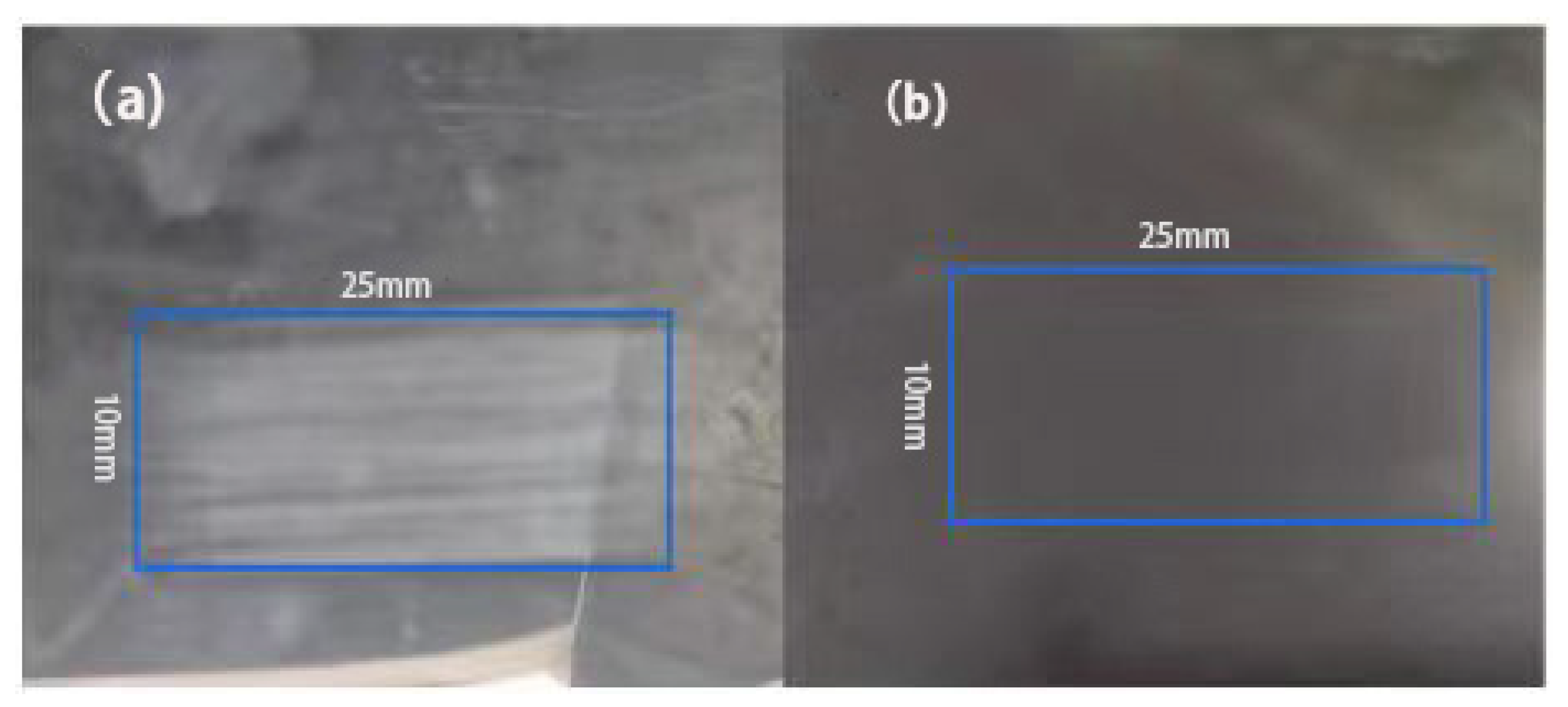
3.7. Wear Resistance Test of Composite Coatings

Figure 7a illustrates the appearance of the coating film without nano-SiO2 powder after 500 grinding cycles under a load of 1 kg, indicating serious wear damage. Figure 7b illustrates the appearance of the coating film with the addition of 3% nano-SiO2 powder after 2000 grinding cycles under a 1 kg load. This illustration clearly indicates an absence of visible scratches, only slight damage, and an intact substrate. This comparison demonstrates that the addition of nano-SiO2 greatly improved the wear resistance of the coating.

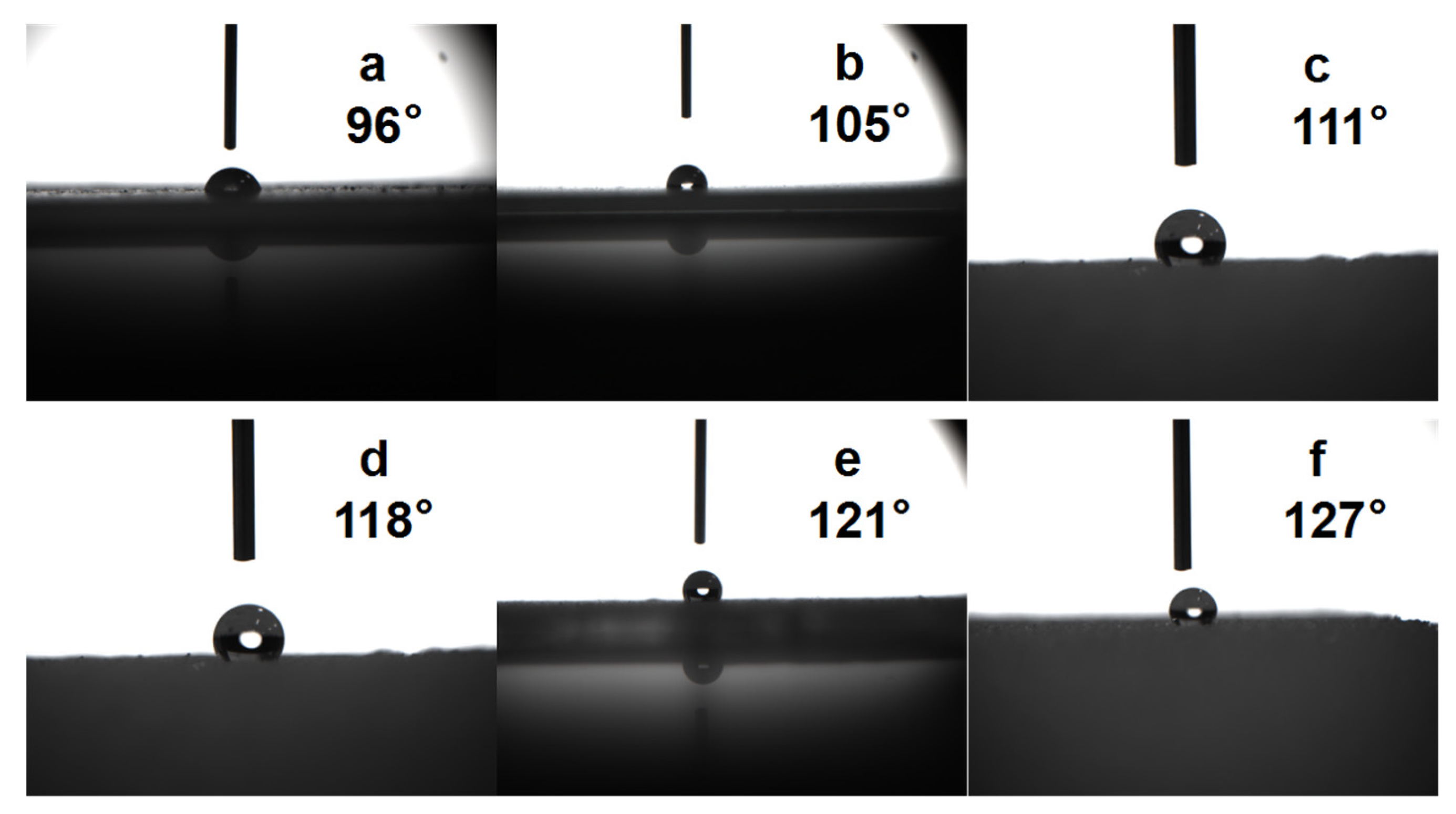
3.8. Contact Angle Test of Composite Coatings

The contact angle of water on a material is an important parameter of the wettability of hydrophobic surfaces. Figure 8 and Figure 9 illustrate the effect of the nano-SiO2 content on the contact angle. The static contact angle of the measured surface of the organic coating devoid of nano-SiO2 was 96°, whereas the addition of nano-SiO2 at amounts of 1, 2, 3, 4 and 5% resulted in an increase in the static contact angles of the coatings to 105°, 111°, 118°, 121°, and 127°, respectively. Our findings demonstrate that the addition of nano-SiO2 particles provides excellent hydrophobicity to the coatings. This increase in contact angles is attributable to an increased roughness of the coating surface caused by an increased nano-SiO2 content. According to the wettability theory, the actual contact area between water droplets and the treated rough surface changes, leading to an increase in the solid–gas contact surface that results in an increase in the contact angle.

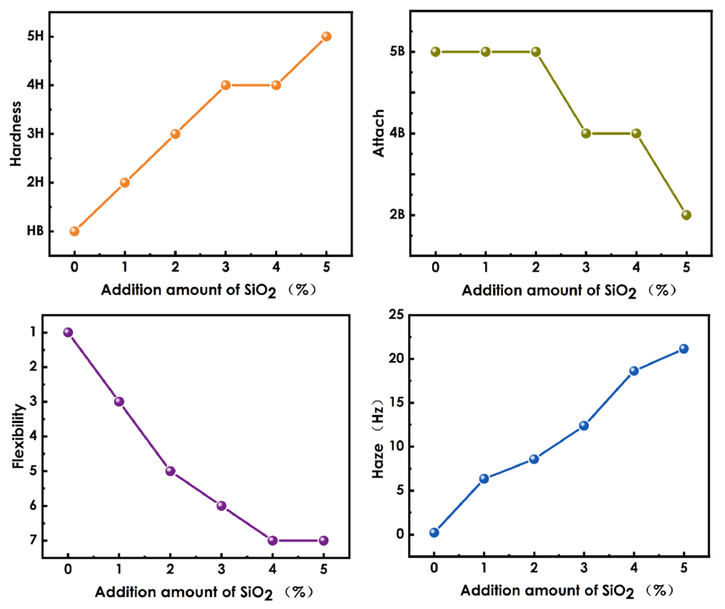
3.9. Evaluation of Haze and Mechanical Properties of Composite Coatings

A total of 75 parts of B-619W, 10 parts of HDDA, 10 parts of DPHA, and 5 parts of 184 were weighed and mixed to an even consistency. Subsequently, 1–5% SiO2 and an appropriate amount of Afcona 4071 were added and mixed to achieve an even consistency. The mixture was ground for 30 min in a sand mill. The ground coating was diluted to a 40% solid content and then coated onto a 1.88 mm thick pet substrate using a 20 # wire rod. A performance test was then conducted on the cured film coating. As shown in Figure 10, an increase in SiO2 content improved the hardness of the film coatings significantly, with a corresponding increase in haze, whereas the flexibility and adhesion of the coatings decreased. At a nano-SiO2 content of 5%, the hardness of the coating reached 5H; however, the adhesion of the film was only 2B, and the flexibility was 1. The overall performance of the coating was optimal at a nano-SiO2 content of 3%. With this nano-SiO2 content, the coating exhibited good hardness, flexibility, and adhesion. The hardness reached 4H, the adhesion was 4B, the flexibility was 6, and the coating haze was 12.38 HZ.

4. Conclusions

In this study, nano-SiO2 particles were modified via high-energy ball milling and subsequently dispersed in ethyl acetate. The nano-SiO2 dispersions, containing nano-SiO2 particles with an average size of 64 nm, were cured in a UV-coating system. FTIR and XRD were used to evaluate the structure of the composite coatings. SEM analyses indicated that the modified SiO2 particles were evenly dispersed but exhibited light agglomeration throughout the coatings. Assessments of the mechanical and optical properties and thermal stabilities demonstrated that a 3% nano-SiO2 content provided an optimal composite coating, with hardness, adhesion, and flexibility reaching 4H, 4B, and 6. Under a load of 1 kg, which was applied over 2000 times, the coating haze reached 12.38 HZ, and the contact angle was 118°. The thermal stability of the composite coating was superior to that of the organic coatings. These findings confirm the successful preparation of a composite coating with excellent hardness and wear resistance, as well as a high contact angle. It has potential applications as a protective, hydrophobic, and wear-resistant coating.

Author Contributions

Conceptualization, T.C. and Z.W.; methodology, T.C.; software, T.C.; validation, T.C., Z.W. and R.Z.; formal analysis, T.C.; investigation, Z.W.; resources, Z.W.; data curation, Z.W.; writing—original draft preparation, T.C. and Z.W.; writing—review and editing, R.Z.; visualization, R.Z.; supervision, R.Z.; project administration, R.Z.; funding acquisition, R.Z. All authors have read and agreed to the published version of the manuscript.

Funding

This research was funded by the National Natural Science Foundation of China (Grant No.: 21364008), which is gratefully acknowledged.

Institutional Review Board Statement

Not applicable.

Informed Consent Statement

Not applicable.

Data Availability Statement

Data are contained within the article.

Conflicts of Interest

The authors declare no conflict of interest.

References

  1. Decker, C. Photoinitiated crosslinking polymerization. Prog. Polym. Sci. 1996, 21, 593–650. [Google Scholar] [CrossRef]
  2. Bajpai, M.; Vipin, S.; Arun, K. Film performance and UV curing of epoxy acrylate resins. Prog. Org. Coat. 2002, 44, 271–278. [Google Scholar] [CrossRef]
  3. Hang, Z.; Yu, H.; Luo, L.; Huai, X. Nanoporous g-C3N4/MOF: High-performance photoinitiator for UV-curable coating. J. Mater. Sci. 2019, 54, 13959–13972. [Google Scholar] [CrossRef]
  4. Ong, G.; Ramesh, K.; Ramesh, S. A review on plant extracts as natural additives in coating applications. Prog. Org. Coat. 2021, 151, 106091. [Google Scholar] [CrossRef]
  5. He, J.; Zhou, L.; Soucek, M.D.; Wollyung, K.M.; Wesdemiotis, C. UV-curable hybrid coatings based on vinylfunctionlized siloxane oligomer and acrylated polyester. J. Appl. Polym. Sci. 2007, 105, 2376–2386. [Google Scholar] [CrossRef]
  6. Nakayama, N.; Toyoharu, H. Synthesis of novel UV-curable difunctional thiourethane methacrylate and studies on organic–inorganic nanocomposite hard coatings for high refractive index plastic lenses. Prog. Org. Coat. 2008, 62, 274–284. [Google Scholar] [CrossRef]
  7. Lauppi, U.V. Radiation curing—An overview. Int. J. Radiat. Appl. Instrum. Part C Radiat. Phys. Chem. 1990, 35, 30–35. [Google Scholar] [CrossRef]
  8. Fu, J.; Yu, H.; Wang, L.; Liang, R.; Zhang, C.; Jin, M. Preparation and properties of UV-curable polyurethane acrylate/SiO2 composite hard coatings. Prog. Org. Coat. 2021, 153, 106121. [Google Scholar] [CrossRef]
  9. Minh, H.; Chinh, N.; Van, T.; T Hoang, T. Ternary nanocomposites based on epoxy, modified silica, and tetrabutyl titanate: Morphology, characteristics, and kinetics of the curing process. J. Appl. Polym. Sci. 2019, 136, 47412. [Google Scholar] [CrossRef]
  10. Klaus, B.; Holzmann, C.; Rubatscher, E.; Schwarzinger, C.; Roessler, A.; Paulik, C. UV-curable coatings of highly crosslinked trimethylmelamine based acrylates and methacrylates. Eur. Polym. J. 2013, 49, 4141–4148. [Google Scholar]
  11. Schmitz, C.; Poplata, T.; Feilen, A.; Strehmel, B. Radiation crosslinking of pigmented coating material by UV LEDs enabling depth curing and preventing oxygen inhibition. Prog. Org. Coat. 2020, 144, 105663. [Google Scholar] [CrossRef]
  12. Wang, X.; Zhang, J.; Liu, J.; Luo, J. Phytic acid-based adhesion promoter for UV-curable coating: High performance, low cost, and eco-friendliness. Prog. Org. Coat. 2022, 167, 106834. [Google Scholar] [CrossRef]
  13. Yao, C.; Xing, W.; Ma, C.; Song, L.; Hu, Y.; Zhuang, Z. Synthesis of phytic acid-based monomer for UV-Cured coating to improve fire safety of PMMA. Prog. Org. Coat. 2020, 140, 105497. [Google Scholar] [CrossRef]
  14. Mejiritski, A.; Sarker, A.M.; Wheaton, B.; Neckers, D.C. Novel method of thermal epoxy curing based photogeneration ofpolymeric amines and negative-tone image formation. Chem. Mater. 1997, 9, 1488–1494. [Google Scholar] [CrossRef]
  15. Yang, X.; Liu, J.; Wu, Y.; Liu, J.; Cheng, F.; Jiao, X.; Lai, G. Fabrication of UV-curable solvent-free epoxy modified silicone resin coating with high transparency and low volume shrinkage. Prog. Org. Coat. 2019, 129, 96–100. [Google Scholar] [CrossRef]
  16. Wu, H.; Han, X.; Zhao, W.; Zhang, Q.; Zhao, A.; Xia, J. Mechanical and electrochemical properties of UV-curable nanocellulose/urushiol epoxy acrylate anti-corrosive composite coatings. Ind. Crops Prod. 2022, 181, 114805. [Google Scholar] [CrossRef]
  17. Magnoni, F.; Rannée, A.; Marasinghe, L.; El-Fouhaili, B.; Allonas, X.; Croutxé-Barghorn, C. Correlation between the scratch resistance of UV-cured PUA-based coatings and the structure and functionality of reactive diluents. Prog. Org. Coat. 2018, 124, 193–199. [Google Scholar] [CrossRef]
  18. Teijido, R.; Ruiz-Rubio, L.; Echaide, A.G.; Vilas-Vilela, J.L.; Lanceros-Mendez, S.; Zhang, Q. State of the art and current trends on layered inorganic-polymer nanocomposite coatings for anticorrosion and multi-functional applications. Prog. Org. Coat. 2022, 163, 106684. [Google Scholar] [CrossRef]
  19. Chen, X.; Hu, D.; Zhang, Z.; Ma, W. In situ assembly of halloysite nanotubes@cerium oxide nanohybrid for highly UV-shielding and superhydrophobic coating. J. Alloys Compd. 2019, 811, 151986. [Google Scholar] [CrossRef]
  20. Liu, M.J.; Zhang, M.; Zhang, X.F.; Li, G.R.; Zhang, Q.; Li, C.X.; Li, C.J.; Yang, G.J. Transport and deposition behaviors of vapor coating materials in plasma spray-physical vapor deposition. Appl. Surf. Sci. 2019, 486, 80–92. [Google Scholar] [CrossRef]
  21. Yang, H.; Zhou, P.; Zhao, H.; Li, Z.; Liu, X.; Zhang, K.; Liu, B. SiC coating on HTR graphite spheres prepared by fluidized-bed chemical vapor deposition. Ann. Nuclear Energy 2019, 134, 11–19. [Google Scholar] [CrossRef]
  22. Babur, M.Z.; Iqbal, Z.; Shafiq, M.; Naz, M.Y.; Makhlouf, M.M. Hybrid TiN-CCPN coating of AISI-201 stainless steel by physical vapor deposition combined with cathodic cage plasma nitriding for improved tribological properties. J. Build. Eng. 2022, 45, 103512. [Google Scholar] [CrossRef]
  23. Wu, C.Y.; Liao, R.M.; Lai, L.W.; Jeng, M.S.; Liu, D.S. Organosilicon/silicon oxide gas barrier structure encapsulated flexible plastic substrate by using plasma-enhanced chemical vapor deposition. Surf. Coat. Technol. 2012, 206, 4685–4691. [Google Scholar] [CrossRef]
  24. Parker, T.; Daniel, B.; Demaree, J. Polymeric barrier coatings via initiated chemical vapor deposition. Surf. Coat. Technol. 2011, 206, 1680–1683. [Google Scholar] [CrossRef]
  25. Kong, Q.; Li, Z.; Zhang, Z.; Ren, X. Functionlization of PET fabric via silicone based organic-inorganic hyhrid coarings. J. Ind. Eng. Chem. 2020, 83, 430–437. [Google Scholar] [CrossRef]
  26. Kim, D.; Jeon, K.; Lee, Y.; Seo, J.; Seo, K.; Han, H.; Khan, S. Preparation and characterization of UV-cured polyurethane acrylate/ZnO nanocomposite films based on surface modified ZnO. Prog. Org. Coat. 2012, 74, 435–442. [Google Scholar] [CrossRef]
  27. Rêgo, G.C.; Bandeira, R.M.; van Drunen, J.; Tremiliosi-Filho, G.; Casteletti, L.C. Multi-layer organic-inorganic hybrid anticorrosive coatings for protectionof medium carbon steel. Mater. Chem. Phys. 2023, 303, 127841. [Google Scholar] [CrossRef]
  28. Karataş, S.; Hoşgör, Z.; Menceloğlu, Y.; Kayaman-Apohan, N.; Güngör, A. Synthesis and characterization of flame retarding UV-curable organic-inorganic hybrid coatings. J. Appl. Polym. Sci. 2006, 102, 1906–1914. [Google Scholar] [CrossRef]
  29. Soumya, S.; Sheemol, V.N.; Amba, P.; Mohamed, A.P.; Ananthakumar, S. Sn and Ag doped ZnO quantum dots with PMMA by in situ polymerization for UV/IR protective, photochromic multifunctional hybrid coatings. Sol. Energy Mater. Sol. Cells 2018, 174, 554–565. [Google Scholar] [CrossRef]
  30. Qiao, Q.; Shen, Z.Q.; Wu, X.S.; Wang, X.Z.; Pei, W.B.; Liu, S.X.; Ren, X.M. Glowing kaolinite intercalated with N-Methyl imidazole and Eu3+/Tb3+ salts and potential application in UV-to-red light conversion. Appl. Clay Sci. 2020, 186, 105473. [Google Scholar] [CrossRef]
  31. Pan, C.; Shen, L.; Shang, S.; Xing, Y. Preparation of superhydrophobic and UV blocking cotton fabric via sol–gel method and self-assembly. Appl. Surf. Sci. 2012, 259, 110–117. [Google Scholar] [CrossRef]
  32. You, Z.; Zhang, M.; Wang, J.; Pei, W.; Li, G. Experimental study of optical and cooling performances of CuO and TiO2 near-infrared reflective blending coatings. Sol. Energy 2021, 225, 19–32. [Google Scholar] [CrossRef]
  33. Li, X.; Liu, Z.; Hong, P.; Chen, L.; Liu, X. Synthesis of organic and inorganic hybrid nanoparticles as multifunctional photoinitiator and its application in UV-curable epoxy acrylate-based coating systems. Prog. Org. Coat. 2020, 141, 105565. [Google Scholar] [CrossRef]
  34. Nguyen, T.V.; Dao, P.H.; Duong, K.L.; Duong, Q.H.; Vu, Q.T.; Nguyen, A.H.; Le, T.L. Effect of R-TiO2 and ZnO nanoparticles on the UV-shielding efficiency of water-borne acrylic coating. Prog. Org. Coat. 2017, 110, 114–121. [Google Scholar] [CrossRef]
  35. Wang, C.; Zhang, J.; Chen, J.; Shi, J.; Zhao, Y.; He, M.; Ding, L. Bio-polyols based waterborne polyurethane coatings reinforced with chitosan-modified ZnO nanoparticles. Int. J. Biol. Macromol. 2022, 208, 97–104. [Google Scholar] [CrossRef]
  36. Dao, P.H.; Nguyen, T.D.; Nguyen, T.C.; Nguyen, A.H.; Tran, H.T.; Phung, T.L.; Vu, Q.T.; Vu, D.H.; Ngo, T.C.Q.; Vu, M.C.; et al. Assessment of some characteristics, properties of a novel waterborne acrylic coating incorporated TiO2 nanoparticles modified with silane coupling agent and Ag/Zn zeolite. Prog. Org. Coat. 2022, 163, 106641. [Google Scholar] [CrossRef]
  37. Xu, T.; Zvonkina, I.J.; Soucek, M.D. UV-curable polyurethane inorganic–organic hybrid coatings. J. Coat. Technol. Res. 2021, 18, 1461–1479. [Google Scholar] [CrossRef]
  38. Habib, S.; Hassanein, A.; Kahraman, R.; Ahmed, E.M.; Shakoor, R.A. Self-healing behavior of epoxy-based double-layer nanocomposite coatings modified with Zirconia nanoparticles. Mater. Des. 2021, 207, 109839. [Google Scholar] [CrossRef]
  39. Wang, Z.; Zhong, R.; Lai, T.; Chen, T. Preparation of UV-curable nano-WO3 coatingand its infrared shielding properties. Nanomaterials 2022, 12, 12213920. [Google Scholar]
  40. Lai, T.; Qin, W.; Cao, C.; Zhong, R.; Ling, Y.; Xie, Y. Preparation of a microwave absorbing UV coating using a BaFe12O19 polypyrrole nanocomposite filler. Polymers 2023, 15, 5081839. [Google Scholar] [CrossRef]
  41. ASTM D3363-05; Standard Test Method for Film Hardness by Pencil Test. ASTM International: West Conshohocken, PA, USA, 2008.
  42. GB/T 1731-1993; Determination of Flexibility of Films. National Standardization Technical Committee Pigment Coatings: Changzhou, China, 1993.
  43. Liu, J.; Wu, K.; Liu, R.; Sun, G.; Luo, J. Robust SiO2/polymer hybrid microcapsule synthesized via emulsion photo-polymerization and its application in self-lubricating coatings. Prog. Org. Coat. 2023, 184, 107856. [Google Scholar] [CrossRef]
Scheme 1. Preparation process of composite coatings.
Materials 16 07576 sch001
Figure 1. (a) Effect of different dispersion additions on size of nano-SiO2 particles, (b) the distribution of SiO2 when Afcona 4071 was 40 wt%.
Materials 16 07576 g001
Figure 2. FTIR spectra of coatings with different contents of nano-SiO2.
Materials 16 07576 g002
Figure 3. SEM of composite coatings with (a) 1%, (b) 2%, (c) 3%, (d) 4%, and (e) 5% nano-SiO2.
Materials 16 07576 g003
Figure 4. XRD patterns of coatings with different amounts of SiO2.
Materials 16 07576 g004
Figure 5. TG of coatings with different SiO2 contents.
Materials 16 07576 g005
Figure 6. DTG of coatings with different SiO2 contents.
Materials 16 07576 g006
Figure 7. Images of wear damage seen during resistance testing. (a) the appearance of the coating without SiO2; (b) the appearance of the coating 3% nano-SiO2.
Materials 16 07576 g007
Figure 8. Contact angle tests of (a) organic coatings and composite coatings with (b) 1% SiO2, (c) 2% SiO2, (d) 3% SiO2, (e) 4% SiO2, and (f) 5% SiO2.
Materials 16 07576 g008
Figure 9. Variation diagram of coating contact angle for coatings with different SiO2 contents.
Materials 16 07576 g009
Figure 10. Graphs illustrating the effect of varying nano-SiO2 contents on the coating properties.
Materials 16 07576 g010
Table 1. Formulations with different monomer ratios.
B-619WHDDADPHA184
Formula 1801505
Formula 2801055
Formula 3807.57.55
Formula 4805105
Formula 5800155
Table 2. Performance of coatings with different monomer ratios.
HardnessAdhesionFlexibility
Formula 1H/500 g5B3
Formula 22H/500 g4B4
Formula 32H/750 g4B6
Formula 42H/1000 gHB7
Formula 53H/500 g0B8
Table 3. Evaluation of different resin ratios.
B-619WHDDADPHA184
Formula 67012.512.55
Formula 77510105
Formula 8807.57.55
Formula 985555
Formula 10902.52.55
Table 4. Performance of coatings with different resin ratios.
HardnessAdhesionFlexibility
Formula 62H/500 g5B8
Formula 7HB/750 g5B1
Formula 82H/750 g4B6
Formula 9H/1000 g3B6
Formula 10H/750 g2B4
Disclaimer/Publisher’s Note: The statements, opinions and data contained in all publications are solely those of the individual author(s) and contributor(s) and not of MDPI and/or the editor(s). MDPI and/or the editor(s) disclaim responsibility for any injury to people or property resulting from any ideas, methods, instructions or products referred to in the content.

