Article

Investigations for Material Tracing in Selective Laser Sintering: Part Ι: Methodical Selection of a Suitable Marking Agent

1
Volkswagen AG Wolfsburg, Berliner Ring 2, 38438 Wolfsburg, Germany
2
Institute of Machine Tools and Production Technology, Technische Universität Braunschweig, Langer Kamp 19b, 38106 Braunschweig, Germany
*
Author to whom correspondence should be addressed.
Materials 2023, 16(3), 1043; https://doi.org/10.3390/ma16031043
Submission received: 20 December 2022 / Revised: 13 January 2023 / Accepted: 19 January 2023 / Published: 24 January 2023

Abstract

:
Selective laser sintering (SLS) with polymers is currently at the transition stage for the production of functional components and holds great potential to revolutionize conventional production processes. Nevertheless, its application capability is confronted by newly imposed requirements regarding reliability and reproducibility. To safeguard these requirements, a deeper process understanding of material aging mechanisms in polymeric materials is needed. In order to enable the traceability of the materials as well as the identification of defective components with subsequent tracing of the cause, the use of a material marking process represents an alternative. SLS in combination with material marking is proving to be an efficient option for reproducible, high-quality manufacturing based on an increased understanding of the process. In this study, the idea of a marker-based traceability methodology for the purpose of process optimization is presented. Fundamental to the subsequent experimental investigation of the marking agent suitability, this work first focuses on the systematic selection of a suitable marking agent for use in SLS. Based on an analysis of the sinter material to be marked and a set of marking technologies, as well as using the selection methodology, the modified polymer marking technology was evaluated as the most suitable marking technology.

Graphical Abstract

1. Introduction

Selective laser sintering (SLS) with polymeric materials represents the additive manufacturing process that is currently in transition between its application in prototype development and full manufacturing technology for functional components. In addition to the suitability of the process for future industrial applications, the process offers the potential integration into volume production. SLS is a powder-based process in which components are generated through a layer-by-layer deposition and selective solidification of primarily polymeric materials using heat input [1,2,3,4,5,6]. Taking into account minimal distances between the components, the building chamber can be fully utilized, and no support structures are required due to the surrounding powder. The remaining unsolidified powder can be predominantly reused [3,5,6,7,8]. A significant restriction of the process is that the used powder material is undergoing a spectrum of material aging processes [3,9,10,11]. The various aging mechanisms of importance in the SLS process include molar mass increase due to solid phase post-condensation [12,13,14,15], thermo-oxidative material degradation [10,16], hydrolytic depolymerization [10,17], crystallinity change [15], and additive degradation [2,18]. Whereas the aging phenomena of polymers are often only visible macroscopically at an advanced stage of aging, the changes that have already taken place in the polymer lead to altered material characteristics that are difficult for the user to identify [10]. Since the influence of the specific material properties has an impact on the component quality and the process stability of the procedure [2,3,9,10,14,16,19,20], the industrial application of SLS is limited. Up to now, these aging phenomena have been compensated by recycling strategies, in order to guarantee consistent component quality and ensure process stability. With regard to polyamide 12, it is common practice to prophylactically refresh powder that is already used in the process with 30% to 50% new powder based on empirical values [2,3,5,6,9,16,19,20,21]. In this context, the heterogeneous properties of a powder mixture of new and recycled powder represent a significant cause of variation [9,22].
There are studies focusing on the determination of material quality limits or an evaluation system to predict the time of occurrence of material aging effects [15,21,23,24,25], as well as the compensation of aging effects in polymers by adapted process control [2,25,26]. However, according to Schmid [2] and Mielicki [22], it is not yet possible to control the powder mixture being processed with regards to the various powder constituents and their conditions. Previous strategies [2,9,16,19,20] for understanding the aging effects of materials and the composition of the powder mixture and for setting spread-reducing process parameters are not effective because they are logistically and planning-wise complex and prone to error [9,22]. At present, there is no agile system for fast and simple detection of the aging state of an SLS polymer powder, which enables timely correction of the process parameters for compensation. Hence, this lack of information ultimately manifests itself in the finished product in the form of surface defects, geometric deviations, or an unacceptable property profile [2,22]. Quality assurance measures must focus in particular on the reduction and understanding of variations in material properties [22].
A promising research approach is to increase the information density in materials and components as a result of material marking, which follows the requirements for future manufacturing processes mentioned by Esper [27]. Material and component marking processes are already established technology standards in a number of application areas [28]. While tracking refers to the downstream traceability in the process flow, tracing describes the upstream traceability [28,29,30]. This includes the origin of a unit, starting with the end product and extending to the starting materials, components, and treatment parameters used [31]. In order to enable tracing of the polymer materials used in SLS as well as the identification of defective components with subsequent tracing of the cause, the application of a material marking process represents an alternative method. The tracing approach enables continuous, material inherent information storage about powder and component phases during SLS. A definition of this tracing approach for an investigation in the context of SLS is not yet available, but results as follows, taking the Global Tracibilty Standard 2.0 [28] into account: The tracing of materials and components on the basis of defined analyzation points within the process chain of SLS, as well as the thereby complete information continuity of the stored data.
In the sense of leap frogging, individual stages of the previous development process of recycling strategies are omitted and skipped by the tracing approach. If the material history or composition is known, conclusions can be drawn about the material quality. The provision, processing, and intelligent use of valid process, plant, and component data for the purpose of in-process quality assurance increase the significance of SLS in an industrial context. Material traceability in the SLS process is achieved by the stepwise addition of one or more marking agents at different stations of the SLS process or with each addition of new powder and the readout of the marking agents at defined analyzation points. It is envisaged that the material composition is determined either by qualitative or quantitative analysis of the marking agents, as well as a combination of both variants. The use of different marking technologies is also conceivable. Depending on the used marking agent, the tracing strategy has to be designed. If variations of the material properties are detected within the manufacturing process, the process parameters can be specifically adjusted to reduce the influence of varying material properties [9,22,32]. For this purpose, robust parameter sets with suitable limit values for the material quality with respect to deviating material properties are already being developed [23,24]. Fixed sets of process parameters can be selected or interpolation can be performed between individual stages. By gradually refreshing the material with new powder, the proportions of the older marking agents become smaller and smaller, as does the respective proportion of aged powder. Thus, not all marking agents have to be present in the same concentration. Below a certain concentration, the marking falls below the detection limit and is, therefore, not considered further. The principle of tracer-based process optimization through material marking thus provides the basis for a continuous improvement process of the production and, ultimately, of the product. This enables software-based product optimization and adaption of the production system to the respective circumstances [33,34,35,36].
SLS in combination with material marking has not been explored to date, but is potentially proving to be an efficient way to manufacture reproducibly and with high quality, based on an information-dense material [37]. The first mention of the addition of a so-called “marking agent” to powders is found in Fornos et al. [38]. For the implementation and application of a marking technology applicable to SLS, a high degree of maturity is required at this very time [39,40,41,42]. Fundamentally for the subsequent experimental investigation of the suitability of the marking agents in part II of the study, the aim of this work is initially the systematic selection of a suitable marker for use in SLS, taking into account the sinter material to be marked. Therefore, a set of marking technologies is evaluated using the applied selection methodology. The selection process is based on the available information on the individual marking technologies. The testing of the marking agents to validate the selection result is part of a following investigation. The methodology for selecting a marking agent for SLS is based on a chronological combination of individual tasks of the utility analysis and the PROMETHEE method. Thus, the methodology is a multi-criteria decision support tool according to the Multi-Attribute Decision-Making method [43,44,45,46,47]. Compared to previous methods, the new methodology offers a systematic approach with a clearly definable set of alternatives and easier, transparent implementability. A numerical index offers the user the advantage of a simple evaluation of the result. Depending on the selected marking agent and its operating principle and properties, a suitable tracing strategy will be developed in part II of the study.

2. Materials and Methods

2.1. Sinter Material

In this work, the powdered polyamide 12 sinter material LUVOSINT PA12 9270 BK from the manufacturer Lehmann&Voss&Co. KG (Hamburg, Germany) is used. According to the information provided by the manufacturer [48], the material has a specific gravity of 1.02 g/cm3. Due to the necessity of a sinter window for the successful process flow in SLS, only semi-crystalline thermoplastics are processed. The choice of material is justified by the fact that polyamide 12 is the most commonly used material in SLS [2,3,49,50].

2.2. Marking Materials

In this work, three different marking agents are investigated with regard to their suitability for material marking in SLS using the sinter material employed. Possibilities include modified polymers, fluorescent particles, and silicate-encapsulated deoxyribonucleic acid (DNA). The possibility of modified polymers comes from the POLTAG® technology from the company Polysecure GmbH (Freiburg, Germany). The fluorescent particles are available as inorganic, red fluorescent pigments and are purchased from the company Tailorlux GmbH under the brand name Tailor-SAFE®. The information available on marking materials at the time of processing serves as the data basis for the investigation. Manufacturer-specific information on the materials as well as information available in the literature is used (Table 1). The silicate-encapsulated DNA is currently not commercially available, so the information available in the literature is used in this respect.

2.3. Particle Analysis

For the analysis of the particle shape and particle size distribution (PSD) through a dynamic image analysis according to ISO 13322-2:2021-12 [66], the particle analyzer type Camsizer XT from Retsch Technology GmbH (Haan, Germany) is used. For the analysis of the particles, measurements with five million recorded particles are carried out in each case. As a result of the measurements, the sphericity and aspect ratio are available as mean values. In addition, the D10, D50, and D90 values are output. This measurement does not provide for a standard deviation. Regarding particle shape, the focus is on sphericity and aspect ratio, whose maximum value is 1 [2,67].

2.4. Scanning Electron Microscope

The scanning electron microscopic (SEM) images of the investigated materials are recorded with a Tescan Mira 3 SEM system (Dortmund, Germany) from the manufacturer Tescan GmbH. The microscope is operated with an accelerating voltage of 15 kV and detection is performed via secondary electrons. The samples are first sputtered with gold for 40 s so that the particle surface becomes electrically conductive [68].

2.5. Differential Scanning Calometry Testing

Differential Scanning Calometry (DSC) is performed with the Mettler Toledo DSC-822 measurement system (Gießen, Germany) from Mettler Toledo GmbH. The measurement is performed under nitrogen atmosphere. A sample weight of 10 mg ± 2 mg is used for the measurement. Heating and cooling cycles between 25 °C and 230 °C are performed at a rate of 10 °C/min. The measurement is carried out according to DIN EN ISO 11357-1:2017-02 [69]. The DSC analysis is used only to determine the melting temperature of the sinter material. The measurement does not provide for a standard deviation.

2.6. Material Properties

The previously mentioned methods is used to investigate the sinter material. Table 2 lists the investigated material properties for the used sinter material.
Figure 1 shows the SEM image of the sinter material. A jagged particle shape is present. This appearance is confirmed by the sphericity and aspect ratio of the material (Table 2). The color expression of the sinter material is black.

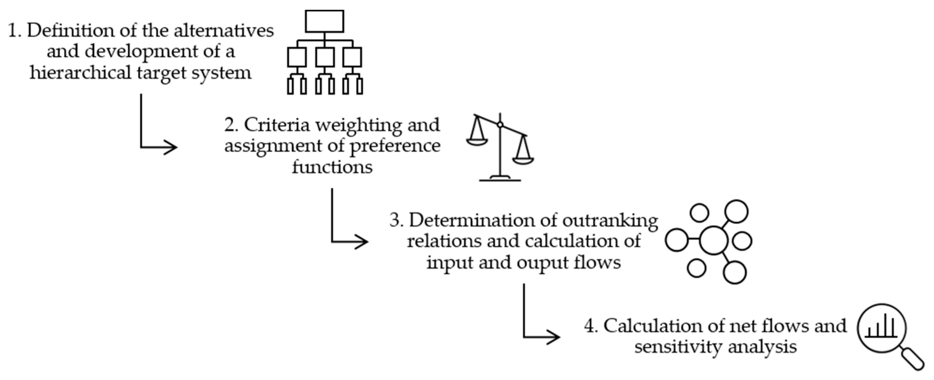
2.7. Methodology for the Systematic Selection of Marking Materials

The decision support process within the method for systematic selection of a marking agent for use in SLS is divided into four main phases (Figure 2). The methodology is based on the structure of a hierarchical target system according to the utility value analysis. The target system is then used for an evaluation of the alternatives according to the PROMETHEE method. The target system ensures a structured procedure for their derivation. The analysis by means of PROMETHEE II then enables a clear structure of the decision and a presentation of the results as a total order by generating a ranking list.

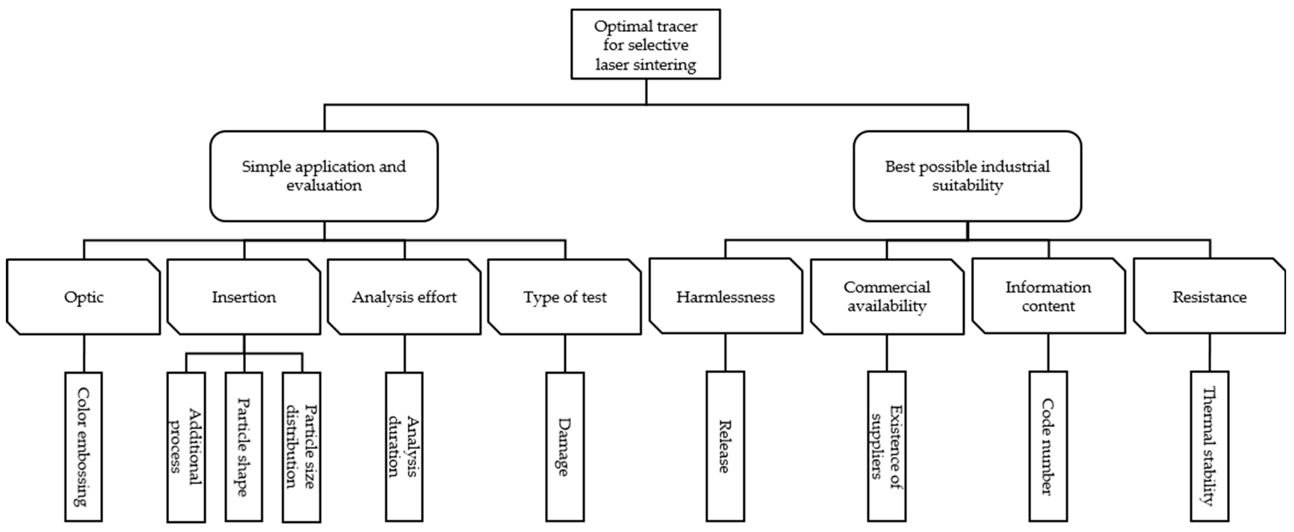
2.7.1. Definition of the Alternatives and Development of a Hierarchical Target System

According to the value system at hand, the different alternatives are defined by the deciding person or group of persons. This contains all options that represent a possible result of the decision. As shown in Table 1, three marking technologies are investigated for their suitability as marking agents for SLS:
  • Alternative a1: Modified polymers;
  • Alternative a2: Fluorescent particles;
  • Alternative a3: Silicate-encapsulated DNA.
Then, according to the first subtask of the utility value analysis [44], a hierarchical target system has to be developed, whereby the superordinate main target is divided into resulting sub-targets following the “top-down” design. The “top-down” methodology offers the advantage of being fully aware of the superordinate main goal [45]. Accordingly, the selection of the most suitable marking agent for SLS is identified as the overriding main objective. With regard to the requirements for a marking agent, it is basically assumed that influence on the requirements for a material for SLS mentioned in Schmid [2] also apply to a marking agent for SLS. In addition, Balzereit [70] sets out requirements for an additive for SLS, which are also taken into account in the definition of requirements. Based on the requirements from the literature, the process principle of SLS, and the available state of information on the individual material marking technologies, the following two main target groups are defined:
  • Objective main group 1: Simple application and evaluation;
  • Objective main group 2: Best possible industrial suitability.
The respective goals belonging to the target main groups are defined in the following. There may be overlap areas between individual decision dimensions, which can be merged to form combined requirements.
Target main group 1 includes the coloring of the marking agent and the introduction of the marking agent into the sinter material, the analysis effort, and the type of testing. It is considered whether an additional process step has to be implemented in the SLS process chain to ensure a homogeneous introduction of the marking agent into the sinter material [71,72,73]. During the introduction of the marking agent to the SLS, the influencing factor of powder rheology is particularly decisive as an evaluation criterion [2]. The powder rheological properties result from the particle shape and PSD [2,3]. As a general rule, the flow behavior of the powdered sinter material must not be influenced by the marking agent [2,5,18,74,75,76,77,78,79]. With regard to the particle shape, a shape that is as spherical as possible or analogous to the sinter material (Table 2 and Figure 1) is preferred [2,74,80,81]. Furthermore, the PSD of the marking agent should be in the range of the distribution of the sinter material (Table 2) [2,74,80,82]. In addition, for applicability as a marking technology, the marking agent should ostensibly not affect the aesthetics and perception of the sinter material and generated product [2,83,84]. In terms of aesthetics, the target group of optics is defined as a customer-relevant feature. Among other things, the component’s appearance is influenced by the color of the component, so marking agents that do not cause a color change in the sinter material (Figure 1) are preferred [2,83,84]. Moreover, a higher workload is disadvantageous compared to marking systems whose insertion can be carried out inhomogeneously, as they can already be integrated into the existing process steps of SLS. The analysis effort is described in terms of the time required to evaluate a material sample. Destructive testing is to be avoided with regard to the recycling of powder and the damage to components. Thus, a process without destruction of the powder or component is evaluated as positive.
The industrial suitability of the marking agent, as regraded by target main group 2, is defined by the harmlessness, commercial availability, possible code number, and resistance of the marking agent. Unless the marking agent is proven to be harmless via safety records, it is not suitable for a material marking technology [72]. Commercial availability describes the possibility of acquiring a marking agent in a suitable form from a supplier. The independent development and production of a marking agent is not preferred in the context of this work. The information content of a marking agent is described by the number of unique codes that can be generated. The number of codes is a measure for the application spectrum of the respective marking agent. The process temperature of SLS also requires the marking agent to be thermally stable. The marking agent must be detectable both in the recycled powder and in the component, and there must be no influence on the printing process due to the decomposition of the marking agent [2,3,6,35,71,72]. The melting temperature of the used sinter material (Table 2) is taken as the reference point for assessing the thermal resistance of the marking agent. Since SLS involves temperatures up to 210 °C [6], a safety margin of 10% is considered. A higher thermal resistance beyond the minimum requirement does not represent any added value for the application in SLS.
Based on the described targets, the hierarchical target system is set up (Figure 3).
Based on the hierarchical target system (Figure 3) and taking into account the used sinter material, the evaluation points of the individual criteria are obtained (Table 3).

2.7.2. Criteria Weighting and Assignment of Preference Functions

After defining the target system (Figure 3), specific weights are assigned to individual criteria (Table 3). The weighting of the criteria is based on a pairwise comparison by the authors. The following point scale is chosen to represent the preferences. Here, A is the criterion under consideration (row) and B is the comparison criterion (column). The even intermediate values allow a finer distinction and are used accordingly in the evaluation:
  • 1: strong preference of B over A;
  • 3: equivalence of A and B;
  • 5: strong preference of A over B.
The ratio of the sum of the single criterion to the total sum of the criteria is formed. Table 4 shows that the criterion of harmlessness (C7) was weighted as the most important criterion and the criterion of color expression (C1) as the least important criterion.
Thereupon, for each individual criterion, a preference function has to be defined additionally, on the basis of which the different alternatives are evaluated with respect to the criterion to be examined. The preference functions indicate the degree of preference of the user of an alternative an over an alternative am as a value within the interval from zero inclusive to one inclusive. Accordingly, the value zero expresses indifference and one expresses strong preference of an over am Equation (1) [43].
P ( a n ,   a m ) = { 0 ,   if   f ( a n ) f ( a m ) p [ f ( a n ) , f ( a m ) ] ,   if   f ( a n ) > f ( a m )
P ( a n , a m ) [ - ] Preference   function   from   a n   to   a m p [ f ( a n ) , f ( a m ) ] [ - ] Degree   of   preference   from   a n   to   a m f ( a n , a m ) Criterion ,   applied   to   a n   and   a m
The assignment of used preference functions is shown in Table 5 and is based on the judgment points defined in Table 3. Depending on the preference function, a decision can be made between indifference, strict preference, and an expression of weak preference [43,45]. Further information on the preference functions used in this work is listed in Brans and Vincke [43] and Geldermann and Lerche [45].

2.7.3. Determination of Outranking Relations and Calculation of Input and Output Flows

Once the criterion weights of the individual criteria (Table 4) and preference functions (Table 5) have been determined, the outranking relations of the alternatives are calculated on the basis of these. First, the preference values of the individual alternatives are determined on the basis of the selected preference functions. The product of the preference value of an alternative and the respective criteria weight results in a partial term for the calculation of the outranking relations. The sum of the partial terms results in the outranking relation of the examined alternative Equation (2) [43,45,47].
π ( a n , a m ) = k = 1 n w k · p k ( a n , a m )
π ( a n , a m ) [ - ] Outranking   relations   from   a n   to   a m w k [ - ] Criterion   weight p k ( a n , a m ) [ - ] Preference   value   of   the   alternative   a n   over   a m
Following the calculation of the outranking relations of all available alternatives, the input and output flows are calculated. The output flow of an alternative results from the normalized sum of the respective outranking relations Equation (3) [43,45,47]. Here, the summed results indicate in each case to what extent an alternative an is preferred over an alternative am. The input flow of an alternative is, therefore, calculated from the normalized sum of the respective outranking relations Equation (4) [43,45,47]. These provide information on the extent to which the alternative under consideration is inferior to the other alternatives [43,45,47].
ϕ n + = 1 i - 1 · k = 1 i π ( a n , a m )
ϕ n + [ - ] Output   flow   of   an   alternative   n π ( a n , a m ) [ - ] Outranking   relation   from   a n   to   a m
ϕ n - = 1 i - 1 · k = 1 i π ( a m , a n )
ϕ n - [ - ] Input   flow   of   an   alternative   n π ( a m , a n ) [ - ] Outranking   relation   from   a m   to   a n
The resulting matrix with outranking relations and input and output flows is shown in Table 6.

2.7.4. Calculation of Net Flow and Sensitivity Analysis

For evaluation, the previously calculated input and output flows (Table 6) are displayed graphically. The net flow is formed from the input and output flows for evaluation according to PROMETHEE II Equation (5) [43,45,47].
ϕ n net = ϕ n +   -   ϕ n -
ϕ n net [ - ] Net   flow   of   an   alternative   n ϕ n + [ - ] Output   flow   of   an   alternative   n ϕ n - [ - ] Input   flow   of   an   alternative   n
The results from the net flow calculation are to be ordered from largest to smallest net flow. The resulting complete preorder represents the alternative with largest net flow, as preferred, with respect to the evaluation [43,45,47]. Subsequently, the result is subjected to a sensitivity analysis to control the influence of individual weighting factors (Table 4) and the choice of preference functions (Table 5) [45]. An examination of the criteria weighting is performed by means of pairwise comparison with the deletion of the worst and best rated criterion. If a change in the ranking of the remaining criteria, a so-called “rank reversal”, occurs during a new evaluation, it indicates an instability within the evaluation system [45]. If the number of criteria available is insufficient for a rank reversal investigation or if a more far-reaching analysis is required, a variation in the criteria weights can provide an assessment of the sensitivity of the system.

3. Results

The various steps of the described methodology (Figure 2) are applied to the present use case and the results are presented.

3.1. Determination of the Outranking Relations and Calculation of the Input and Output Flows

The preference values are determined on the basis of the respective preference functions for all alternative combinations considered. Then, using Equation (2), the outranking relations of all alternative combinations are determined and transformed into Table 7. Based on Equations (3) and (4), the out- and input flows are then calculated.

3.2. Calculation of Net Flows for Evaluation According to PROMETHEE II

Based on the output and input flows of the alternatives listed in Table 7, the net flows are calculated using Equation (5) and shown in Figure 4.
The resulting total order of the studied alternatives is presented in the form of a ranking list in Table 8.
According to the evaluation, the modified polymers (a1) are the most favorable for the present application, followed by the fluorescent particles (a2).

3.3. Sensitivity Analysis

The robustness of the obtained result is checked by a sensitivity analysis using the “rank reversal” approach [45] when comparing the criteria weights pairwise. The criteria C7 as the most important and C1 as the least important are deleted (Table 4). As a result, a new Table 9 is obtained. The weighting and placement of the remaining criteria in relation to each other remains the same in relative terms.

4. Discussion

Fundamental to the subsequent experimental investigation of the suitability of the marking agents, this work first focused on the systematic selection of a suitable marking agent for use in SLS. Using the selection methodology, the alternative of modified polymers was evaluated as the most suitable alternative, followed by the alternative of fluorescent particles. The reason for this result is that the modified polymers do not affect the particle shape and PSD, as well as the flowability and processability of the sinter material. In addition, modified polymers have a higher information content than fluorescent particles. The fluorescent particles have a lower analysis time than modified polymers. This criterion does not have a significant effect on the result due to the existing application in SLS for analysis on demand and the criteria weighting. Furthermore, the fluorescent particles have a higher thermal stability than modified polymers. However, this condition is not relevant for the result due to the selected preference function. Although the silicate-encapsulated DNA has a higher information content and a more spherical particle shape than the other alternatives investigated, the criteria of commercial availability and thermal stability, as well as their weighting, have a significant effect on the suitability of the alternative for the present application. Furthermore, the fluorescent particles and the silicate-encapsulated DNA have a different color expression than the modified polymers. However, due to its low weighting, the color criterion is not decisive for the present decision.
Only generally available information on the marking agents and information from manufacturers was used in the selection process. In this work, properties of the marking agents were evaluated that may not correspond to the actual production process. Validation of this work in terms of traceability of the materials and feasibility for the SLS process is still to be conducted. A more in-depth investigation of material properties may be useful in the context of decision support and will provide a better basis for comparison. Provided an enlarged data base as well as other potential approaches to material marking are available, other marking technologies should also be considered in the decision-making process, possibly resulting in a different outcome within the scope of this work.
Due to the available information on the investigated marking agents (Table 1), only the targets listed in Figure 3 were investigated. The hierarchical target system (Figure 3) is exclusively suitable for the investigation carried out in this work. The selection of the individual target groups and targets as well as the design of the criteria is crucial for the complete decision support process. Therefore, for further investigations based on the selection methodology, the correctness of the underlying hierarchical target system must always be verified. In addition, the used target system can be supplemented by further dimensions and the evaluation result should be validated by experimental investigations. For example, the influence on the mechanical component properties [71] and the effect of the marking agent on the haptics of the resulting components [2,83,84,85] can be taken into account. This validation did not take place within the scope of this work, but will be part of a subsequent work. The chemical compatibility of the marking agent with the sinter material is decisive for the influence on the mechanical component properties [71,72]. The media compatibility of the marking agent must also be taken into account. Although only very low concentrations of a marking technology are present in the sinter material and no significant changes in the material and component properties are to be expected as a result, the influence of the marking technology must nevertheless be checked in subsequent investigations. In addition, the methodical influencing variables in SLS mentioned in Wegner [86], such as the process parameters in the manufacturing process, must be taken into account. According to this, the marking agent must not lead to an adjustment of the process parameters [2,84,85,87]. Moreover, the criterion of material marking costs of the investigated alternatives was not considered, since these are both partly still in the research stage and commercially not or only limited available. The material marking costs could vary depending on the available amount of material to be marked due to economies of scale. Furthermore, the present result of the evaluation is only valid for the underlying sinter material specified, which can differ, among other things, in particle shape, PSD, and color characteristics (Table 2 and Figure 1).
The use of the considered alternatives of modified polymers [37,55,59,60,62,88] and silicate-encapsulated DNA [53,58] is associated with high investment costs, especially due to the analytical technique (Table 1). This evaluation criterion was not considered in the present work. Paunescu et al. [65] emphasize economies of scale by minimizing the use of marking agents in the sinter material, although the profitability of this approach must first be proven in a real application. In the context of this work, only tracing processes for continuous storage of information from the starting material to the component were considered. The use of in-process databases offers a proven, low-cost alternative in conjunction with tracking methods such as data matrix or quick response coding on powder reservoirs and components [89] to the tracing approach. This presents a challenge for a marker-based tracing methodology.
The applied methodology allows a structured construction of the hierarchical target system as well as an in-depth discussion for preference determination. Furthermore, the expression of indifferences and incomparabilities is possible. In essence, it has to be considered in the applied methodology that in such a multi-criteria decision support process, subjective individual decisions always influence the result. Subjectivity manifests itself, for example, in the weighting of individual criteria by pairwise comparison or in the ranking of alternatives based on preference functions. Thus, a biased, manifested basic attitude has a lasting influence on the outcome of the decision support process. The user must always be aware of this limitation and take possible countermeasures. It is conceivable to carry out the decision process in a plenum. In addition, there are a variety of other methods for supporting a decision process [45,47] than can be used for the present use case.

5. Conclusions and Outlook

The idea of a marker-based traceability methodology for the purpose of process optimization was presented. The use of a marking material in SLS provides an agile system for the rapid and simple detection of spreading material properties such as the aging state and the composition of a polymer powder. Based on the provision of valid process, equipment, and component data, in-process quality assurance and timely correction of process parameters for the purpose of compensating for the material properties at hand are enabled. Fundamental to the subsequent experimental investigation of the suitability of the marking agents as well as the development of the tracing strategy in part II of the study, the aim of this work was initially the systematic selection of a suitable marker for use in SLS, taking into account the sinter material to be marked. Therefore, a set of marking technologies was evaluated using the selection methodology. The main conclusions can be summarized as follows:
  • The evaluated marking agents differ fundamentally in the functional principle, the number of possible codes, and the analysis method;
  • The applied methodology for the systematic selection of marking agents, based on a combination of utility analysis and the PROMETHEE method, is characterized by a structured design of the target system, an in-depth analysis for preference determination, and the expression of indifferences and incompatibilities;
  • The modified polymers are evaluated as the most suitable marking agent;
  • This result is due to the information content, particle shape, and PSD, as well as the thermal stability and commercial availability of the modified polymers.
Although the investigations carried out show that the applied methodology can be used to support the decision-making process for selecting the most suitable marking agent for SLS, this work creates scope for further investigations. Regarding the applied methodology, a deeper comparison of the different marking technologies sparks interest in order to verify and possibly extend the developed methodology to other approaches. For example, the PROMETHEE method offers further possibilities for displaying the results by means of layer visualizations and evaluations based on a preorder [45]. The marking technologies under study need be further investigated in the context of SLS. The experimental validation of these results with regard to the traceability of the materials and the feasibility for the SLS process will be presented in the part ΙΙ of this study. In particular, the influence of the marking agent on the material and component properties as well as the effect of the SLS process on the stability of the marking agent are to be investigated in the future. Based on the used marking agent and the experimental findings, a suitable coding strategy is to be developed. For this purpose, specific concentrations and/or types of marking agents could be added to the sinter material, which can be uniquely identified at different, predefined stations in the SLS process chain. A promising approach for further investigations is the use of components as combined material data storage [59,90,91]. The storage of manufacturer-, process-, or product-related data in a product could be an alternative or complement to blockchain technologies [92].

Author Contributions

T.E.: Conceptualization, methodology, validation, formal analysis, investigation, resources, data curation, writing—original draft preparation, writing—review and editing, visualization, and funding acquisition; F.v.L.: Conceptualization, resources, supervision, validation, and writing—review and editing; F.v.d.K.: Conceptualization, methodology, validation, formal analysis, investigation, and data curation; A.-K.R.: Conceptualization, resources, and validation; A.H.: Conceptualization, resources, supervision, validation, and writing—review and editing; K.D.: project administration, resources, and writing—review and editing; All authors have read and agreed to the published version of the manuscript.

Funding

We acknowledge support by the Open Access Publication Funds of Technische Universität Braunschweig.

Institutional Review Board Statement

Not applicable.

Informed Consent Statement

Not applicable.

Data Availability Statement

The raw/processed data required to reproduce these findings cannot be shared at this time as the data also form part of an ongoing study.

Acknowledgments

The authors would like to thank the companies Polysecure GmbH (Freiburg, Germany) and Tailorlux GmbH (Münster, Germany) for providing information and the technical support.

Conflicts of Interest

The authors declare no conflict of interest. The results, opinions, and conclusions expressed in this publication are not necessarily those of Volkswagen Aktiengesellschaft.

References

  1. Seppala, J.E.; Kotula, A.P.; Snyder, C.R. Polymer-Bzased Additive Manufacturing: Recent Developments; American Chemical Society: Washington, DC, USA, 2020; ISBN 9780841234260. [Google Scholar]
  2. Schmid, M. Selektives Lasersintern (SLS) Mit Kunststoffen: Technologie, Prozesse und Werkstoffe; Hanser: München, Germany, 2015; ISBN 978-3-446-44562-8. [Google Scholar]
  3. Gibson, I.; Rosen, D.; Stucker, B. Additive Manufacturing Technologies: 3D Printing, Rapid Prototyping and Direct Digital Manufacturing, 2nd ed.; Springer: New York, NY, USA; Heidelberg, Germany; Dodrecht, The Netherlands; London, UK, 2015; ISBN 978-1-4939-2112-6. [Google Scholar]
  4. Celik, E. Additive Manufacturing: Science and Technology, 1st ed.; De Gruyter: Berlin, Germany; Boston, MA, USA, 2020; ISBN 9781501518782. [Google Scholar]
  5. Breuninger, J.; Becker, R.; Wolf, A.; Rommel, S.; Verl, A. Generative Fertigung mit Kunststoffen: Konzeption und Konstruktion für Selektives Lasersintern; Springer: Berlin, Germany; Heidelberg, Germany, 2013; ISBN 978-3-642-24324-0. [Google Scholar]
  6. Gebhardt, A. Additive Fertigungsverfahren: Additive Manufacturing und 3D-Drucken für Prototyping—Tooling—Produktion, 5., neu Bearbeitete und Erweiterte Auflage; Hanser: München, Germany, 2016; ISBN 978-3-446-44401-0. [Google Scholar]
  7. Fastermann, P. 3D-Druck/Rapid Prototyping: Eine Zukunftstechnologie—Kompakt Erklärt; Springer: Berlin, Germany; Heidelberg, Germany, 2012; ISBN 978-3-642-29224-8. [Google Scholar]
  8. Berger, U.; Hartmann, A.; Schmid, D. 3D-Druck—Additive Fertigungsverfahren: Rapid Prototyping, Rapid Tooling, Rapid Manufacturing, 2. Auflage; Verlag Europa-Lehrmittel—Nourney Vollmer GmbH & Co. KG: Haan-Gruiten, Germany, 2017; ISBN 978-3-8085-5034-2. [Google Scholar]
  9. Choren, J.; Gervasi, V.; Herman, T.; Kamara, S.; Mitchell, J. SLS powder life study. In Proceedings of the 2001 Solid Freeform Fabrication Symposium, Austin, TX, USA, 6–8 August 2001; pp. 39–45. [Google Scholar]
  10. Dahlmann, R.; Haberstroh, E.; Menges, G. Menges Werkstoffkunde Kunststoffe, Vollständig neu Bearbeitete Auflage, 7th ed.; Hanser: Munich, Germany, 2022; ISBN 978-3-446-45801-7. [Google Scholar]
  11. DIN 50035:2012-09. Begriffe auf dem Gebiet der Alterung von Materialien—Polymere Werkstoffe. Beuth Verlag GmbH: Berlin, Germany, 2012.
  12. Wudy, K.; Drummer, D. Aging effects of polyamide 12 in selective laser sintering: Molecular weight distribution and thermal properties. Addit. Manuf. 2019, 25, 1–9. [Google Scholar] [CrossRef]
  13. Zarringhalam, H.; Hopkinson, N.; Kamperman, N.F.; de Vlieger, J.J. Effects of processing on microstructure and properties of SLS Nylon 12. Mater. Sci. Eng. A 2006, 435-436, 172–180. [Google Scholar] [CrossRef] [Green Version]
  14. Dadbakhsh, S.; Verbelen, L.; Verkinderen, O.; Strobbe, D.; van Puyvelde, P.; Kruth, J.-P. Effect of PA12 powder reuse on coalescence behaviour and microstructure of SLS parts. Eur. Polym. J. 2017, 92, 250–262. [Google Scholar] [CrossRef]
  15. Pham, D.; Dotchev, K.; Yusoff, W. Deterioration of polyamide powder properties in the laser sintering process. Proc. Inst. Mech. Eng. Part C-J. Mech. Eng. Sci. 2008, 222, 2163–2176. [Google Scholar] [CrossRef]
  16. Wudy, K.; Drummer, D.; Kühnlein, F.; Drexler, M. Influence of degradation behavior of polyamide 12 powders in laser sintering process on produced parts. In Proceedings of the PPS-29: The 29th International Conference of the Polymer Processing Society—Conference Papers, Nuremberg, Germany, 15–19 July 2013; American Institute of Physics: College Park, MD, USA, 2014; pp. 691–695. [Google Scholar]
  17. Plastics Failure: Analysis and Prevention; Moalli, J. (Ed.) Plastics Design Library: Norwich, NY, USA, 2010; ISBN 1-884207-92-8. [Google Scholar]
  18. Hesse, N.; Dechet, M.A.; Bonilla, J.S.G.; Lübbert, C.; Roth, S.; Bück, A.; Schmidt, J.; Peukert, W. Analysis of tribo-charging during powder spreading in Selective Laser Sintering: Assessment of polyamide 12 powder ageing effects on charging behavior. Polymers 2019, 11, 609. [Google Scholar] [CrossRef] [Green Version]
  19. Fiedler, L.; Androsch, R.; Mileva, D.; Radusch, H.J.; Wutzler, A.; Gerken, J. Experimentelle Simulation der physikalischen Alterung von Lasersinterpulvern. Z. Kunstst. 2010, 6, 19–32. [Google Scholar]
  20. Josupeit, S.; Lohn, J.; Hermann, E.; Gessler, M.; Tenbrink, S.; Schmid, H.-J. Material Properties of Laser Sintered Polyamide 12 as Function of Build Cycles Using Low Refresh Rates. In Proceedings of the 26th Annual International Solid Freeform Fabrication Symposium, Austin, TX, USA, 10–12 August 2015; pp. 540–549. [Google Scholar]
  21. Dotchev, K.; Yusoff, W. Recycling of polyamide 12 based powders in the laser sintering process. Rapid Prototyp. J. 2009, 15, 192–203. [Google Scholar] [CrossRef]
  22. Mielicki, C. Prozessnahes Qualitätsmanagement beim Lasersintern von Polyamid 12. Ph.D. Thesis, Universität Duisburg-Essen, Essen, Germany, 2014. [Google Scholar]
  23. Wegner, A.; Mielicki, C.; Grimm, T.; Gronhoff, B.; Witt, G.; Wortberg, J. Determination of Robust Material Qualities and Processing Conditions for Laser Sintering of Polyamide 12. Polym. Eng. Sci. 2014, 54, 1540–1554. [Google Scholar] [CrossRef]
  24. Wegner, A.; Witt, G. Betrachtung zur Pulvernutzungsdauer beim Laser-Sintern und Einfluss der Prozessführung auf die Entstehung von Ausschussbauteilen. Aachen University of Applied Sciences: Aachen, Germany. RTejournal- Forum Für Rapid Technol. 2012, 9. [Google Scholar]
  25. Pham, D.; Dotchev, K.; Yusoff, W. Improvement of part surface finishing in laser sintering by experimental design optimisation (DOE). In Proceedings of the Third Virtual International Conference on Innovative Production Machines and Systems (IPROMS 2007), Cardiff, UK, 2–13 July 2007. [Google Scholar]
  26. Yusoff, W.A.; Thomas, A.J. The effect of employing an effective laser sintering scanning strategy and energy density value on eliminating “orange peel” on a selective laser sintered part. IAMOT Proc. Dicec 2008, 6. [Google Scholar]
  27. Esper, F.J. Pulvermetallurgie: Das Flexible und Fortschrittliche Verfahren für Wirtschaftliche und Zuverlässige Bauteile; Expert-Verl.: Renningen, Malmsheim, 1996; ISBN 9783816913214. [Google Scholar]
  28. GSI AISBL. GS1 Global Traceability Standard—GS1’s Framework for the Design of Interoperable Traceability Systems for Supply chains. 2017. Available online: https://www.gs1.org/sites/default/files/docs/traceability/GS1_Global_Traceability_Standard_i2.pdf (accessed on 17 June 2022).
  29. Handbuch Fügen, Handhaben, Montieren; Feldmann, K.; Schöppner, V.; Spur, G. (Eds.) vollständig neu bearbeitete Auflage; Hanser: München, Germany, 2014; ISBN 978-3-446-42827-0. [Google Scholar]
  30. Taschenlexikon Logistik: Abkürzungen, Definitionen und Erläuterungen der Wichtigsten Begriffe aus Materialfluss und Logistik; ten Hompel, M.; Heidenblut, V. (Eds.) bearb. und erw. Aufl.; Springer: Berlin, Germany; Heidelberg, Germany, 2011; ISBN 978-3-642-19944-8. [Google Scholar]
  31. Wegner-Hambloch, S. Rückverfolgbarkeit in der Praxis: Artikel 18 und 19 der VO (EG) Nr. 178/2002 Schnell und Einfach Umgesetzt, 1st ed.; Behr: Hamburg, Germany, 2005; ISBN 978-3-89947-137-3. [Google Scholar]
  32. Wortberg, J. Qualitätssicherung in der Kunststoffverarbeitung: Rohstoff-, Prozess- und Produktqualität; Tabellen; Hanser: München, Germany; Wien, Austria, 1996; ISBN 9783446171336. [Google Scholar]
  33. Huber, W. Industrie 4.0 Kompakt—wie Technologien Unsere Wirtschaft und Unsere Unternehmen Verändern: Transformation und Veränderung des gesamten Unternehmens; Springer Vieweg: Wiesbaden, Germany, 2018; ISBN 978-3-658-20798-4. [Google Scholar]
  34. Vöpel, H. Disruption: Neuvermessung Einer Ver-Rückten Welt; Books on Demand GmbH: Norderstedt, Germany, 2020; ISBN 9783750436145. [Google Scholar]
  35. Eyerer, P.; Elsner, P.; Hirth, T. Polymer Engineering: Technologien und Praxis; Springer: Berlin, Germany; Heidelberg, Germany, 2008; ISBN 978-3-540-72402-5. [Google Scholar]
  36. Porter, M.E.; Heppelmann, J.E. Wie smarte Produkte unternehmen verändern. Harv. Bus. Manag. 2015, 37, 53–73. [Google Scholar]
  37. Lutz, J.-F. Les Polymères, Messagers à l’Échelle Moléculaire. IT Ind. Technol. 2021, 1–11. [Google Scholar]
  38. Fornos, P.; Aramendia, S.P.; Muela, D.R.; Ribes, S.S. An Apparatus and a Method for Determining a Quantity of Material. U.S. Patent Application No.15/542,394, 25 January 2018. [Google Scholar]
  39. Blattmeier, M. Strukturanalyse von lasergesinterten Schichtverbunden mit werkstoffmechanischen Methoden; Springer Vieweg: Wiesbaden, Germany, 2012; ISBN 978-3-8348-2500-1. [Google Scholar]
  40. Hachmöller, R. Methoden zur Zielkostenerreichung bei Innovativen Kaufteilen: Eine Theoretische und Empirische Untersuchung, 1. Aufl.; TCW Transfer-Centrum: München, Germany, 2006; ISBN 3-937236-33-3. [Google Scholar]
  41. Kröll, M. Methode zur Technologiebewertung für eine Ergebnisorientierte Produktentwicklung. Zugl.: Stuttgart, Univ., Diss., 2007; Jost-Jetter-Verl.: Heimsheim, Germany, 2007; ISBN 978-3-939890-26-3. [Google Scholar]
  42. Lebens, U.J. Diskontinuitäten bei Fertigungstechniken: Eine Empirirische Studie zur Bewältigung von Technologischen Diskontinuitäten; gmft Ges. für Management und Technologie: München, Germany, 1986; ISBN 3-924483-34-5. [Google Scholar]
  43. Brans, J.-P.; Vincke, P. Note—A Preference Ranking Organisation Method: (The PROMETHEE Method for Multiple Criteria Decision-Making). Manag. Sci. 1985, 31, 647–656. [Google Scholar] [CrossRef] [Green Version]
  44. Dittmer, G. Managen mit Methode: Instrumente für individuelle Lösungen; Gabler Verlag: Wiesbaden, Germany, 1995; ISBN 978-3-409-18790-9. [Google Scholar]
  45. Geldermann, J.; Lerche, N. Leitfaden zur Anwendung von Methoden der multikriteriellen Entscheidungsunterstützung: Methode: Promethee; Lehrstuhl für Produktion und Logistik, Georg-August-Universität Göttingen: Göttingen, Germany, 2014. [Google Scholar]
  46. Hwang, C.-L.; Yoon, K. Multiple Attribute Decision Making: Methods and Applications A State-of-the-Art Survey; Springer: Berlin, Germany; Heidelberg, Germany, 1981; ISBN 978-3-540-10558-9. [Google Scholar]
  47. Zimmermann, H.-J.; Gutsche, L. Multi-Criteria Analyse: Einführung in die Theorie der Entscheidungen bei Mehrfachzielsetzungen; Springer: Berlin, Germany; Heidelberg, Germany, 1991; ISBN 978-3-540-54483-8. [Google Scholar]
  48. Lehmann&Voss&Co. KG. LUVOSINT PA12 9270 BK—Polyamide 12 Unreinforced, Black: Preliminary Datasheet; Lehmann&Voss&Co. KG: Hamburg, Germany, 2022. [Google Scholar]
  49. Goodridge, R.D.; Tuck, C.J.; Hague, R. Laser sintering of polyamides and other polymers. Prog. Mater. Sci. 2012, 57, 229–267. [Google Scholar] [CrossRef]
  50. Amado, A.; Schmid, M.; Levy, G.; Wegener, K. Advances in SLS powder characterization. In Proceedings of the 22nd Annual International Solid Freeform Fabrication Symposium—An Additive Manufacturing Conference, SFF 2011, Austin, TX, USA, 8–10 August 2011. [Google Scholar]
  51. Dost, G.; Kummer, B.; Matloubi, M.; Moesslein, J.; Treick, A. Produkt- und Materialpässe Nützen der Kreislaufwirtschaft nur, Wenn sie tatsächlich Robust mit Produkten und Materialien Verknüpft sind!: Kurzfassung; Polysecure GmbH: Freiburg, Germany, 2022; Available online: https://polysecure.eu/fileadmin/main/Unternehmen/Media-Files/220425_Produkt_Materialpass_Kurzfassung_Dt.pdf (accessed on 20 August 2022).
  52. Dost, G.; Matloubi, M.; Treick, A.; Kummer, B. Booster für eine gelingende Kreislaufwirtschaft. Recycl. Mag. Sonderh. 2022, 4, 84–86. [Google Scholar]
  53. Paunescu, D.; Puddu, M.; Soellner, J.O.B.; Stoessel, P.R.; Grass, R.N. Reversible DNA encapsulation in silica to produce ROS-resistant and heat-resistant synthetic DNA’fossils’. Nat. Protoc. 2013, 8, 2440–2448. [Google Scholar] [CrossRef] [PubMed]
  54. Buttitta, A. „Tracer-Based-Sorting"—Die Zukunft der Kunststoffverwertung. EU-Recycl. —Das Fachmag. Eur. Recycl. 2021, 38, 16–18. [Google Scholar]
  55. Al Ouahabi, A.; Amalian, J.-A.; Charles, L.; Lutz, J.-F. Mass spectrometry sequencing of long digital polymers facilitated by programmed inter-byte fragmentation. Nat. Commun. 2017, 8, 1–8. [Google Scholar] [CrossRef] [Green Version]
  56. Brunner, S.; Fomin, P.; Kargel, C. Automated sorting of polymer flakes: Fluorescence labeling and development of a measurement system prototype. Waste Manag. 2015, 38, 49–60. [Google Scholar] [CrossRef]
  57. Woidasky, J.; Sander, I.; Schau, A.; Moesslein, J.; Wendler, P.; Wacker, D.; Gao, G.; Kirchenbauer, D.; Kumar, V.; Busko, D.; et al. Inorganic fluorescent marker materials for identification of post-consumer plastic packaging. Resour. Conserv. Recycl. 2020, 161, 104976. [Google Scholar] [CrossRef]
  58. Grass, R.N.; Stark, W.J. Molecular Code System. U.S. Patent Application No.14/384,852, 26 December 2017. [Google Scholar]
  59. Lutz, J.-F. Coding macromolecules: Inputting information in polymers using monomer-based alphabets. Macromolecules 2015, 48, 4759–4767. [Google Scholar] [CrossRef]
  60. Amalian, J.-A.; Mondal, T.; Konishcheva, E.; Cavallo, G.; Petit, B.E.; Lutz, J.-F.; Charles, L. Desorption electrospray ionization (DESI) of digital polymers: Direct tandem mass spectrometry decoding and imaging from materials surfaces. Adv. Mater. Technol. 2021, 6, 2001088. [Google Scholar] [CrossRef]
  61. Paunescu, D.; Mora, C.A.; Querci, L.; Heckel, R.; Puddu, M.; Hattendorf, B.; Günther, D.; Grass, R.N. Detecting and number counting of single engineered nanoparticles by digital particle polymerase chain reaction. ACS Nano 2015, 9, 9564–9572. [Google Scholar] [CrossRef] [PubMed]
  62. Youssef, I.; Carvin-Sergent, I.; Konishcheva, E.; Kebe, S.; Greff, V.; Karamessini, D.; Matloubi, M.; Ouahabi, A.A.; Moesslein, J.; Amalian, J.-A.; et al. Covalent Attachment and Detachment by Reactive DESI of Sequence-Coded Polymer Taggants. Macromol. Rapid Commun. 2022, 2200412. [Google Scholar] [CrossRef]
  63. Karamessini, D.; Simon-Yarza, T.; Poyer, S.; Konishcheva, E.; Charles, L.; Letourneur, D.; Lutz, J.-F. Abiotic Sequence-Coded Oligomers as Efficient In Vivo Taggants for the Identification of Implanted Materials. Angew. Chem. Int. Ed. 2018, 57, 10574–10578. [Google Scholar] [CrossRef]
  64. Tailorlux GmbH. Sicherheitsdatenblatt gemäß Verordnung (EG) 1907/2006: Anorganische Fluoreszenz Rot; Tailorlux GmbH: Münster, Germany, 2022. [Google Scholar]
  65. Paunescu, D.; Stark, W.J.; Grass, R.N. Particles with an identity: Tracking and tracing in commodity products. Powder Technol. 2016, 291, 344–350. [Google Scholar] [CrossRef]
  66. ISO 13322-2:2021-12. Particle Size Analysis—Image Analysis Methods—Part 2: Dynamic Image Analysis Methods. Internation Organization of Standardization: Geneva, Switzerland, 2021.
  67. Wadell, H. Volume, Shape, and Roundness of Quartz Particles. J. Geol. 1935, 43, 250–280. [Google Scholar] [CrossRef]
  68. Frick, A.; Stern, C. Einführung in die Kunststoffprüfung: Prüfmethoden und Anwendungen; Hanser: München, Germany, 2017; ISBN 978-3-446-44351-8. [Google Scholar]
  69. DIN EN ISO 11357-1:2017-02. Kunststoffe_- Dynamische Differenz-Thermoanalyse_(DSC)_- Teil_1: Allgemeine Grundlagen (ISO_11357-1:2016). Deutsche Fassung EN_ISO_11357-1:2016. Beuth Verlag GmbH: Berlin, Germany, 2017.
  70. Balzereit, S. Strukturen und Eigenschaften selektiv lasergesinterter Polyamid- und Polyamid-Kupfer-Systeme für Anwendungen in dreidimensionalen Schaltungsträgern. Ph.D. Thesis, Universität Bayreuth, Bayreuth, Germany, 2020. [Google Scholar]
  71. Franke, J. Räumliche elektronische Baugruppen (3D-MID)-Werkstoffe. In Herstellung, Montage und Anwendungen für Spritzgegossene Schaltungsträger; Carl Hanser Verlag: Munich, Germany, 2013. [Google Scholar]
  72. Wißbrock, H. Ein neues Verfahren im Spiel eingeführter MID-Technologien: Laser-Direkt-Strukturieren von Kunststoffen. Kunststoffe 2002, 11, 2–7. [Google Scholar]
  73. Naundorf, G.; Wissbrock, H. A fundamentally new mechanism for additive metallization of polymeric substrates in ultra fine line technology illustrated for 3D-MIDs. Galvanotechnik 2000, 91, 2449–2451. [Google Scholar]
  74. Keller, B. Rapid Prototyping: Grundlagen zum selektiven Lasersintern von Polymerpulver. Ph.D. Thesis, Universität Stuttgart, Stuttgart, Germany, 1998. [Google Scholar]
  75. Steinberger, J. Optimierung des Selektiven-Laser-Sinterns zur Herstellung von Feingußteilen für die Luftfahrtindustrie. Ph.D. Thesis, Technische Universität München, Düsseldorf, Germany, 2001. [Google Scholar]
  76. Tontowi, A.E. Selective Laser Sintering of Crystalline Polymers. Ph.D. Thesis, University of Leeds (School of Mechanical Engineering), Leeds, UK, 2000. [Google Scholar]
  77. Drexler, M.; Drummer, D.; Kühnlein, F.; Wudy, K. Selektives Strahlschmelzen von Kunststoffen-Grundlagenwissenschaftliche Prozessanalyse und Simulation. Ind. Sonderforschungsbereichs 814 2012, 27–48. [Google Scholar]
  78. Masuda, H.; Higashitani, K.; Yoshida, H. Powder Technology: Fundamentals of Particles, Powder Beds, and Particle; CRC Press: Boca Raton, FL, USA, 2019; ISBN 9780367389802. [Google Scholar]
  79. Schulze, D. Pulver und Schüttgüter; Springer: Berlin/Heidelberg, Germany, 2019; ISBN 978-3-662-58775-1. [Google Scholar]
  80. Alscher, G. Das Verhalten Teilkristalliner Thermoplaste Beim Lasersintern. Ph.D Thesis, Berichte aus der Kunststofftechnik, Universität Essen, Aachen, Germany, 2000. [Google Scholar]
  81. Rietzel, D.; Kühnlein, F.; Drummer, D. Selektives Lasersintern von teilkristallinen Thermoplasten. University of Erlangen-Nuremberg, Erlangen, Nuremberg, Germany. RTejournal-Forum Für Rapid Technol. 2011. [Google Scholar]
  82. Nöken, S. Technologie des Selektiven Lasersinterns von Thermoplasten. Ph.D Thesis, RWTH Aachen, Aachen, Germany, 1997. [Google Scholar]
  83. Ashby, M.F.; Johnson, K. Materials and Design: The Art and Science of Material Selection in Product Design, 3rd ed.; Elsevier/Butterworth-Heinemann: Amsterdam, The Netherlands, 2014; ISBN 978-0-08-098205-2. [Google Scholar]
  84. Kaddar, W. Die generative Fertigung mittels Laser-Sintern: Scanstrategien, Einflusse verschiedener Prozessparameter auf die mechanischen und optischen Eigenschaften beim LS von Thermoplasten und deren Nachbearbeitungsmoglichkeiten. Ph.D. Thesis, Universität Duisburg-Essen, Essen, Germany, 2010. [Google Scholar]
  85. Knittka, W.; Eichmann, M.; Witt, G.; Gath, C.; Wudy, K.; Drummer, D. Thermisches und optisches Verhalten LDS-funktionalisierter Pulver für das selektive Lasersintern/Thermal and Optical Behavior of LDS-functionalized Powders for Selective Laser Sintering. Rapid. Tech 2016, 210–224. [Google Scholar] [CrossRef]
  86. Wegner, A. Theorie über die Fortführung von Aufschmelzvorgängen als Grundvoraussetzung für eine robuste Prozessführung beim Laser-Sintern von Thermoplasten. Ph.D. Thesis, Universität Duisburg-Essen, Essen, Germany, 2015. [Google Scholar]
  87. Laumer, T.; Stichel, T.; Appel, P.; Amend, P. Untersuchungen zum Absorptionsverhalten von Pulverschüttungen für das Laserstrahlschmelzen von Kunststoffen. Erfurt, Germany. Rapid. Tech Proc. Erf. Ger. 2013, 2013. [Google Scholar]
  88. Gunay, U.S.; Petit, B.E.; Karamessini, D.; Al Ouahabi, A.; Amalian, J.-A.; Chendo, C.; Bouquey, M.; Gigmes, D.; Charles, L.; Lutz, J.-F. Chemoselective synthesis of uniform sequence-coded polyurethanes and their use as molecular tags. Chem 2016, 1, 114–126. [Google Scholar] [CrossRef] [Green Version]
  89. Prockl, G.; Bauer, A.; Pflaum, A.; Müller-Steinfahrt, U. Entwicklungspfade und Meilensteine Moderner Logistik: Skizzen Einer Roadmap; Gabler Verlag: Wiesbaden, Germany, 2004; ISBN 978-3-322-89045-0. [Google Scholar]
  90. Pilz, H.; Rehme, O.; Schäfer, M. Verfahren Zum Herstellen Eines Markierten Gegenstandes. DE 10 2009 043 597 A1 7 April 2011. [Google Scholar]
  91. Lee, H.H.; Kalhor, R.; Goela, N.; Bolot, J.; Church, G.M. Terminator-free template-independent enzymatic DNA synthesis for digital information storage. Nat. Commun. 2019, 10, 1–12. [Google Scholar] [CrossRef]
  92. Tatje, C. Der Lack ist ab: Sitze zerfallen auf Knopfdruck, Klebstoffe gibt es nicht mehr—Und Mais und Reis ersetzen Leder. Bei BMW arbeiten sie am ersten wiederverwertbaren Auto. Wird es irgendwann auch fahren? DIE ZEIT 2022, 12, 24. [Google Scholar]
Figure 1. SEM image of the used sinter material. Produced with Tescan Mira 3 at 150× magnification.
Materials 16 01043 g001
Figure 2. Establishment of the methodology for the systematic selection of a marking agent for a material marking in SLS.
Materials 16 01043 g002
Figure 3. Established hierarchical target system for the present use case.
Materials 16 01043 g003
Figure 4. Presentation of results for the examined alternatives.
Materials 16 01043 g004
Table 1. Available properties of the investigated marking agents.
CriterionModified PolymersReferencesFluorescent ParticlesReferencesSilicate-Encapsulated DNAReferences
Thermal resistance380 °C[51,52]800 °C–1700 °C*140 °C[53]
Additional processYes[51,52], Application by spray drying and mixing processYesMixing processYesMixing process
Particle shapeAnalogous to sinter materialApplication by spray dryingJagged*Spherical[53]
Particle size distributionAnalogous to sinter materialApplication by spray dryingCustomizable*60 nm–250 nm[53]
Concentration in sinter material1 ppm[37,51,52,54,55]>800 ppm*, [56,57]<1 ppm[58]
Color deviation from sinter materialNoAnalogous to sinter material, due to application by spray dryingYes*Yes[53]
Analysis duration~1 min[59,60]10 ms–1000 ms; ~100 ms*90 min[61]
Type of testNon-destructive
(DESI-MS/MS **)
[60,62]Non-destructive
(Fluorescence spectrometry)
[56]Destructive
(PCR ****-duplication and gel electrophoresis)
[53,58]
Harmlessness ***Yes[63]Yes[64]Yes[65]
Commercial availabilityYes[37,51,52,62]Yes[64]No/
Number of possible codings264
(64 Bits)
[55]210
(10 Bits)
[56]460
(120 Bits)
[65]
* Manufacturer information. ** Desorption electrospray ionization tandem mass spectrometry. *** Harmlessness in the present concentration in the sinter material. **** Polymerase chain reaction.
Table 2. Investigated properties of the used sinter material.
PropertyExpression
Melting temperature181.9 °C
Sphericity0.838
Aspect ratio0.710
Particle size distribution28.2 µm-d10
66.3 µm-d50
100.0 µm-d90
Table 3. Assessment points of the individual criteria.
NumberCriterionAssessment Point
C1Color embossingDifferent color
C2Additional processYes/No
C3Particle shapeSpherical, “potato shaped”, jagged
C4Particle size distributionBetween 28.2 µm-d10 and 100.0 µm-d90
C5Analysis durationTime [min]
C6Non-destructive testingYes/No
C7HarmlessnessYes/No
C8Commercial availabilityYes/No
C9Information contentNumber of codings
C10Thermal resistanceAt least 200 °C
Table 4. Pairwise comparison for the weighting of the criteria examined. The pairwise comparison is carried out by the authors. The weighting results from the ratio of the sum of the single criterion to the total sum of the criteria.
CriteriaC1C2C3C4C5C6C7C8C9C10ƩWeight
C1-222231121160.059
C24-22441241240.089
C343-3441241260.097
C4443-441241270.100
C54222-41241220.082
C632222-1131170.063
C7555555-454430.160
C85444452-42340.126
C942222312-1190.071
C10555555245-410.152
2691.0
Table 5. Assignment of the used preference functions.
NumberCriteriaPreference Functionqp
C1Color embossingOrdinary criterion--
C2Additional processOrdinary criterion--
C3Particle shapeCriterion with linear preference and indifference rangeSimilar particlesSpherical versus fissured particles
C4Particle size distributionCriterion with linear preference and indifference range[28.2 µm; 100.0 µm]±30 µm outside the interval
C5Analysis durationCriterion with linear preference->30 min difference
C6Non-destructive testingOrdinary criterion--
C7HarmlessnessOrdinary criterion--
C8Commercial availabilityOrdinary criterion--
C9Information contentCriterion with linear preference->100 Codes difference
C10Thermal resistanceOrdinary criterion--
Table 6. PROMETHEE matrix with outranking relations and input and output flows [43,45,47].
a1a2a3ϕ+
a1-π1,2π1,3ϕ1+
a2π2,1-π2,3ϕ2+
a3π3,1π3,2-ϕ3+
ϕϕ1ϕ2ϕ3
Table 7. Matrix of the determined outranking relations as well as input and output flows.
a1a2a3
a1-0.2090.5840.793
a20.082-0.5240.606
a30.1670.167-0.335
0.2490.3761.108
Table 8. Ranking of the studied alternatives.
PlacementAlternativeNet Flow
1Modified polymers (a1)0.544
2Fluorescent particles (a2)0.230
3Silicate-encapsulated DNA (a3)−0.773
Table 9. Pairwise comparison as sensitivity analysis according to the “rank reversal” approach. The weighting and placement of the remaining criteria in relation to each other remains the same in relative terms.
CriteriaC2C3C4C5C6C8C9C10ƩWeightOld PlacementNew Placement
C2-2244241190.11465
C33-344241210.12654
C443-44244220.13243
C5222-4241170.10276
C62222-131130.07898
C844445-42270.16232
C9222232-1140.08487
C105555545-340.20421
1671.0
Disclaimer/Publisher’s Note: The statements, opinions and data contained in all publications are solely those of the individual author(s) and contributor(s) and not of MDPI and/or the editor(s). MDPI and/or the editor(s) disclaim responsibility for any injury to people or property resulting from any ideas, methods, instructions or products referred to in the content.

