
Development of the Dual-Beam Ion Irradiation Facility for Fusion Materials (DiFU)

 , , and
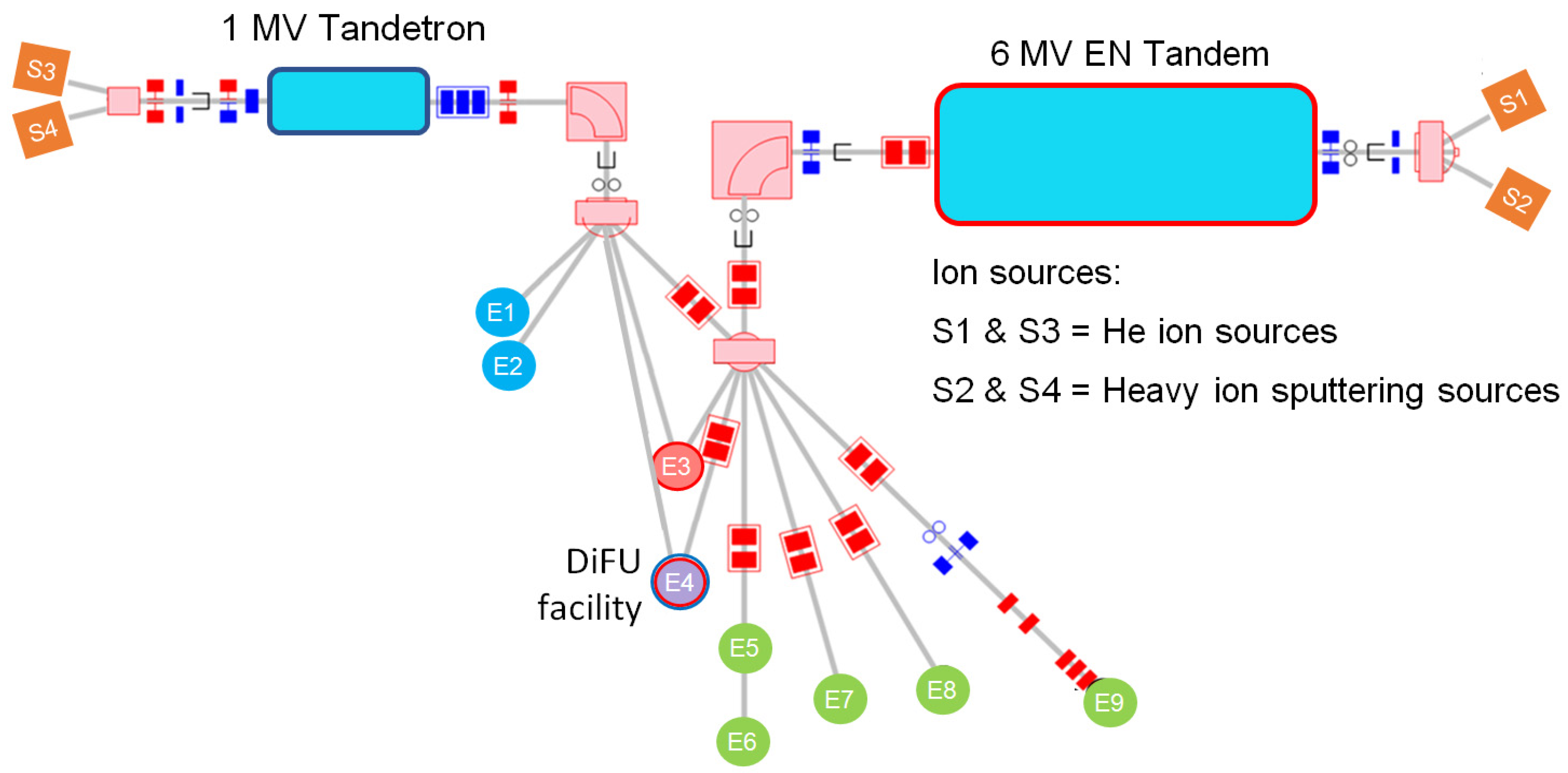
Abstract
1. Introduction
2. Materials and Methods
2.1. Accelerators and Ion Sources
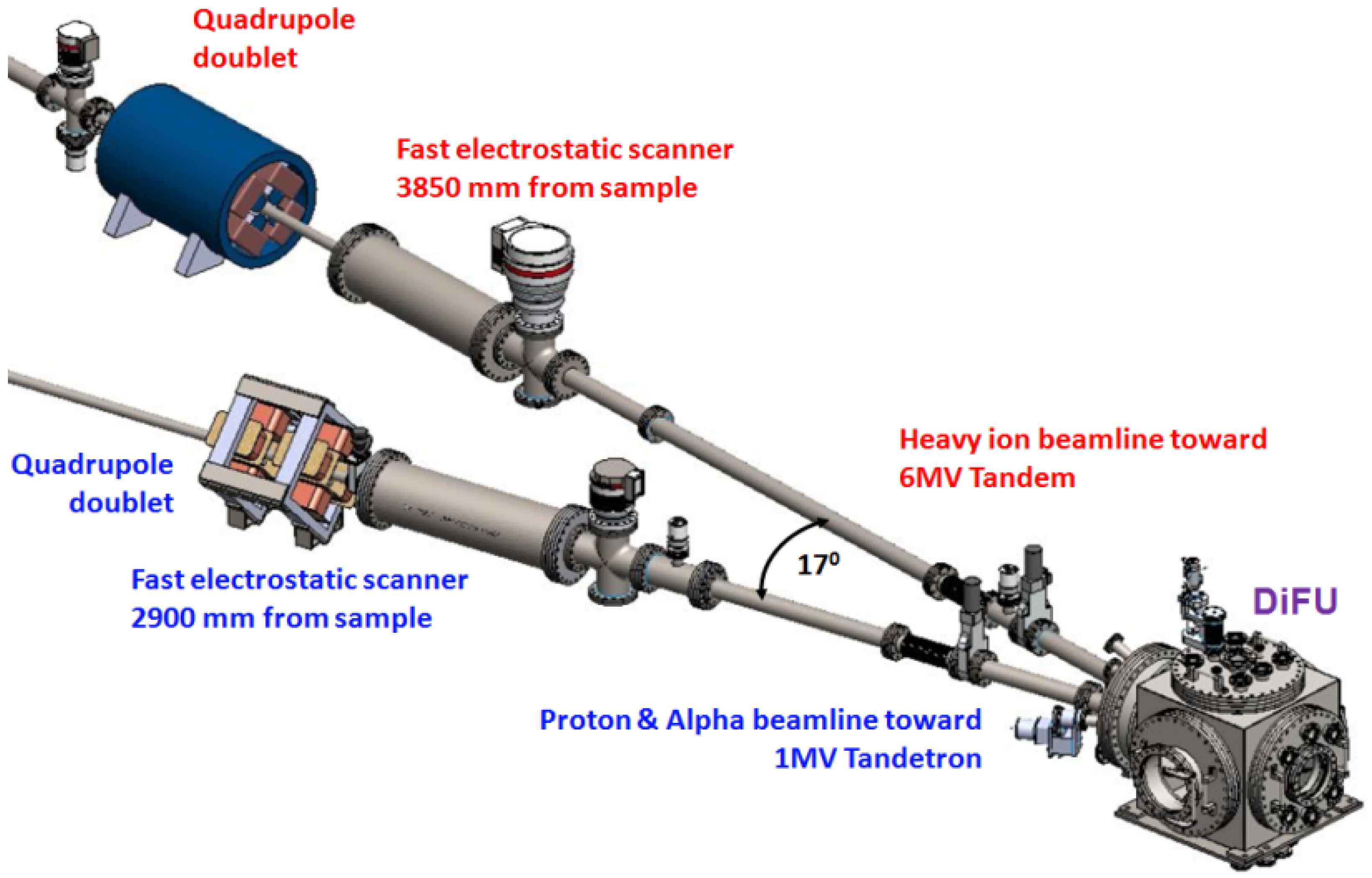
2.2. Ion Beam Handling
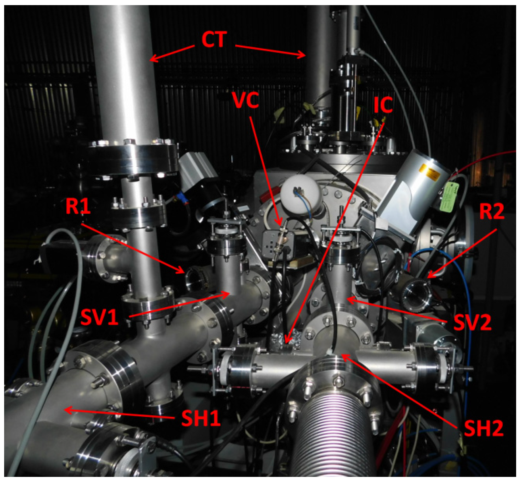
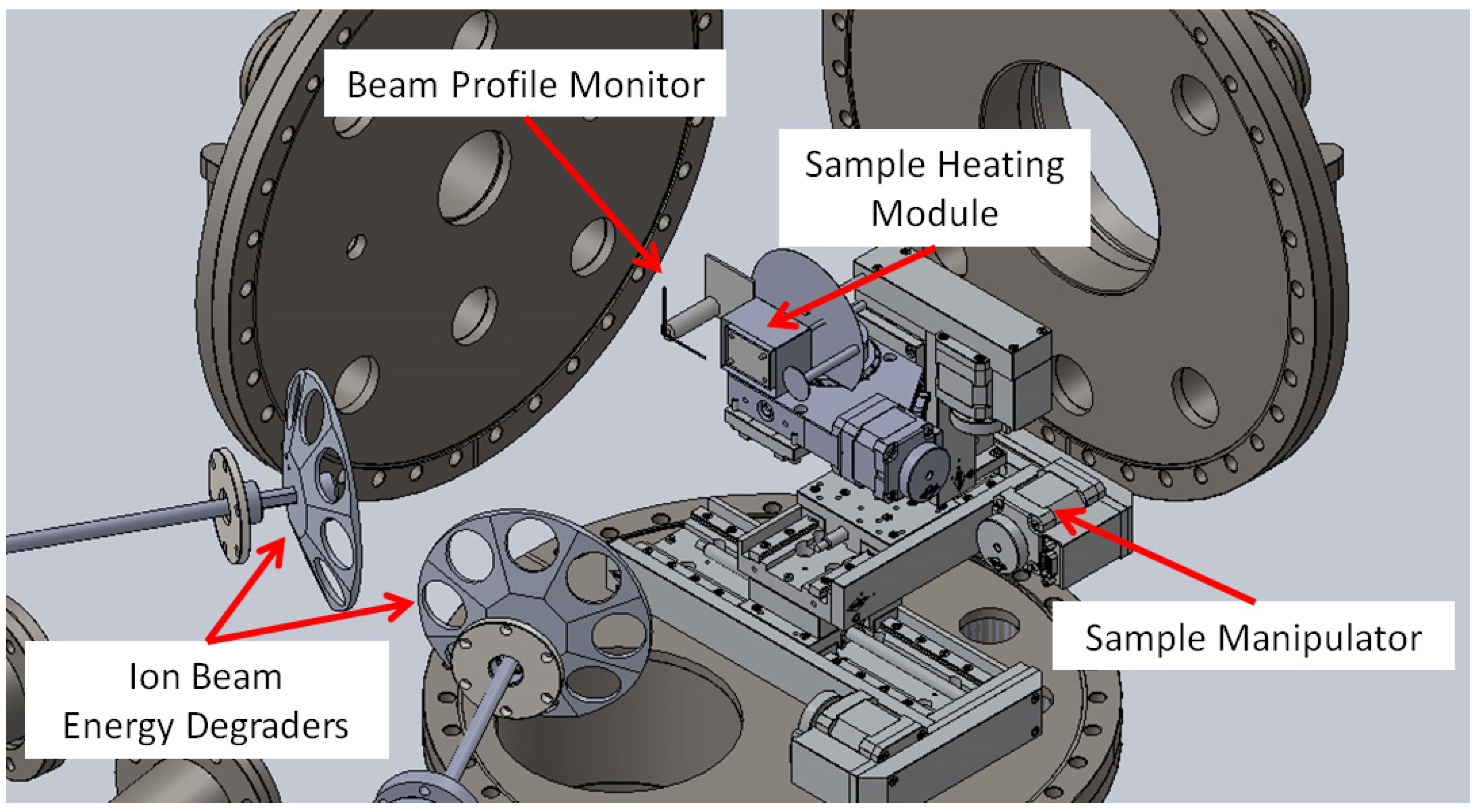
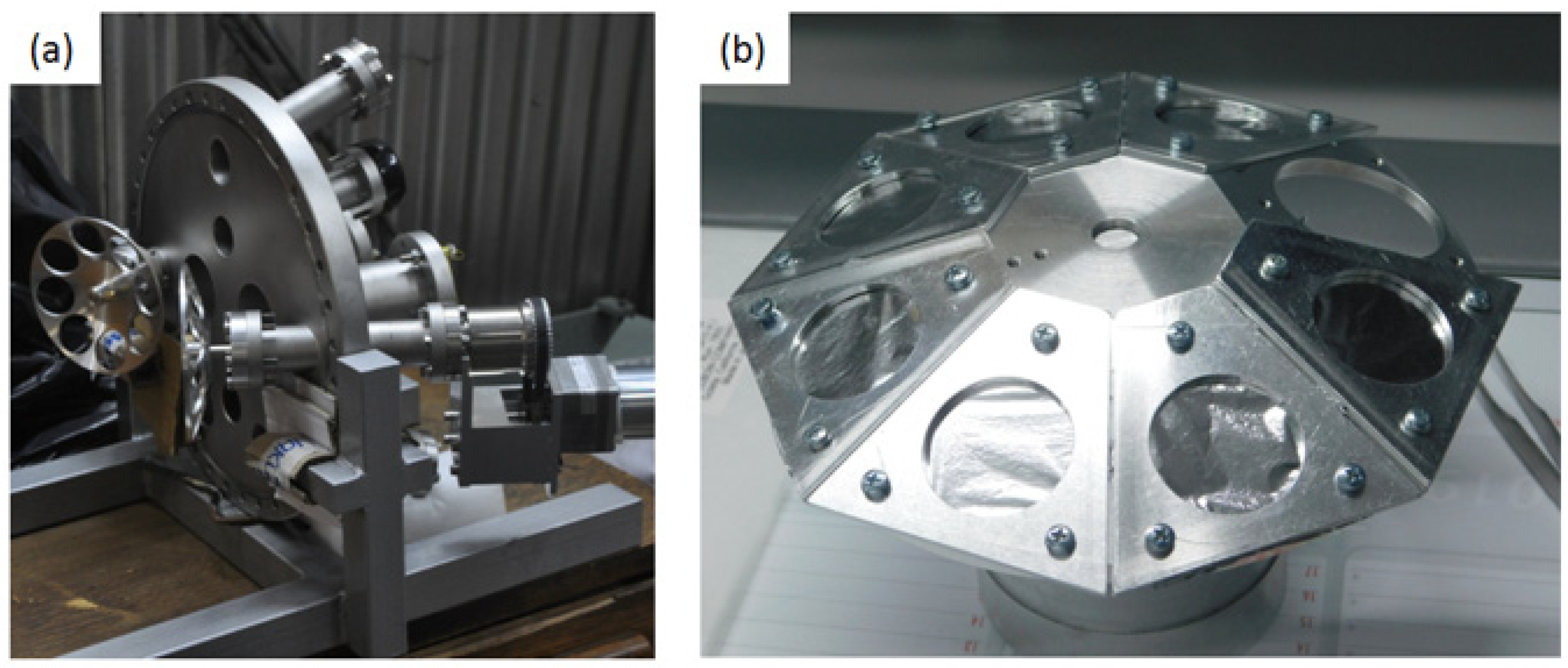
2.3. DiFU’s Irradiation Chamber
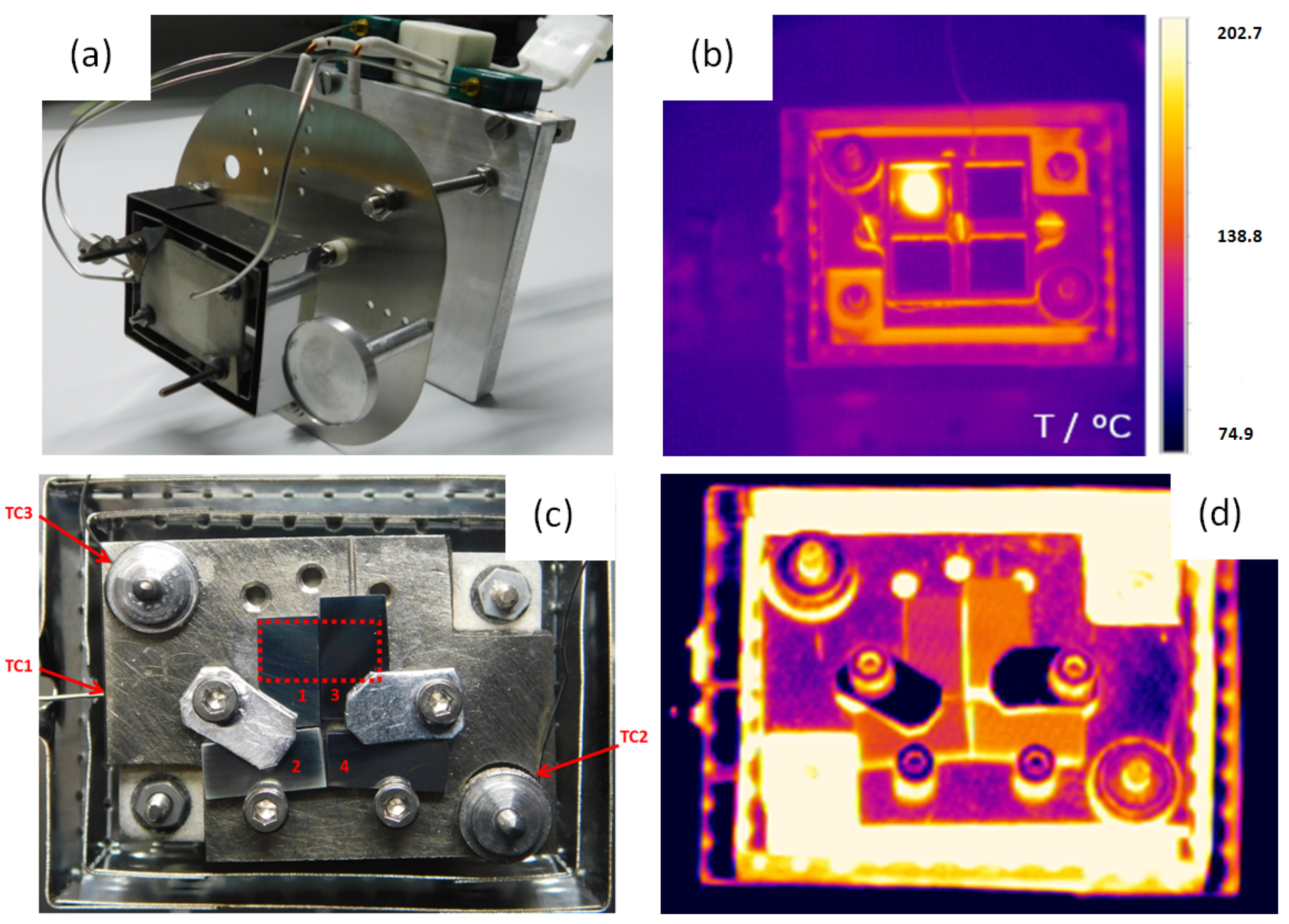
2.4. Sample Heating
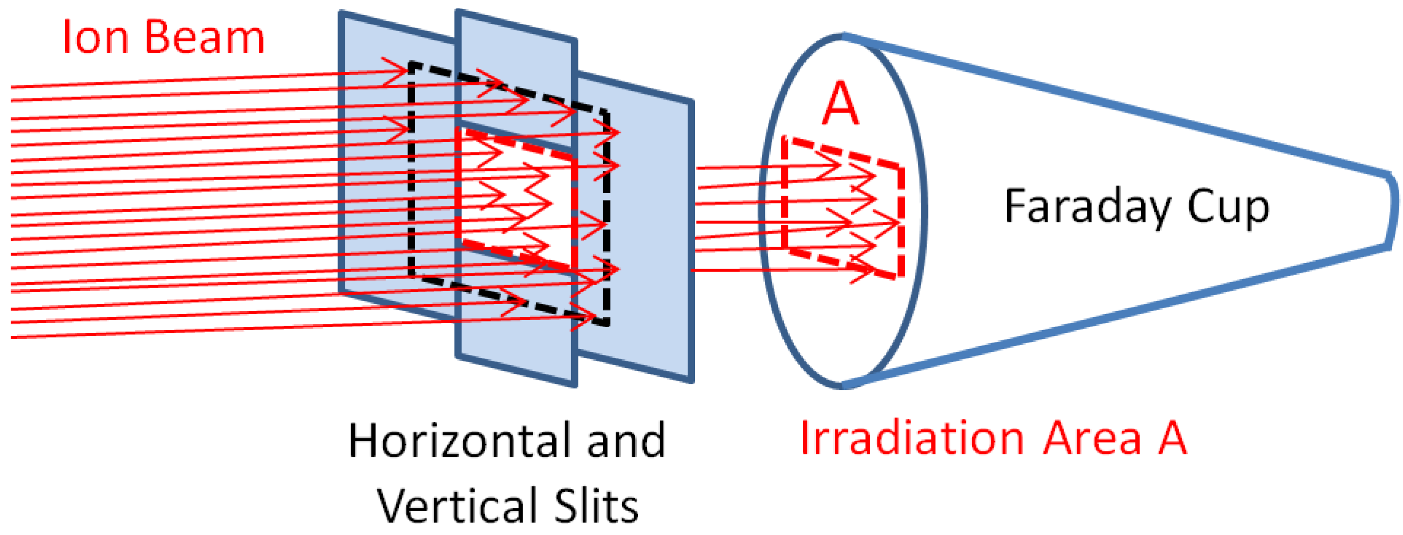
2.5. Ion Flux Estimation and Constant Ion Flux Monitoring
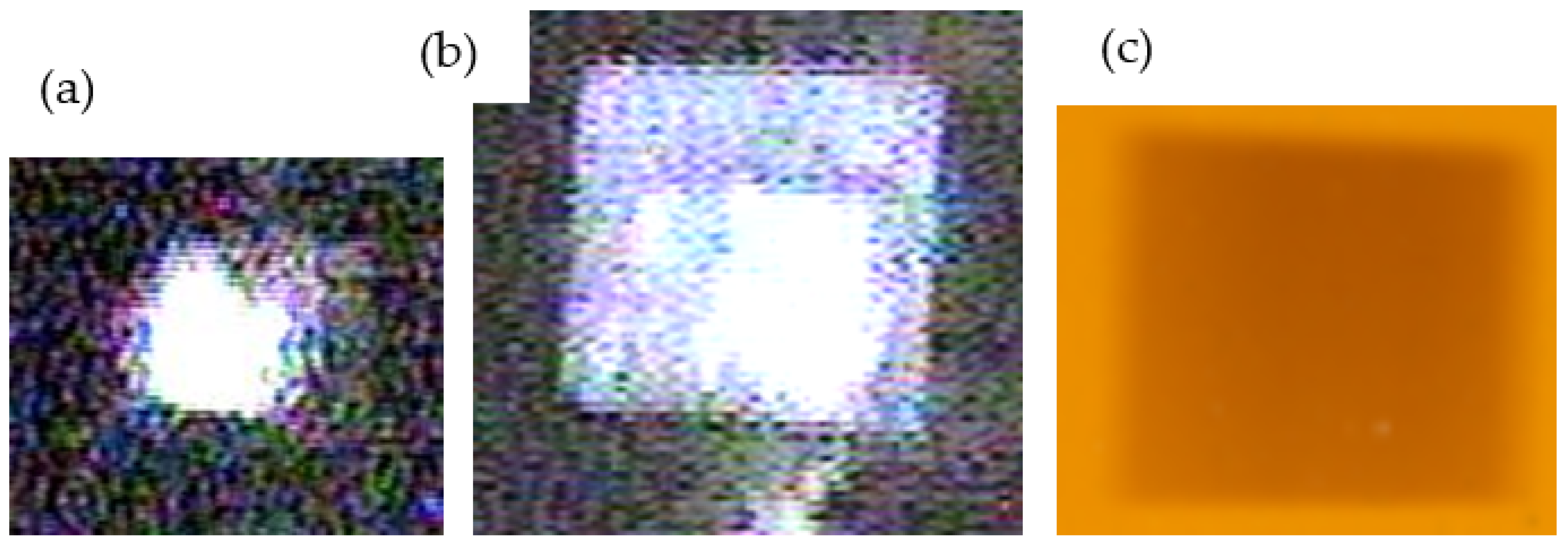
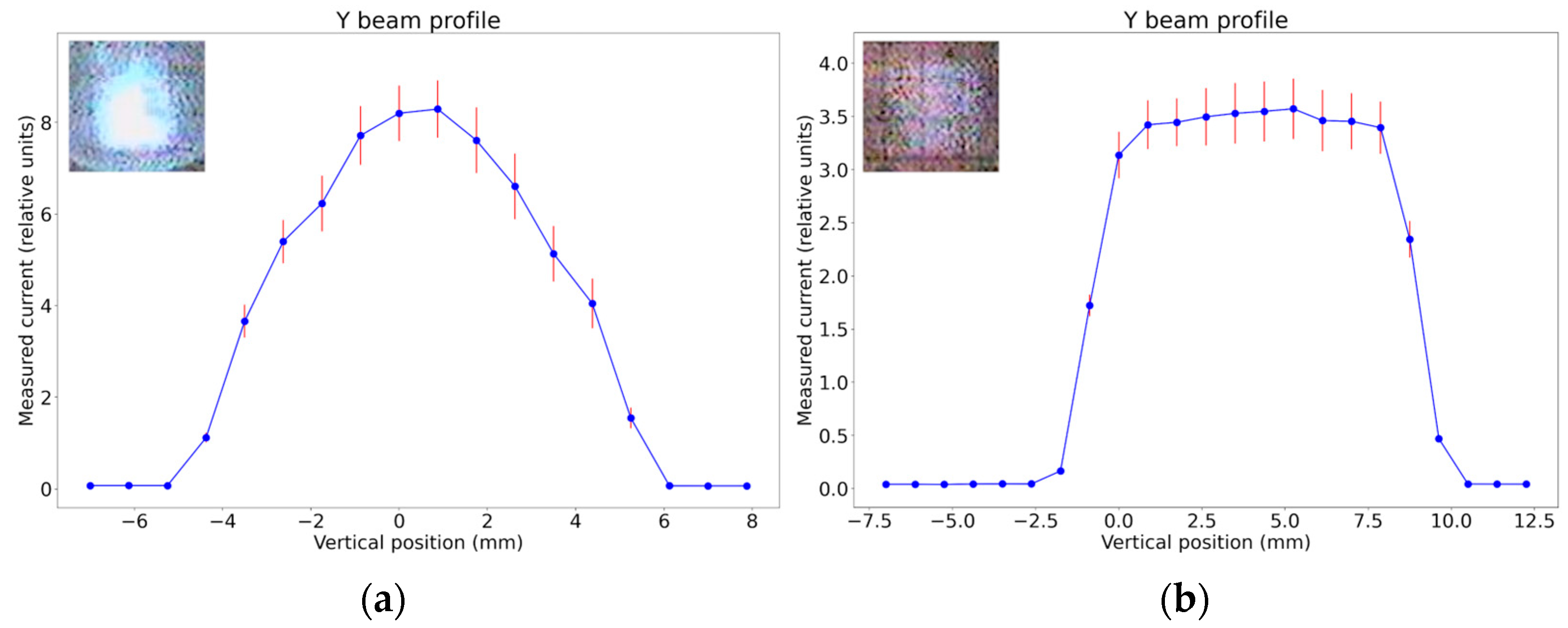
2.6. Homogeneity of Irradiation
2.7. Adjusting of Ion Energy
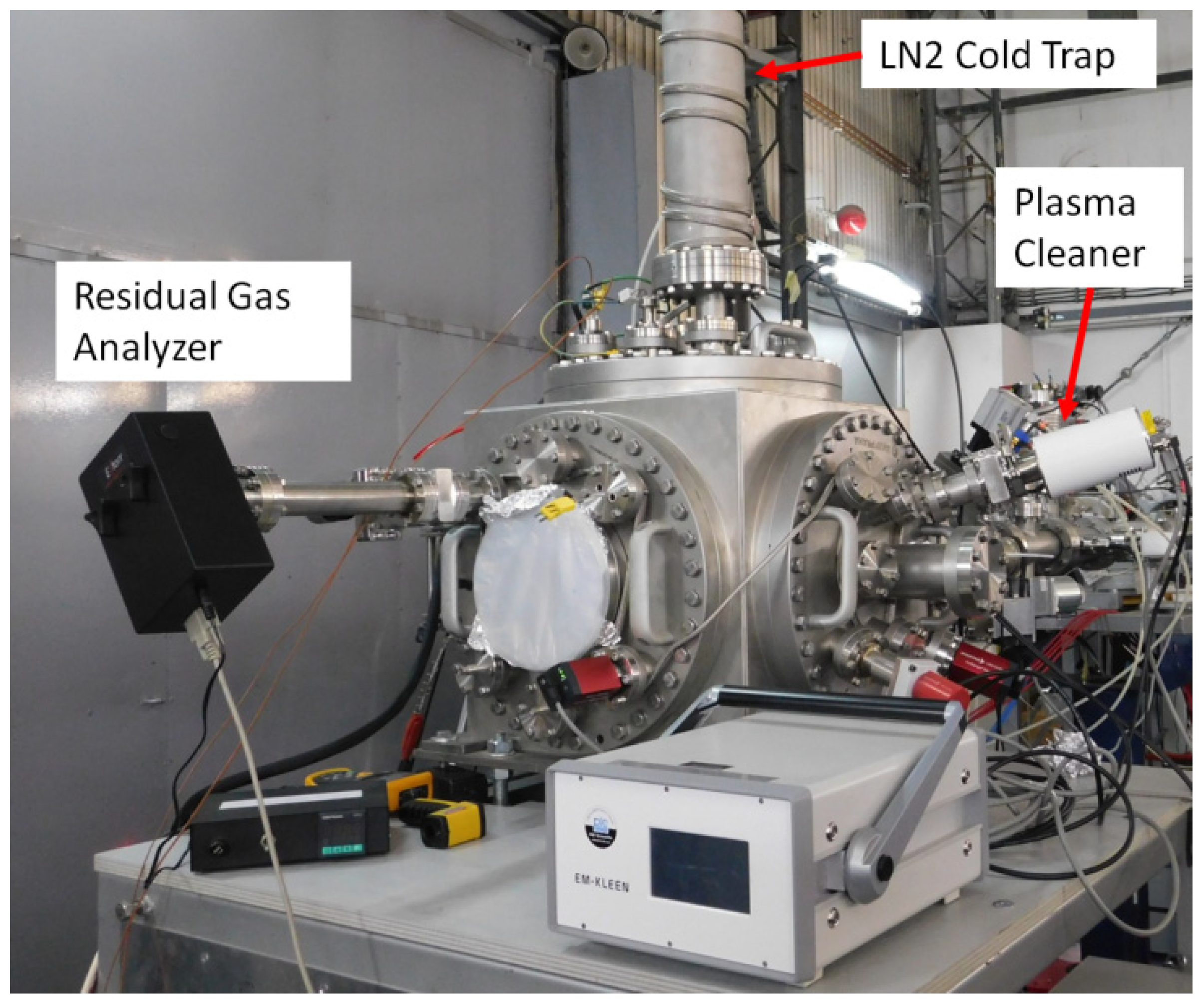
2.8. Mitigation of Carbon Contamination in the Vicinity of the Irradiated Sample
3. Results and Discussion
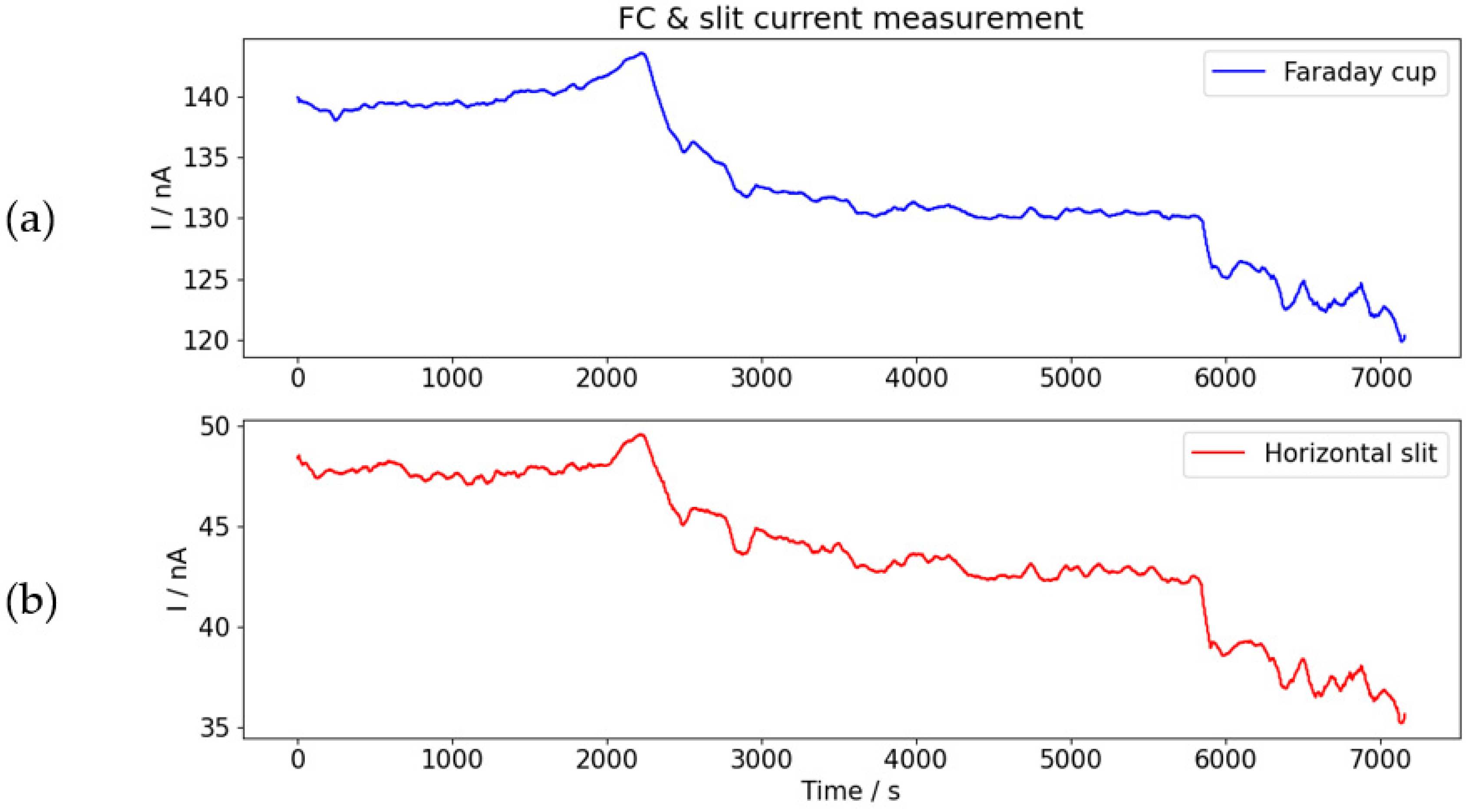
3.1. Testing of Ion Flux and Flux Fluctuations
3.2. Determination of Ion Beam Profile Homogeneity
3.3. Stability of Sample Temperature
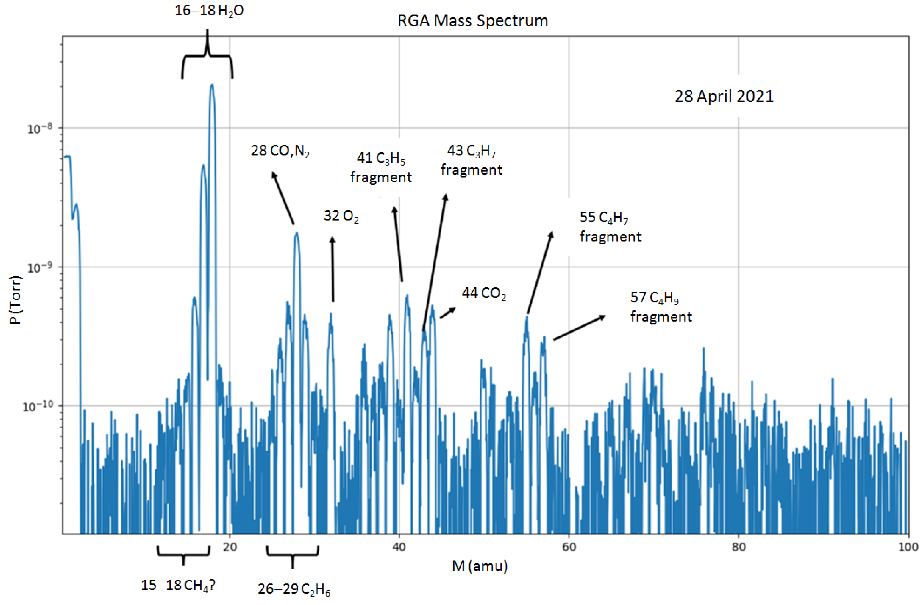
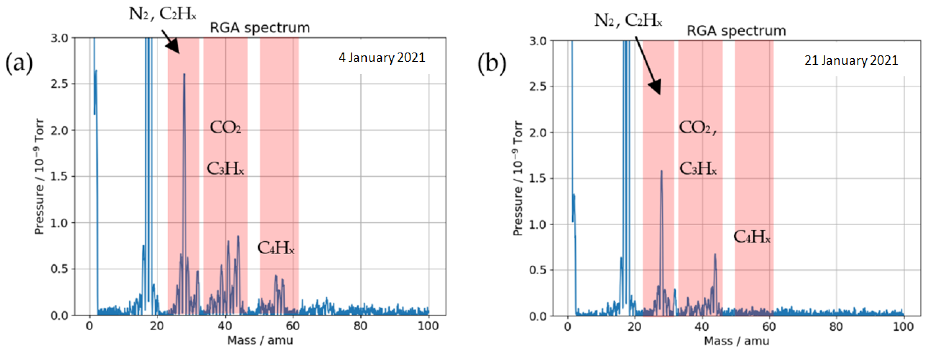
3.4. Residual Gases’ Composition
4. Summary
- Irradiation of samples by single-and dual-ion beams on areas from 5 × 5 to 30 × 30 mm2;
- Electrostatic ion beam scanning;
- Adjustment of ion energy by foil degraders;
- Indirect ion beam profile/ion beam flux measurement and constant ion flux monitoring from slits;
- Three-dimensional sample positioning using a sample manipulator;
- Heating of sample and control of sample temperature by IR camera and thermocouples;
- Mitigated deposition of hydrocarbons on the irradiated area of the sample; and
- Installation of additional equipment brought or asked by users.
Author Contributions
Funding
Institutional Review Board Statement
Informed Consent Statement
Data Availability Statement
Acknowledgments
Conflicts of Interest
References
- Trocellier, P.; Serruys, Y.; Miro, S.; Bordas, E.; Pellegrino, S.; Vaubaillon, S.; Ruault, M.; Henry, S.; Kaitasov, O. Application of multi-irradiation facilities. Nucl. Instrum. Methods B 2008, 266, 3178. [Google Scholar] [CrossRef]
- Kaschny, J.; Kogler, R.; Tyrrof, H.; Burger, W.; Eichhorn, F.; Mucklich, A.; Serre, C.; Skorupa, W. Facility for simultaneous dual-beam ion implantation. Nucl. Instrum. Methods A 2005, 551, 200. [Google Scholar] [CrossRef]
- Breeger, B.; Wendler, E.; Trippensee, W.; Schubert, C.; Wesch, W. Two-beam irradiation chamber for in situ ion-implantation and RBS at temperatures from 15 K to 300 K. Nucl. Instrum. Methods B 2001, 174, 199. [Google Scholar] [CrossRef]
- Kohyama, A.; Katoh, Y.; Jimbo, K. Radiation damage study by advanced dual-ion irradiation methods. Mater. Trans. 2004, 45, 51. [Google Scholar] [CrossRef][Green Version]
- Hamada, S.; Miwa, Y.; Yamaki, D.; Katano, Y.; Nazakawa, T.; Noda, K.J. Development of a triple beam irradiation facility. Nucl. Mater. 1998, 258–263, 383–387. [Google Scholar] [CrossRef]
- Kohyama, A.; Katoh, Y.; Ando, M.; Jimbo, K. A new Multiple Beams–Material Interaction Research Facility for radiation damage studies in fusion materials. Fusion Eng. Des. 2000, 51–52, 789–795. [Google Scholar] [CrossRef]
- Roldán, M.; Galán, P.; Sánchez, F.; García-Cortés, I.; Jiménez-Rey, D.; Fernández, P. Ion Beam Experiments to Emulate Nuclear Fusion Environment on Structural Materials at CMAM. Ion Beam Tech. Appl. 2019. [Google Scholar] [CrossRef]
- ASTM E521-16; Standard Practice for Investigating the Effects of Neutron Radiation Damage Using Charged-Particle Irradiation. ASTM: West Conshohocken, PA, USA, 2016. Available online: https://www.techstreet.com/standards/astm-e521-16?product_id=1937052 (accessed on 29 December 2022).
- Zinkle, S.J.; Snead, L. Opportunities and limitations for ion beams in radiation effects studies: Bridging critical gaps between charged particle and neutron irradiations. Scr. Mater. 2018, 143, 154–160. [Google Scholar] [CrossRef]
- Was, G.S. Challenges to the use of ion irradiation for emulating reactor irradiation. J. Mater. Res. 2015, 30, 1158–1182. [Google Scholar] [CrossRef]
- Simos, N.; Elbakhshwan, M.; Zhong, Z.; Ghose, S.; Savkliyildiz, I.J. High-temperature annealing of proton irradiated beryllium–A dilatometry-based study. Nucl. Mater. 2016, 477, 1–17. [Google Scholar] [CrossRef]
- Ammigan, K.; Amroussia, A.; Avilov, M.; Boehlert, C.; Calviani, M.; Casella, A.; Zwaska, R.M.; Densham, C.J.; Fornasiere, E.; Hurh, P.; et al. The RaDIATE high-energy proton materials irradiation experiment at the Brookhaven Linac Isotope Producer facility. In Proceedings of the 8th International Particle Accelerator Conference(IPAC2017), Copenhagen, Denmark, 14–19 May 2017; pp. 3593–3596. [Google Scholar]
- Johns, S.; Poulsen, T.; Kane, J.J.; Windes, W.E.; Ubic, R.; Karthik, C. Formation of carbon nanostructures in nuclear graphite under high-temperature in situ electron-irradiation. Carbon 2019, 143, 908–914. [Google Scholar] [CrossRef]
- Mironov, B.E.; Freeman, H.M.; Brown, A.P.; Hage, F.S.; Scott, A.J.; Westwood, A.V.K.; Da Costa, J.P.; Weisbecker, P.; Brydson, R.M.D. Electron irradiation of nuclear graphite studied by transmission electron microscopy and electron energy loss spectroscopy. Carbon 2015, 83, 106–117. [Google Scholar] [CrossRef]
- Knaster, J.; Moeslang, A.; Muroga, T. Materials research for fusion. Nat. Phys. 2016, 12, 424–434. [Google Scholar] [CrossRef]
- Was, G.S. Fundamentals of Radiation Materials Science: Metals and Alloys; Springer: Berlin/Heidelberg, Germany, 2016. [Google Scholar]
- Mayer, M.; Möller, S.; Rubel, M.; Widdowson, A.; Charisopoulos, S.; Ahlgren, T.; Alves, E.; Apostolopoulos, G.; Barradas, N.P.; Donnelly, S.; et al. Ion beam analysis of fusion plasma-facing materials and components: Facilities and research challenges. Nucl. Fusion 2019, 60, 025001. [Google Scholar] [CrossRef]
- Fazinić, S.; Božičević-Mihalić, I.; Provatas, G.; Tadić, T.; Rubel, M.; Fortuna-Zaleśna, E.; Widdowson, A. Micro-analyses of dust particles generated in the JET tokamak with the ITER-like wall. Nucl. Fusion 2020, 60, 126031. [Google Scholar] [CrossRef]
- Fazinic, S.; Tadic, T.; Vuks, M.; Rubel, M.; Petersson, P.; Fortuna-Zales, E.; Widdowson, A. Ion Microbeam Analyses of Dust Particles and Codeposits from JET with the ITER-Like Wall. Anal. Chem. 2018, 90, 5744–5752. [Google Scholar] [CrossRef] [PubMed]
- El-Atwani, O.; Cunningham, W.S.; Trelewicz, J.R.; Li, M.; Wirth, B.; Maloy, S.A. Revealing the synergistic effects of sequential and simultaneous dual beam irradiations in tungsten via in-situ TEM. J. Nucl. Mater. 2020, 538, 152150. [Google Scholar] [CrossRef]
- Hardie, C.D.; London, A.; Lim, J.; Bamber, R.; Tadić, T.; Vukšić, M.; Fazinić, S. Exploitation of thermal gradients for investigation of irradiation temperature effects with charged particles. Nat. Sci. Rep. 2019, 9, 13541. [Google Scholar] [CrossRef]
- Cookson, J.A. Specimen damage by nuclear microbeams and its avoidance. Nucl. Instrum. Methods B 1988, 30, 324–330. [Google Scholar] [CrossRef]
- Cahill, A.T.; McColm, D.W.; Kusko, B.H. Control of temperature in thin samples during ion beam analysis. Nucl. Instrum. Methods B 1986, 14, 38–44. [Google Scholar] [CrossRef]
- Crespillo, L.M.; Graham, J.T.; Zhang, Y.; Weber, W.J. Temperature measurements during high flux ion beam irradiations. Rev. Sci. Instrum. 2016, 87, 024902. [Google Scholar] [CrossRef]
- McColm, W.D.; Cahill, T.A. The temperature profile of a microprobe. Nucl. Instrum. Methods B 1991, 54, 91–97. [Google Scholar] [CrossRef]
- Ziegler, J.; Ziegler, M.D.; Biersack, J.P. SRIM–The stopping and range of ions in matter (2010). Nucl. Instrum. Methods B 2010, 268, 1818–1823. [Google Scholar] [CrossRef]
- Stoller, R.E.; Toloczko, M.B.; Was, G.S.; Certain, A.G.; Dwaraknath, S.; Garner, F.A. On the use of SRIM for computing radiation damage exposure. Nucl. Instrum. Methods B 2013, 310, 75–80. [Google Scholar] [CrossRef]
- Agarwal, S.; Lin, Y.; Li, C.; Stoller, R.E.; Zinkle, S.J. On the use of SRIM for calculating vacancy production: Quick calculation and full-cascade options. Nucl. Instrum. Methods B 2021, 503, 11–29. [Google Scholar] [CrossRef]
- Nastasi, M.; Wang, Y. Handbook of Modern Ion Beam Materials Analysis; CRC Press: Boca Raton, FL, USA, 2015; Chapter 16. [Google Scholar]
- Taller, S.; Naab, F.; Was, G.S. A methodology for customizing implantation profiles of light ions using a single thin foil energy degrader. Nucl. Instrum. Methods B 2020, 478, 274–283. [Google Scholar] [CrossRef]
- Sigmund, P.; Winterborn, K.B. Small-angle multiple scattering of ions in the screening Coulomb region: I. Angular distributions. Nucl. Instrum. Methods 1974, 119, 541. [Google Scholar] [CrossRef]
- Tadic, T.; Jaksic, M. Heavy ion microbeam vacuum requirements. Nucl. Instrum. Methods B 2009, 267, 2028–2031. [Google Scholar] [CrossRef]
- Jakšić, M.; Chokheli, D.; Fazinić, S.; Grilj, V.; Skukan, N.; Sudić, I.; Tadić, T.; Antičić, T. In-air ion beam analysis with high spatial resolution proton microbeam. Nucl. Instrum. Methods B 2016, 371, 185–188. [Google Scholar] [CrossRef]
- Healy, M.J.F. Minimising carbon contamination during ion beam analysis. Nucl. Instrum. Methods B 1997, 129, 130–136. [Google Scholar] [CrossRef]
- Mörschbächer, M.J.; Behar, M.J. Carbon deposition in Si as a consequence of H and He irradiations: A systematic study. Appl. Phys. 2002, 91, 6481–6487. [Google Scholar] [CrossRef]
- Was, G.S.; Taller, S.; Jiao, Z.; Monterrosa, A.; Woodley, D.; Jennings, D.; Kubley, T.; Naab, F.; Toader, O.; Uberseder, E. Resolution of the carbon contamination problem in ion irradiation experiments. Nucl. Instrum. Methods B 2017, 412, 58–65. [Google Scholar] [CrossRef]
- Yamashita, T.; Tanaka, Y.; Nagoshi, M.; Ishida, K. Novel technique to suppress hydrocarbon contamination for high accuracy determination of carbon content in steel by FE-EPMA. Sci. Rep. 2016, 6, 29825. [Google Scholar] [CrossRef] [PubMed]
- Viel, L.; Benazeth, C.; Benazeth, N. Spectres Auger sous bombardement d’ions Ar+ de 60 keV de quelques éléments purs et de composés binaires. Surf. Sci. 1976, 54, 635. [Google Scholar] [CrossRef]
- Gigax, J.G.; Kim, H.; Aydogan, E.; Garner, F.A.; Maloy, S.; Shao, L. Beam-contamination-induced compositional alteration and its neutron-atypical consequences in ion simulation of neutron-induced void swelling. Mater. Res. Lett. 2017, 5, 478–485. [Google Scholar] [CrossRef]
- Gigax, J.G.; Kim, H.; Aydogan, E.; Price, L.M.; Wang, X.; Maloy, S.A.; Garner, F.A.; Shao, L. Impact of composition modification induced by ion beam Coulomb-drag effects on the nanoindentation hardness of HT9. Nucl. Instrum. Methods B 2019, 444, 68–73. [Google Scholar] [CrossRef]
- Harris, N.S. Modern Vacuum Practice; McGraw-Hill International: New York, NY, USA, 1989. [Google Scholar]
- Ferré, G.F.; Mairov, A.; Ceseracciu, L.; Serruys, Y.; Trocellier, P.; Baumier, C.; Kaïtasov, O.; Brescia, R.; Gastaldi, D.; Vena, P.; et al. Radiation endurance in Al 2 O 3 nanoceramics. Sci. Rep. 2016, 6, 33478. [Google Scholar] [CrossRef]
- Angiolini, E.M.; Agostini, P.; Pilloni, L.; Utili, M.; Di Fonzo, F.; Ferré, F.G. International Conference on Fast Reactors and Related Fuel Cycles: Next Generation Nuclear Systems for Sustainable Development; IAEA: Vienna, Austria, 2017. [Google Scholar]


Disclaimer/Publisher’s Note: The statements, opinions and data contained in all publications are solely those of the individual author(s) and contributor(s) and not of MDPI and/or the editor(s). MDPI and/or the editor(s) disclaim responsibility for any injury to people or property resulting from any ideas, methods, instructions or products referred to in the content. |
© 2023 by the authors. Licensee MDPI, Basel, Switzerland. This article is an open access article distributed under the terms and conditions of the Creative Commons Attribution (CC BY) license (https://creativecommons.org/licenses/by/4.0/).
Share and Cite
Tadić, T.; Dunatov, T.; Fazinić, S.; Cosic, D.D.; Jakšić, M.; Siketić, Z.; Vićentijević, M.; Kada, W.; Hardie, C.D. Development of the Dual-Beam Ion Irradiation Facility for Fusion Materials (DiFU). Materials 2023, 16, 1144. https://doi.org/10.3390/ma16031144
Tadić T, Dunatov T, Fazinić S, Cosic DD, Jakšić M, Siketić Z, Vićentijević M, Kada W, Hardie CD. Development of the Dual-Beam Ion Irradiation Facility for Fusion Materials (DiFU). Materials. 2023; 16(3):1144. https://doi.org/10.3390/ma16031144
Chicago/Turabian StyleTadić, Tonči, Toni Dunatov, Stjepko Fazinić, Donny Domagoj Cosic, Milko Jakšić, Zdravko Siketić, Milan Vićentijević, Wataru Kada, and Christopher D. Hardie. 2023. "Development of the Dual-Beam Ion Irradiation Facility for Fusion Materials (DiFU)" Materials 16, no. 3: 1144. https://doi.org/10.3390/ma16031144
APA StyleTadić, T., Dunatov, T., Fazinić, S., Cosic, D. D., Jakšić, M., Siketić, Z., Vićentijević, M., Kada, W., & Hardie, C. D. (2023). Development of the Dual-Beam Ion Irradiation Facility for Fusion Materials (DiFU). Materials, 16(3), 1144. https://doi.org/10.3390/ma16031144