
Microwave Imaging Approach for Breast Cancer Detection Using a Tapered Slot Antenna Loaded with Parasitic Components

 , , ,
, , ,  ,
,  and
and 
Abstract
:1. Introduction
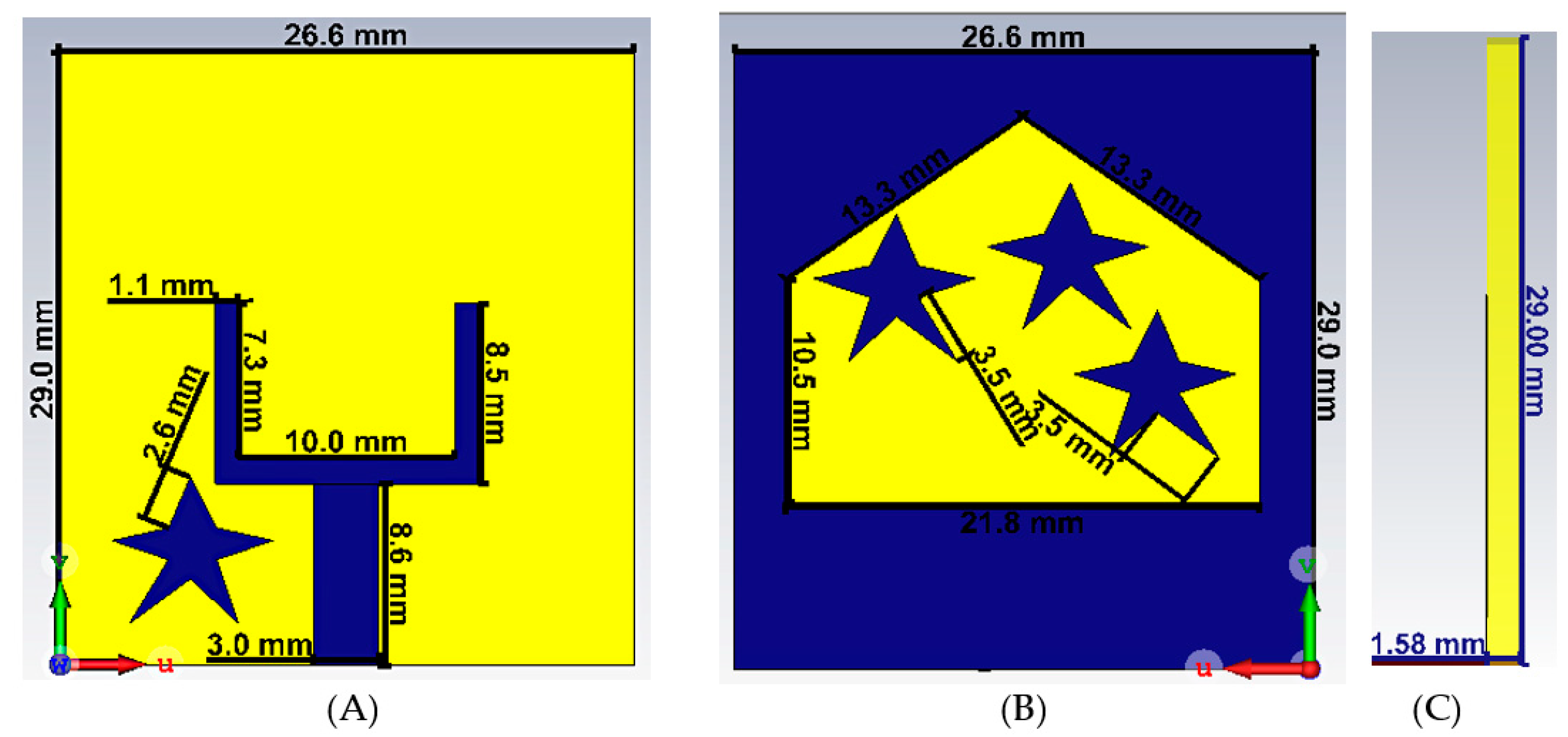
2. Antenna Design
3. Results and Discussion
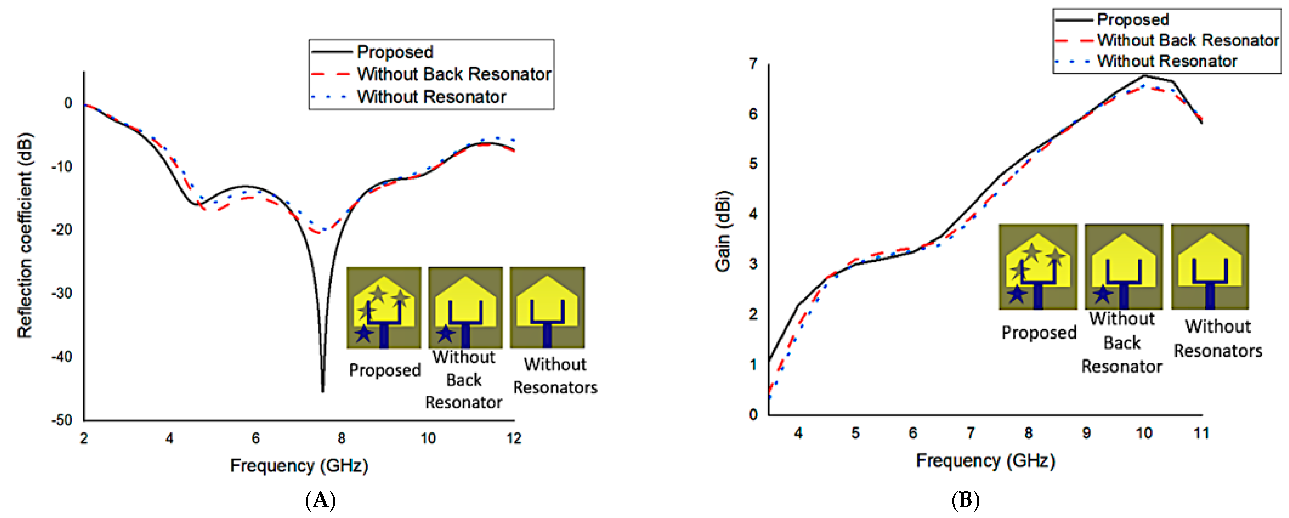
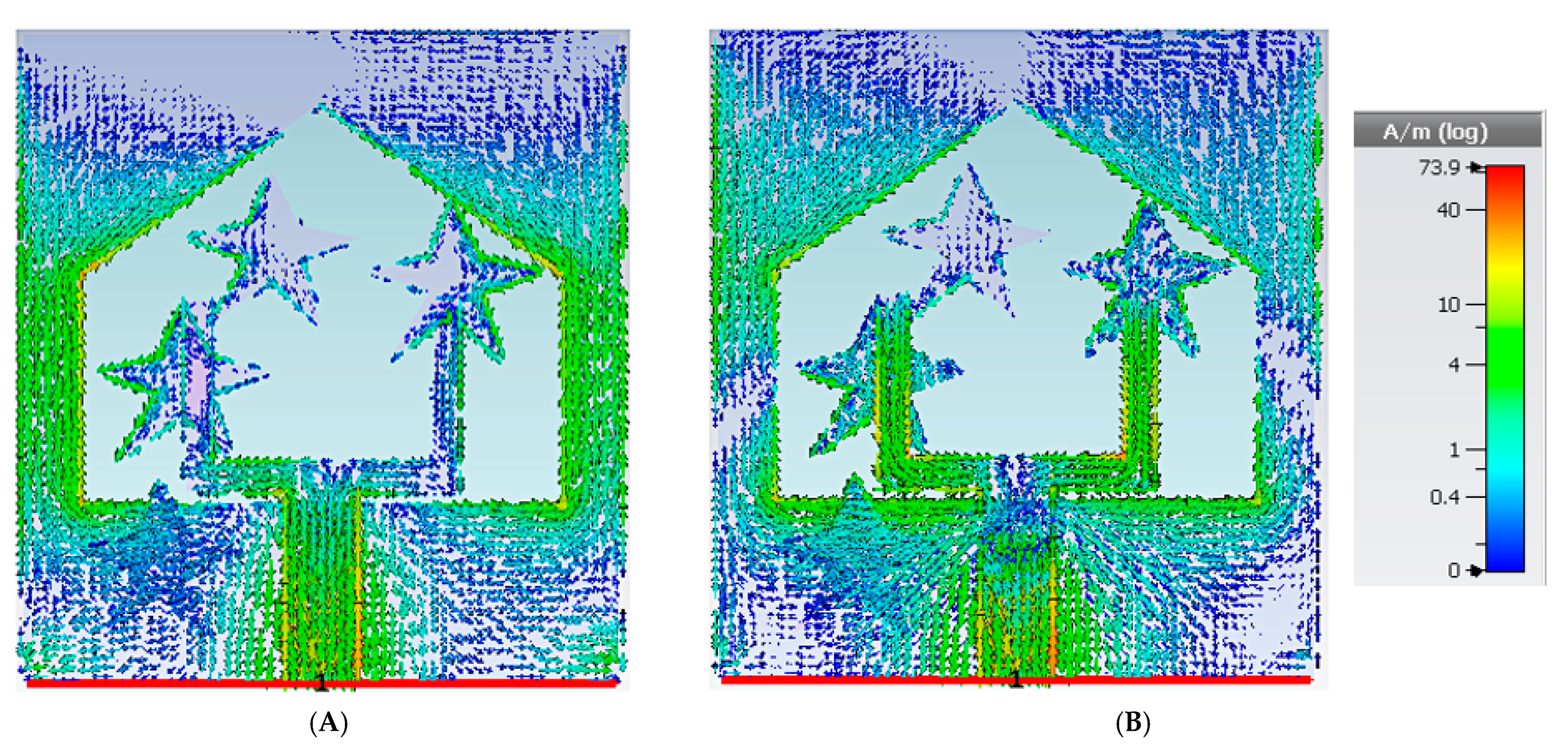
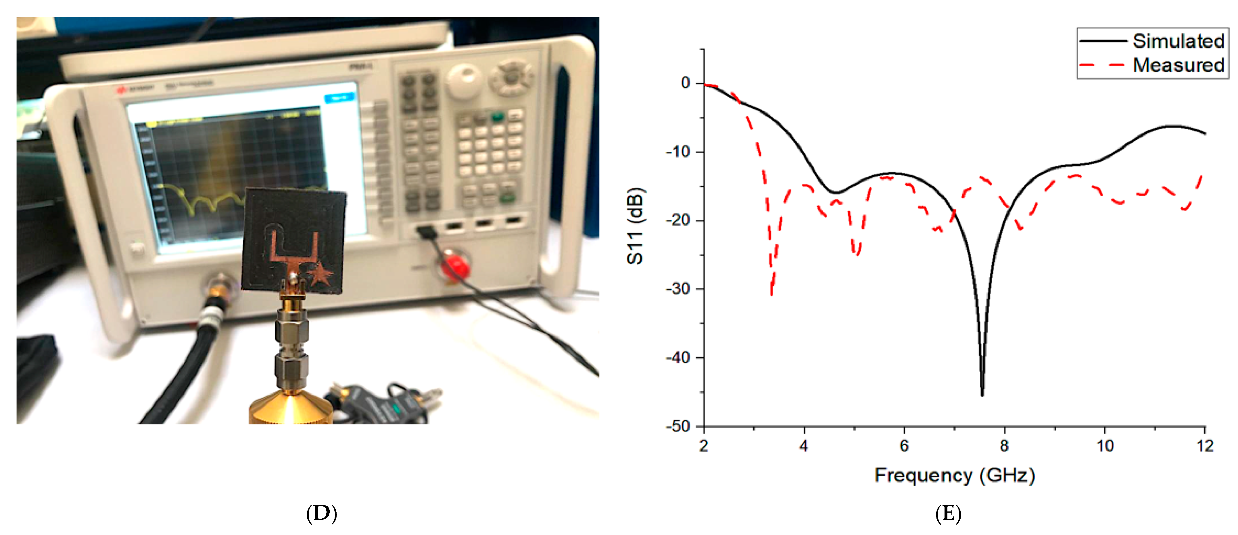
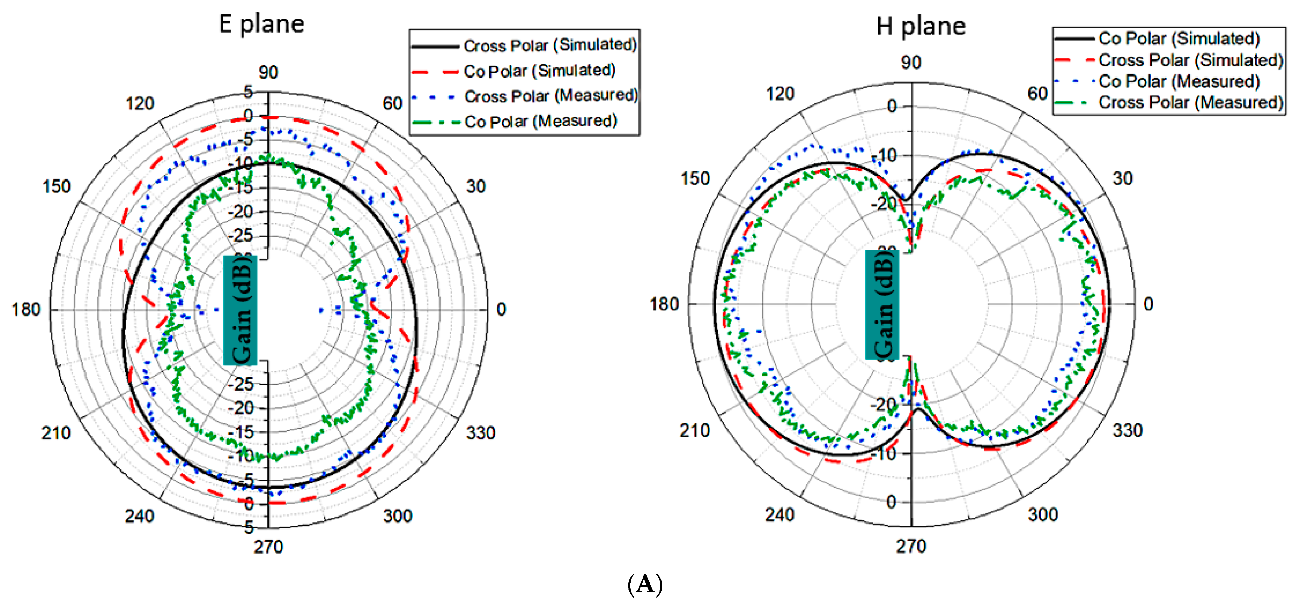
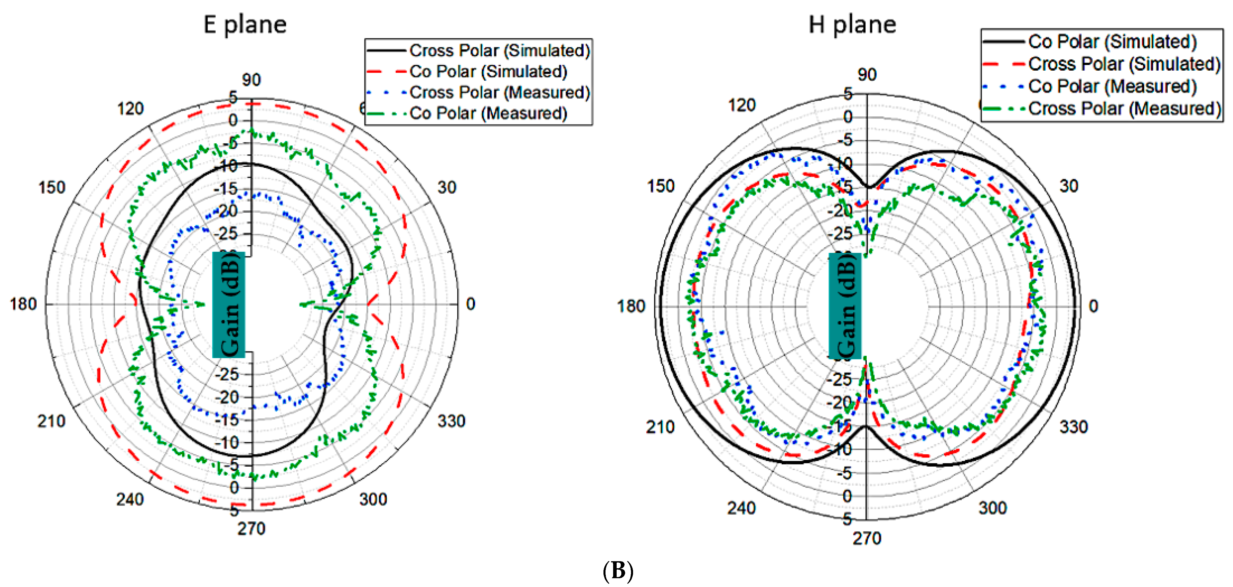
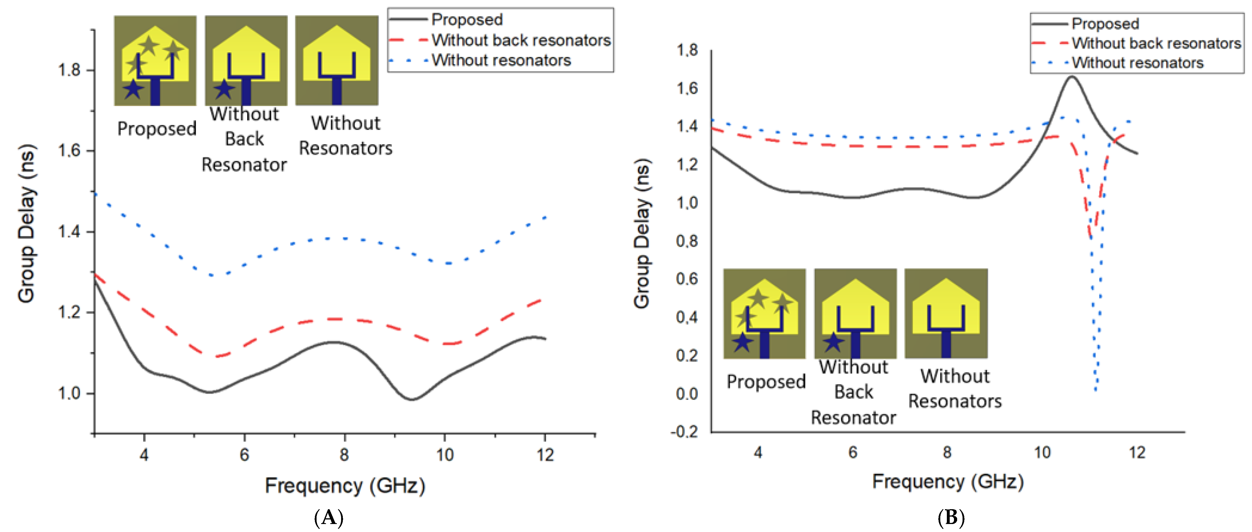
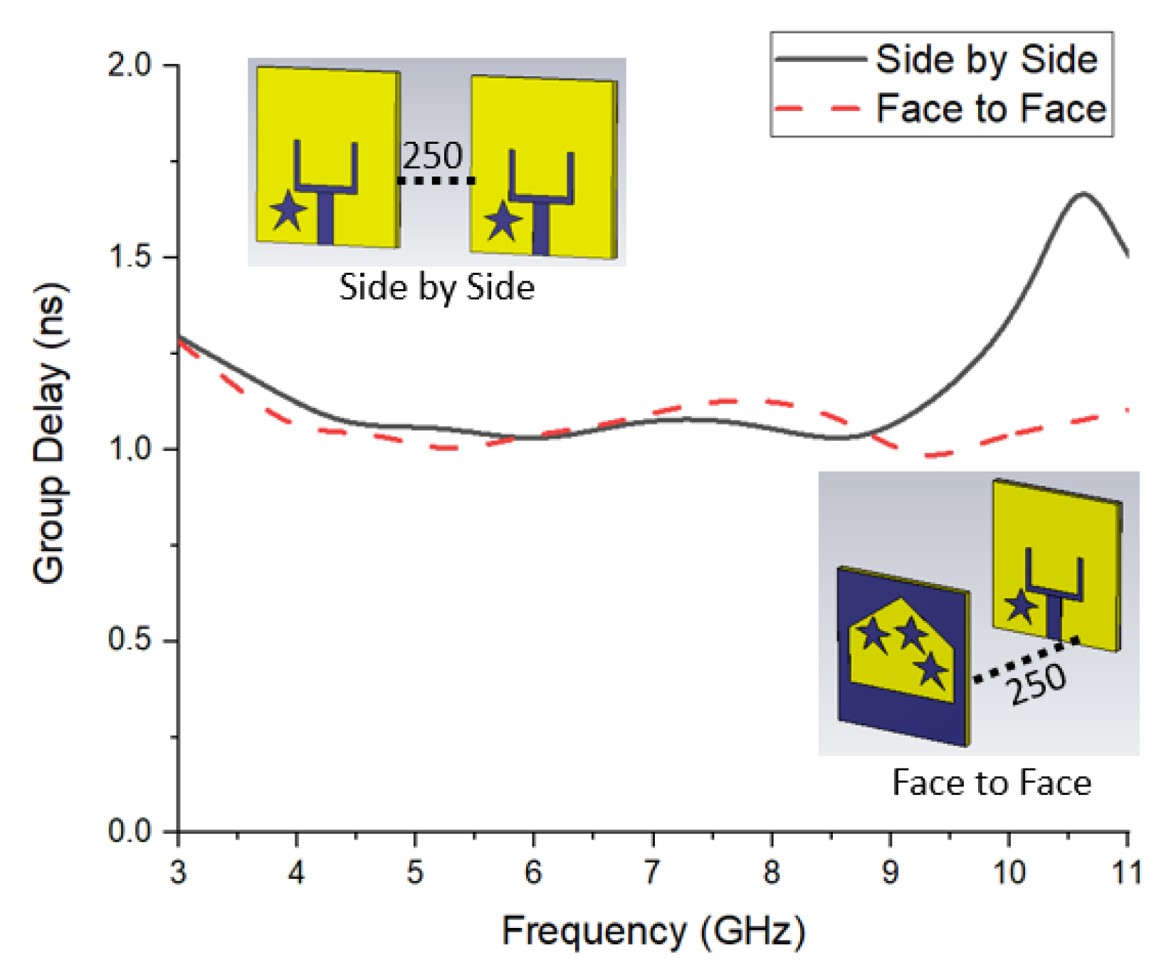
3.1. Frequency Domain
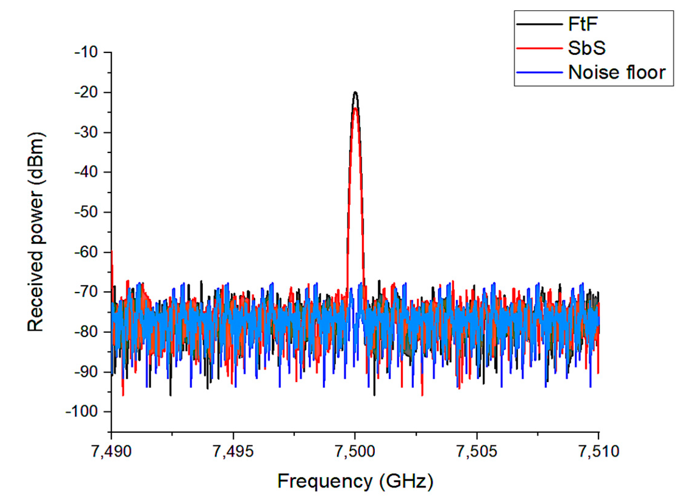
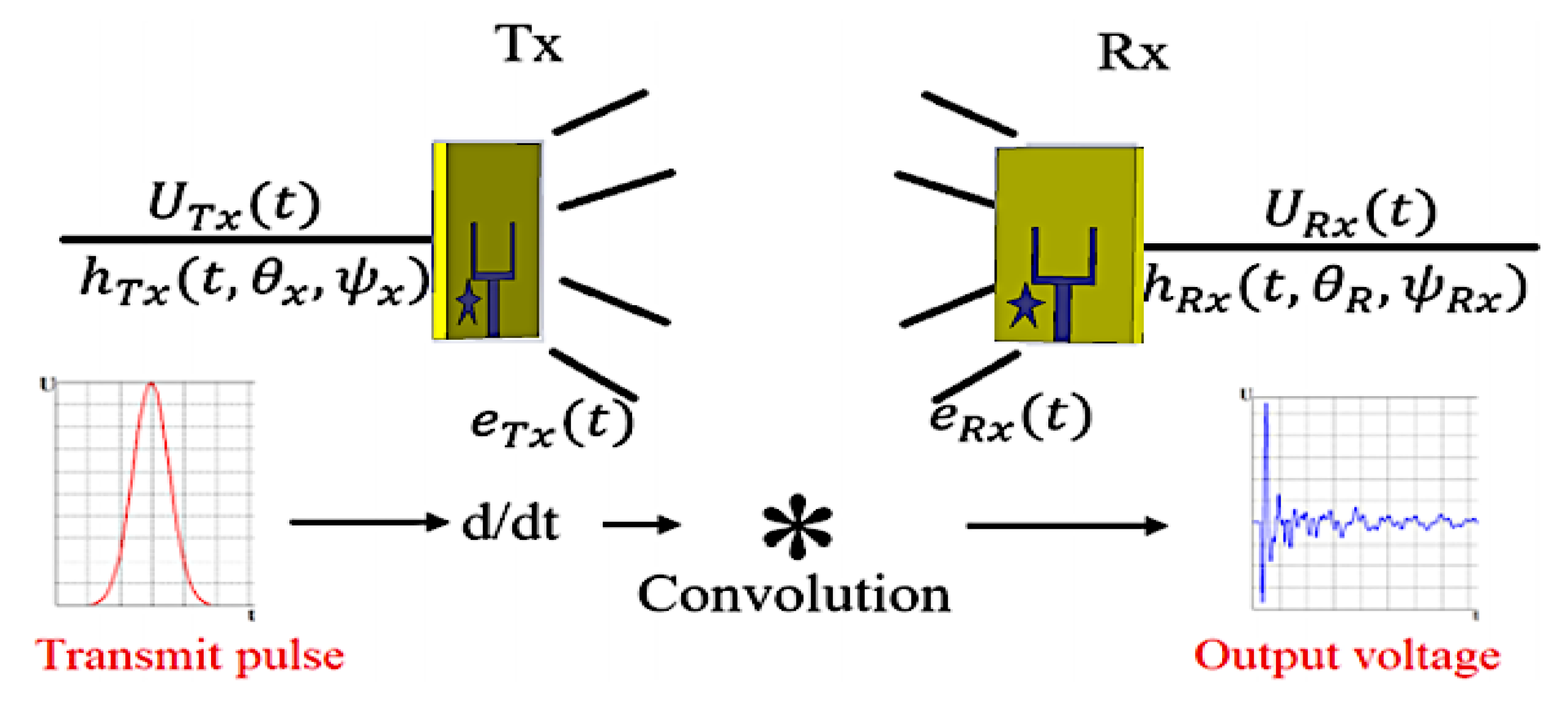
3.2. Time-Domain Performance
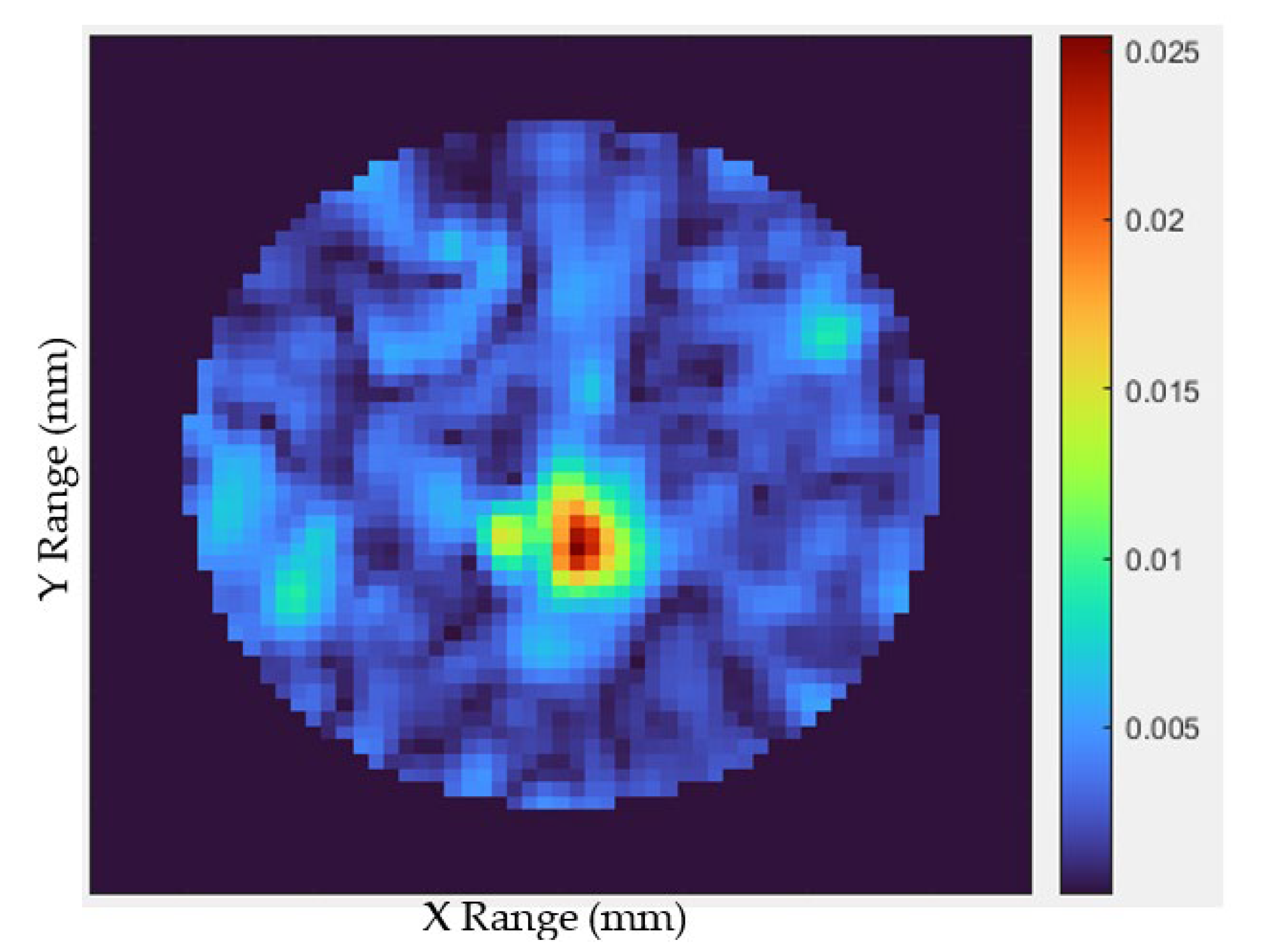
4. Microwave Imaging
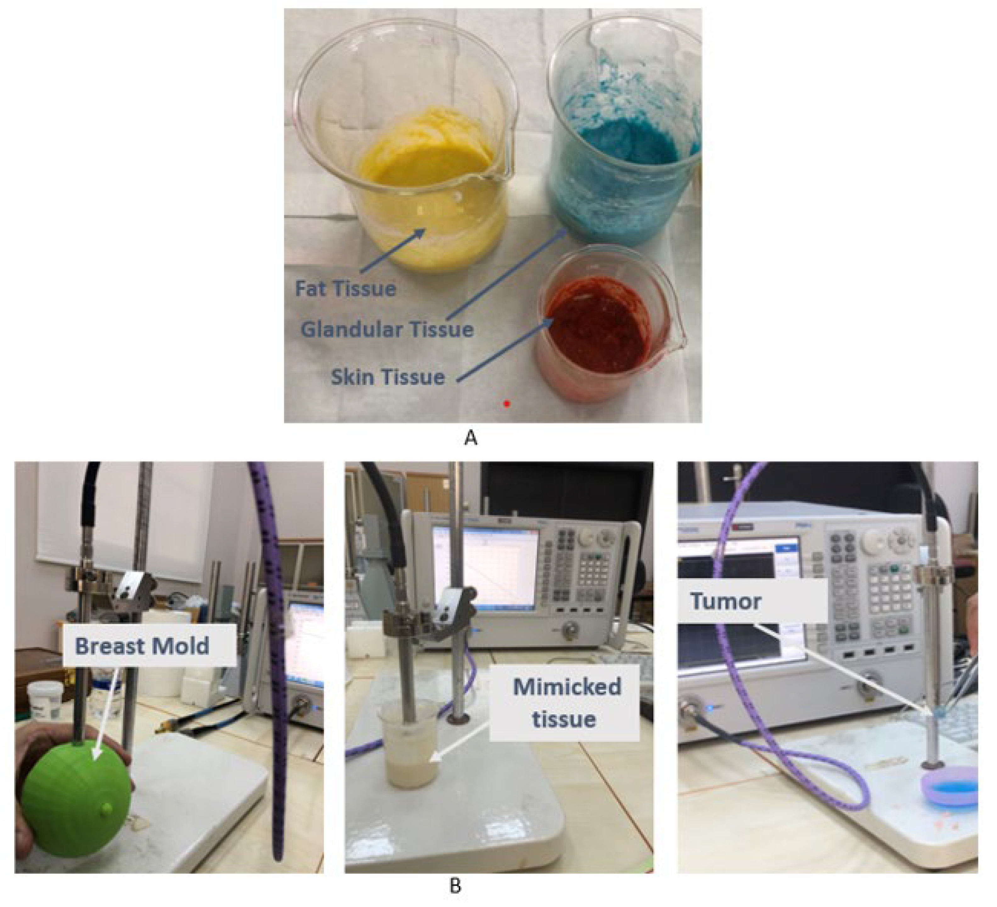
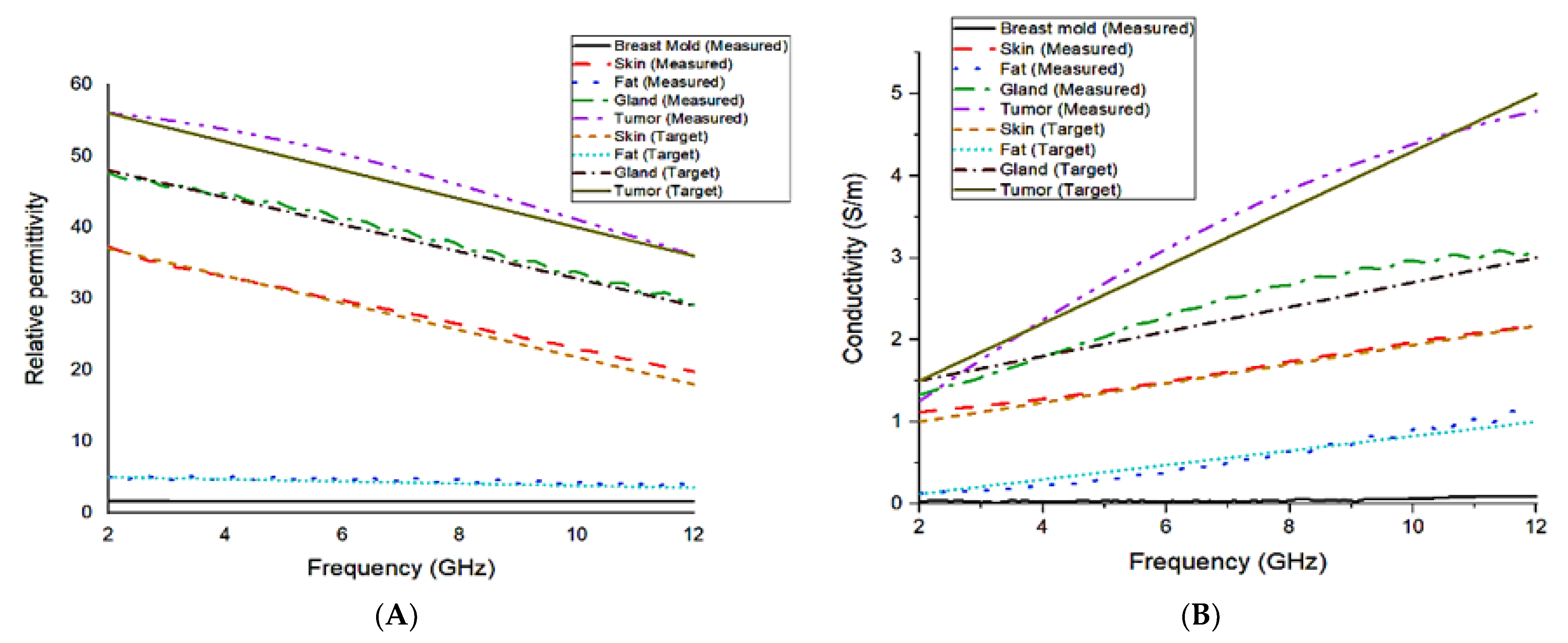
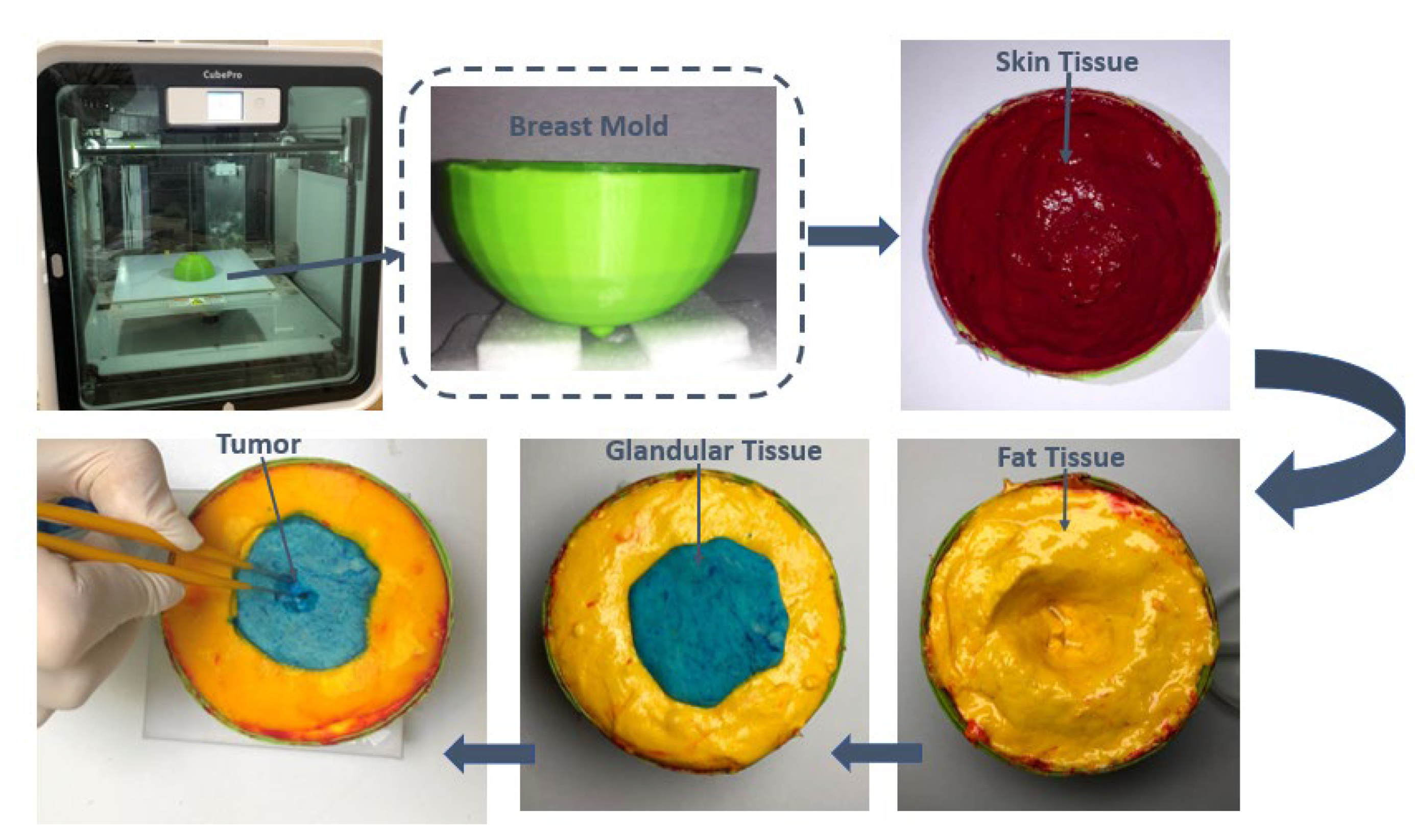
4.1. Fabrication of Heterogeneous Breast Phantom
- Step 1: Measure the quantity of material according to Table 2.
- Step 2: Add distilled water, oil and P.P.J to flour.
- Step 3: Add NaCl.
- Step 4: Add powder.
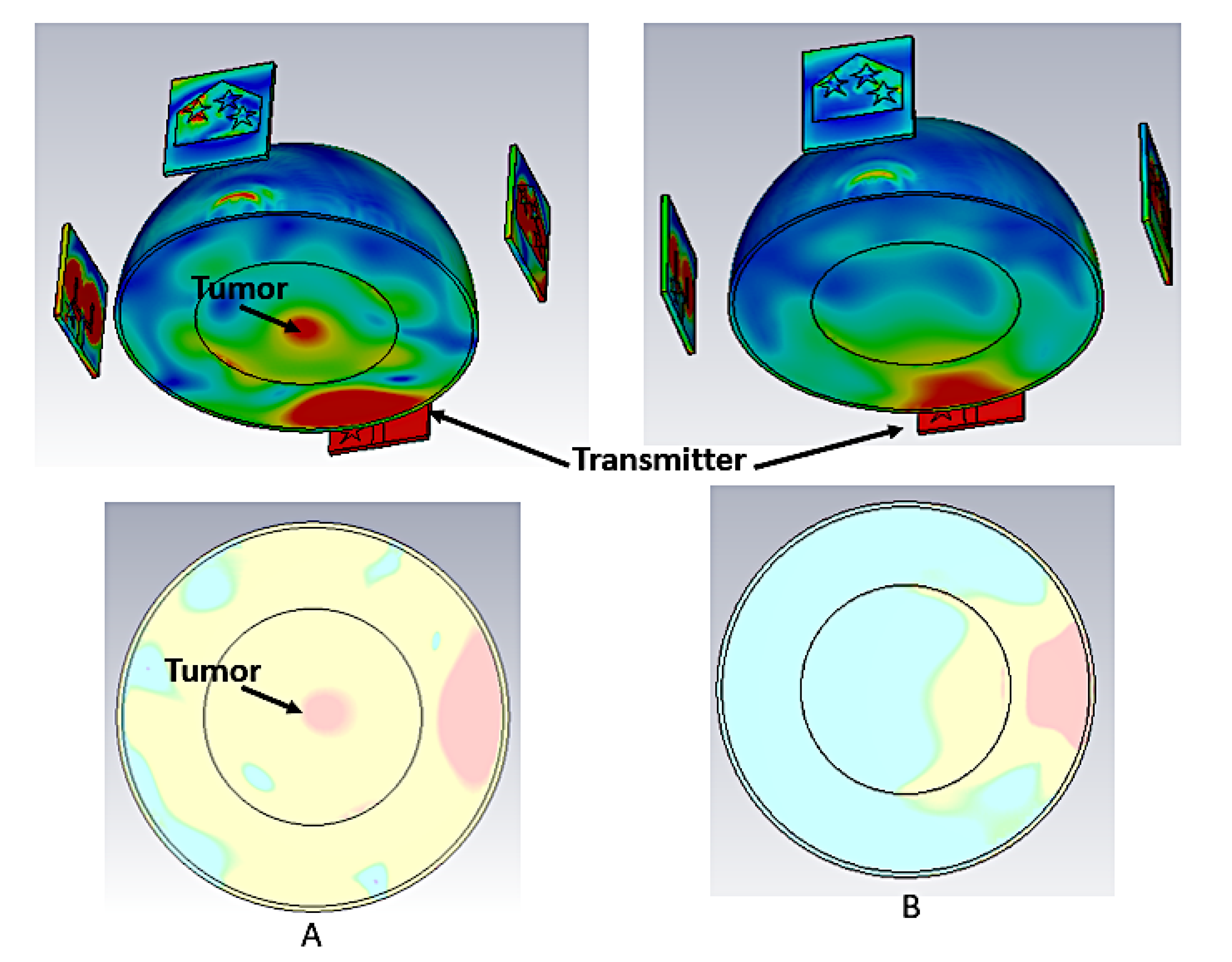
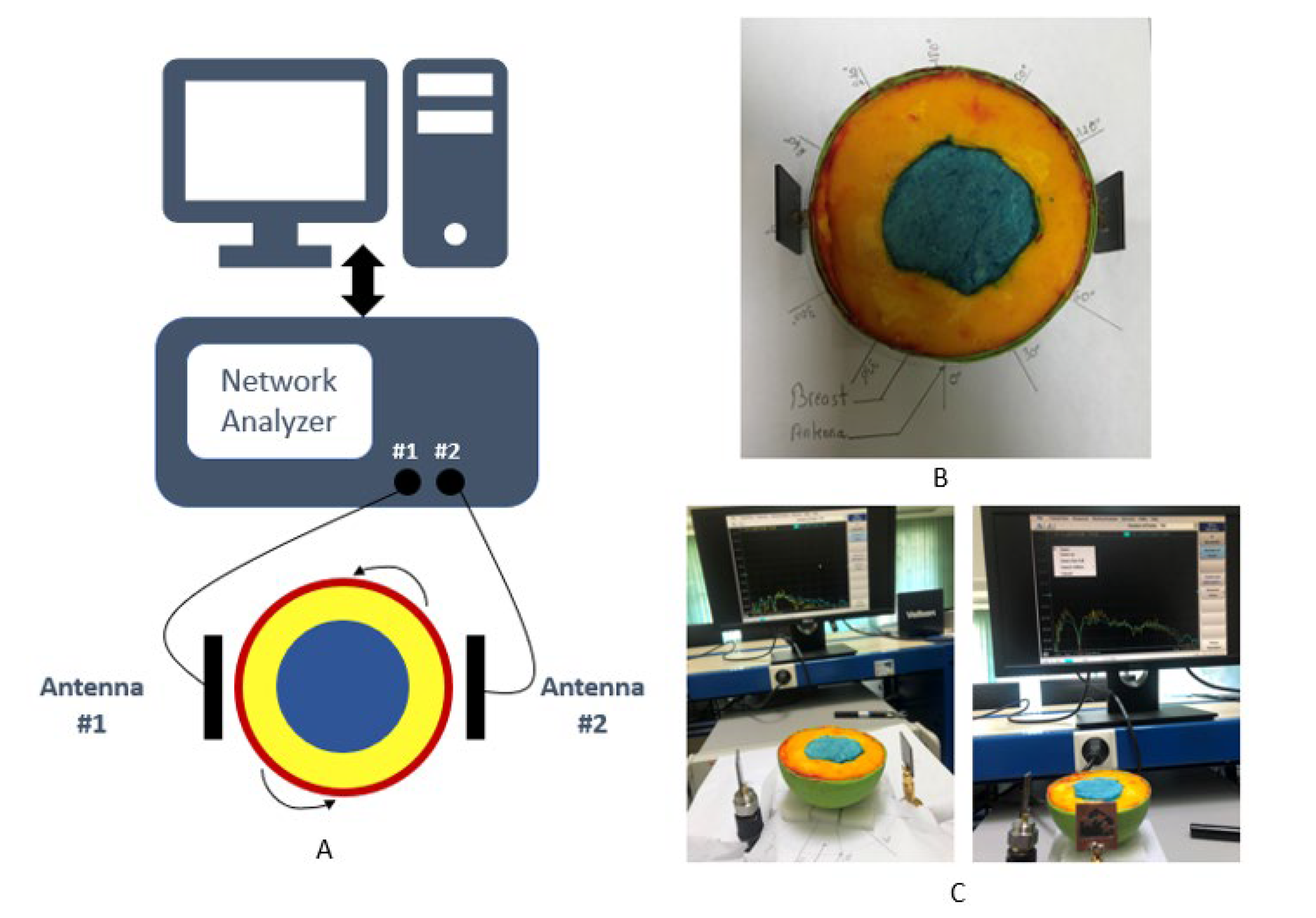
4.2. Microwave Imaging Simulated Setup
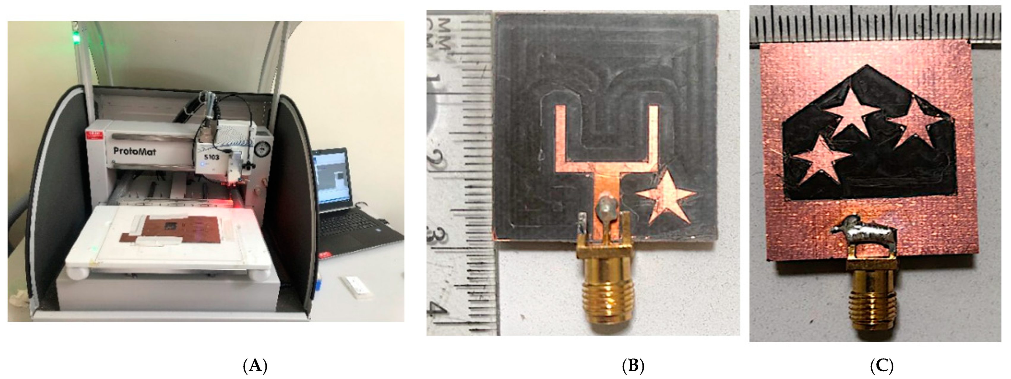
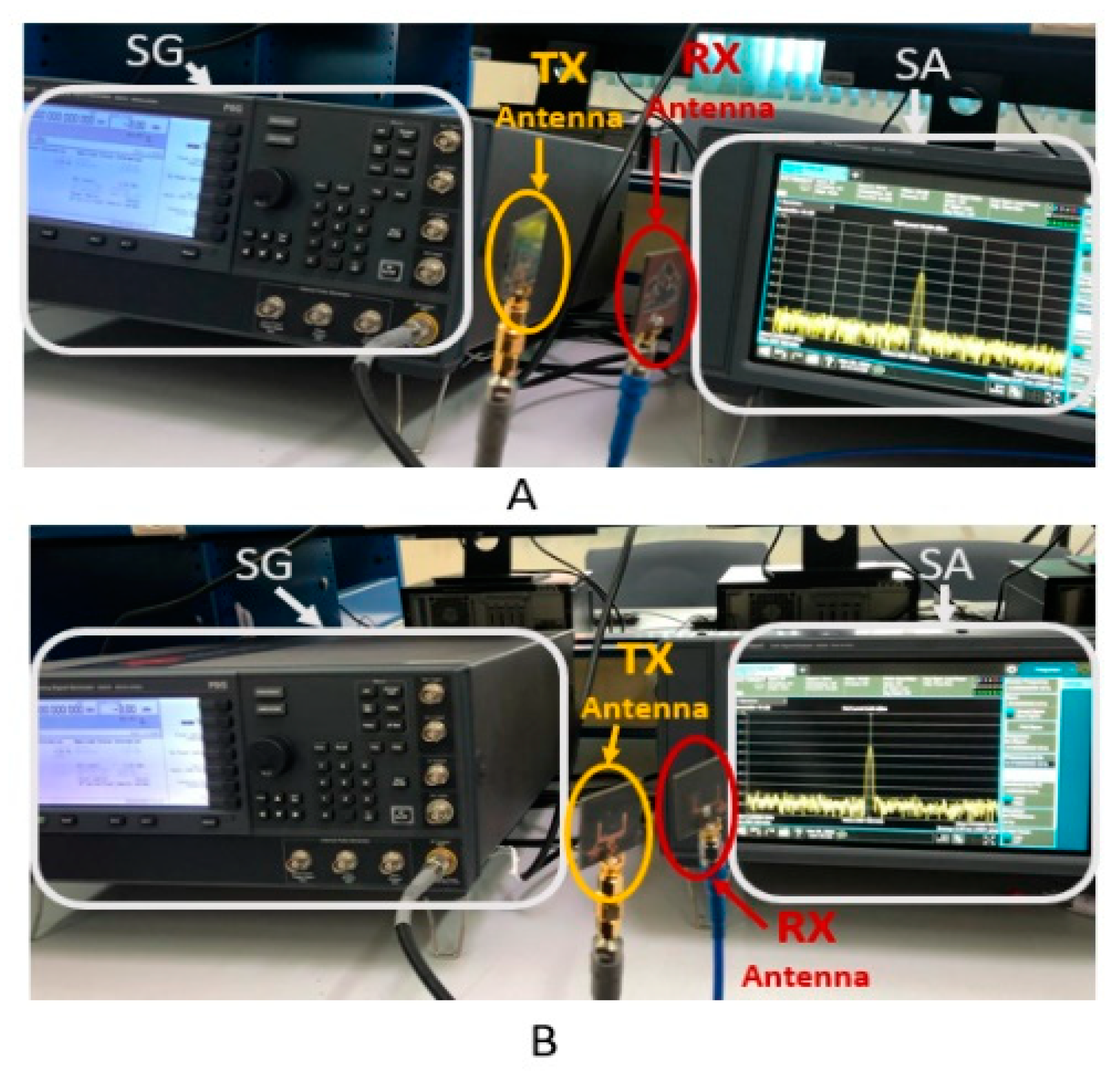
4.3. Microwave Imaging Experimental Setup
5. Conclusions
Author Contributions
Funding
Institutional Review Board Statement
Informed Consent Statement
Data Availability Statement
Conflicts of Interest
References
- Bhargava, D.; Rattanadecho, P. Microwave imaging of breast cancer: Simulation analysis of SAR and temperature in tumors for different age and type. Case Stud. Therm. Eng. 2022, 31, 101843. [Google Scholar] [CrossRef]
- Breast, Globocan, International Agency for Research on Cancer, World Health Organization. 2020. Available online: https://gco.iarc.fr/today/data/factsheets/cancers/39-All-cancers-fact-sheet.pdf (accessed on 27 March 2022).
- Lizzi, F.; Scapicchio, C.; Laruina, F.; Retico, A.; Fantacci, M.E. Convolutional Neural Networks for Breast Density Classification: Performance and Explanation Insights. Appl. Sci. 2021, 12, 148. [Google Scholar] [CrossRef]
- Syed, A.; Sobahi, N.; Sheikh, M.; Mittra, R.; Rmili, H. Modified 16-Quasi Log Periodic Antenna Array for Microwave Imaging of Breast Cancer Detection. Appl. Sci. 2021, 12, 147. [Google Scholar] [CrossRef]
- Janjic, A.; Cayoren, M.; Akduman, I.; Yilmaz, T.; Onemli, E.; Bugdayci, O.; Aribal, M.E. SAFE: A Novel Microwave Imaging System Design for Breast Cancer Screening and Early Detection—Clinical Evaluation. Diagnostics 2021, 11, 533. [Google Scholar] [CrossRef]
- Islam, M.T.; Samsuzzaman; Kibria, S.; Misran, N. Metasurface Loaded High Gain Antenna based Microwave Imaging using Iteratively Corrected Delay Multiply and Sum Algorithm. Sci. Rep. 2019, 9, 17317. [Google Scholar] [CrossRef]
- Song, H.; Sasada, S.; Kadoya, T.; Okada, M.; Arihiro, K.; Xiao, X.; Kikkawa, T. Detectability of Breast Tumor by a Hand-held Impulse-Radar Detector: Performance Evaluation and Pilot Clinical Study. Sci. Rep. 2017, 7, 16353. [Google Scholar] [CrossRef]
- Moloney, B.M.; McAnena, P.F.; Elwahab, S.M.A.; Fasoula, A.; Duchesne, L.; Gil Cano, J.D.; Glynn, C.; O’Connell, A.; Ennis, R.; Lowery, A.J.; et al. Microwave Imaging in Breast Cancer—Results from the First-In-Human Clinical Investigation of the Wavelia System. Acad. Radiol. 2021, 29, S211–S222. [Google Scholar] [CrossRef]
- Pelicano, A.C.; Gonçalves, M.C.T.; Godinho, D.M.; Castela, T.; Orvalho, M.L.; Araújo, N.A.M.; Porter, E.; Conceição, R.C. Development of 3D MRI-Based Anatomically Realistic Models of Breast Tissues and Tumours for Microwave Imaging Diagnosis. Sensors 2021, 21, 8265. [Google Scholar] [CrossRef]
- Wu, L.; Cheng, Z.; Ma, Y.; Li, Y.; Ren, M.; Xing, D.; Qin, H. A Handheld Microwave Thermoacoustic Imaging System With an Impedance Matching Microwave-Sono Probe for Breast Tumor Screening. IEEE Trans. Med Imaging 2021, 41, 1080–1086. [Google Scholar] [CrossRef]
- Martínez-Lozano, A.; Blanco-Angulo, C.; García-Martínez, H.; Gutiérrez-Mazón, R.; Torregrosa-Penalva, G.; Ávila-Navarro, E.; Sabater-Navarro, J. UWB-Printed Rectangular-Based Monopole Antenna for Biological Tissue Analysis. Electronics 2021, 10, 304. [Google Scholar] [CrossRef]
- Zerrad, F.-E.; Taouzari, M.; Makroum, E.M.; Aoufi, J.; Nasraoui, H.; Aksoy, F.G.; Karaaslan, M.; Islam, T. Novel measurement technique to detect breast tumor based on the smallest form factor of UWB patch antenna. Int. J. Microw. Wirel. Technol. 2022, 1–9. [Google Scholar] [CrossRef]
- Mahmud, Z.; Islam, M.T.; Misran, N.; Kibria, S. Samsuzzaman Microwave Imaging for Breast Tumor Detection Using Uniplanar AMC Based CPW-Fed Microstrip Antenna. IEEE Access 2018, 6, 44763–44775. [Google Scholar] [CrossRef]
- Islam, T.; Mahmud, M.Z.; Kibria, S.; Samsuzzaman, M. A Low Cost and Portable Microwave Imaging System for Breast Tumor Detection Using UWB Directional Antenna array. Sci. Rep. 2019, 9, 15491. [Google Scholar] [CrossRef]
- Özmen, H.; Kurt, M.B. Radar-based microwave breast cancer detection system with a high-performance ultrawide band antipodal Vivaldi antenna. Turk. J. Electr. Eng. Comput. Sci. 2021, 29, 2326–2345. [Google Scholar] [CrossRef]
- Zerrad, F.-E.; Taouzari, M.; Makroum, E.M.; El Aoufi, J.; Islam, M.T.; Özkaner, V.; Abdulkarim, Y.I.; Karaaslan, M. Multilayered metamaterials array antenna based on artificial magnetic conductor’s structure for the application diagnostic breast cancer detection with microwave imaging. Med. Eng. Phys. 2021, 99, 103737. [Google Scholar] [CrossRef] [PubMed]
- Banu, S.A.; Jeyanthi, K.M.A. Textile based antenna design for breast cancer detection. Mater. Today Proc. 2022, 62, 4814–4820. [Google Scholar] [CrossRef]
- Zerrad, F.-E.; Taouzari, M.; Makroum, E.M.; Ahmad, S.; Alkurt, F.O.; Karaaslan, M.; Islam, T.; Hussein, M.I. Symmetrical and Asymmetrical Breast Phantoms With 3D-Printed Anatomical Structure for Microwave Imaging of Breast Cancer. IEEE Access 2022, 10, 96896–96908. [Google Scholar] [CrossRef]
- Mahmud, M.Z.; Islam, M.T.; Almutairi, A.F.; Samsuzzaman, M.; Acharjee, U.; Islam, M.T. A Parasitic Resonator-Based Diamond-Shaped Microstrip Antenna for Microwave Imaging Applications. Electronics 2019, 8, 434. [Google Scholar] [CrossRef]
- Tiwari, R.N.; Singh, P.; Kanaujia, B.K. A modified microstrip line fed compact UWB antenna for WiMAX/ISM/WLAN and wireless communications. AEU—Int. J. Electron. Commun. 2019, 104, 58–65. [Google Scholar] [CrossRef]
- Hossain, K.; Sabapathy, T.; Jusoh, M.; Lee, S.-H.; Ab Rahman, K.S.; Kamarudin, M.R. Negative Index Metamaterial-Based Frequency-Reconfigurable Textile CPW Antenna for Microwave Imaging of Breast Cancer. Sensors 2022, 22, 1626. [Google Scholar] [CrossRef]
- O’Loughlin, D.; Elahi, M.; Porter, E.; Shahzad, A.; Oliveira, B.; Glavin, M.; Jones, E.; O’Halloran, M. Open-source Software for Microwave Radar-based Image Reconstruction. In Proceedings of the 12th European Conference on Antennas and Propagation (EuCAP 2018), London, UK , 9–13 April 2018; Volume 2018, p. CP741. [Google Scholar] [CrossRef]
- Kumari, V.; Sheoran, G.; Kanumuri, T. SAR analysis of directive antenna on anatomically real breast phantoms for microwave holography. Microw. Opt. Technol. Lett. 2019, 62, 466–473. [Google Scholar] [CrossRef]
- Moussa, M.N.; Madi, M.A.; Kabalan, K.Y. Breast Tumor Detection, Sizing and Localization Using a 24-Element Antenna Array. IEEE J. Biomed. Health Inform. 2022, 26, 5109–5121. [Google Scholar] [CrossRef] [PubMed]


| Reference | Skin | Fat | Glandular | Tumor | ||||
|---|---|---|---|---|---|---|---|---|
| εr | σ (S/m) | εr | σ (S/m) | εr | σ (S/m) | εr | σ (S/m) | |
| [18] | 38 | 0.94 | 5 | 0.17 | 45 | 1.6 | 56 | 1.7 |
| Material | Quantity | Purpose | ||||
|---|---|---|---|---|---|---|
| Skin | Fat | Gland | Tumor | |||
| Sodium chloride (NaCl) | 5 g | 4 g | 6 g | 8 g | Improve the conductivity | |
| Distilled water | 20 mL | - | 50 mL | 100 mL | Increase the permittivity | |
| Pure petroleum jelly | - | 24 g | - | - | Modify the permittivity | |
| wheat flour | 10 mg | 30 g | 30 g | - | Thickener, Modify the permittivity | |
| Olive oil | - | 30 mL | - | - | Modify the permittivity | |
| Powder dyes | (Orange) | (Yellow) | (Blue) | (Dark Blue) | distinguish the different components | |
| Ref | Antenna | Fidelity Factor (%) | Phantom and Cancer Object | Setup Realization | |||
|---|---|---|---|---|---|---|---|
| Type | Size (mm2) | Operating Frequency Range (GHz) | Gain (dBi) | ||||
| [4] | Quasi Log Periodic | 50 × 40 | 2–5 | 4.6 | Not reported | no | no |
| [23] | Vivaldi antenna | 50 × 25 | 4–16 | 3.53 | Not reported | Lab-made phantom | yes |
| [19] | Microstrip Antenna Composed of Parasitic Resonator | 30 × 25 | 2.7–10.3 | 6.2 | Not reported | no | no |
| [11] | UWB-Printed Rectangular-Based Monopole Antenna | 40 × 36 | 2.7–11.4 | 6.6 | 88–93 | no | no |
| [24] | Slotted Rectangular-patch | 10 × 10 | 7.83–8.17 | 2.43 | Not reported | no | no |
| proposed | Slotted antenna with four-star shape parasitic elements | 29 × 26.6 | 3.8–10.1 | 6.8 | 91.6–91.2 | Lab-made realistic heterogeneous phantom | yes |
Disclaimer/Publisher’s Note: The statements, opinions and data contained in all publications are solely those of the individual author(s) and contributor(s) and not of MDPI and/or the editor(s). MDPI and/or the editor(s) disclaim responsibility for any injury to people or property resulting from any ideas, methods, instructions or products referred to in the content. |
© 2023 by the authors. Licensee MDPI, Basel, Switzerland. This article is an open access article distributed under the terms and conditions of the Creative Commons Attribution (CC BY) license (https://creativecommons.org/licenses/by/4.0/).
Share and Cite
Zerrad, F.-e.; Taouzari, M.; Makroum, E.M.; Aoufi, J.E.; Qanadli, S.D.; Karaaslan, M.; Al-Gburi, A.J.A.; Zakaria, Z. Microwave Imaging Approach for Breast Cancer Detection Using a Tapered Slot Antenna Loaded with Parasitic Components. Materials 2023, 16, 1496. https://doi.org/10.3390/ma16041496
Zerrad F-e, Taouzari M, Makroum EM, Aoufi JE, Qanadli SD, Karaaslan M, Al-Gburi AJA, Zakaria Z. Microwave Imaging Approach for Breast Cancer Detection Using a Tapered Slot Antenna Loaded with Parasitic Components. Materials. 2023; 16(4):1496. https://doi.org/10.3390/ma16041496
Chicago/Turabian StyleZerrad, Fatima-ezzahra, Mohamed Taouzari, El Mostafa Makroum, Jamal El Aoufi, Salah D. Qanadli, Muharrem Karaaslan, Ahmed Jamal Abdullah Al-Gburi, and Zahriladha Zakaria. 2023. "Microwave Imaging Approach for Breast Cancer Detection Using a Tapered Slot Antenna Loaded with Parasitic Components" Materials 16, no. 4: 1496. https://doi.org/10.3390/ma16041496
APA StyleZerrad, F.-e., Taouzari, M., Makroum, E. M., Aoufi, J. E., Qanadli, S. D., Karaaslan, M., Al-Gburi, A. J. A., & Zakaria, Z. (2023). Microwave Imaging Approach for Breast Cancer Detection Using a Tapered Slot Antenna Loaded with Parasitic Components. Materials, 16(4), 1496. https://doi.org/10.3390/ma16041496