
Plasma Electrolytic Oxidation of Titanium in Ni and Cu Hydroxide Suspensions towards Preparation of Electrocatalysts for Urea Oxidation

Abstract
:1. Introduction
2. Materials and Methods
3. Results
4. Conclusions
Author Contributions
Funding
Data Availability Statement
Conflicts of Interest
References
- Wongyao, N.; Therdthianwong, A.; Therdthianwong, S. Performance of Direct Alcohol Fuel Cells Fed with Mixed Methanol/Ethanol Solutions. Energy Convers. Manag. 2011, 52, 2676–2681. [Google Scholar] [CrossRef]
- Gong, L.; Yang, Z.; Li, K.; Xing, W.; Liu, C.; Ge, J. Recent Development of Methanol Electrooxidation Catalysts for Direct Methanol Fuel Cell. J. Energy Chem. 2018, 27, 1618–1628. [Google Scholar] [CrossRef]
- Mao, Y.H.; Chen, C.Y.; Fu, J.X.; Lai, T.Y.; Lu, F.H.; Tsai, Y.C. Electrodeposition of Nickel-copper on Titanium Nitride for Methanol Electrooxidation. Surf. Coat. Technol. 2018, 350, 949–953. [Google Scholar] [CrossRef]
- Leo, T.J.; Raso, M.A.; Navarro, E.; Sánchez-De-La-Blanca, E. Comparative Exergy Analysis of Direct Alcohol Fuel Cells Using Fuel Mixtures. J. Power Sources 2011, 196, 1178–1183. [Google Scholar] [CrossRef] [Green Version]
- Kamarudin, M.Z.F.; Kamarudin, S.K.; Masdar, M.S.; Daud, W.R.W. Review: Direct Ethanol Fuel Cells. Int. J. Hydrog. Energy 2013, 38, 9438–9453. [Google Scholar] [CrossRef]
- Bonastre, A.M. Catalysts for Alcohol-Fuelled Direct Oxidation Fuel Cells. Platin. Met. Rev. 2013, 57, 297–301. [Google Scholar] [CrossRef]
- Xu, W.; Wu, Z.; Tao, S. Urea-Based Fuel Cells and Electrocatalysts for Urea Oxidation. Energy Technol. 2016, 4, 1329–1337. [Google Scholar] [CrossRef] [Green Version]
- Sayed, E.T.; Eisa, T.; Mohamed, H.O.; Abdelkareem, M.A.; Allagui, A.; Alawadhi, H.; Chae, K.J. Direct Urea Fuel Cells: Challenges and Opportunities. J. Power Sources 2019, 417, 159–175. [Google Scholar] [CrossRef]
- Josef, H.F.; Harro, P. Urea. In Ullmann’s Encyclopedia of Industrial Chemistry; Wiley-VCH: Weinheim, Germany, 2005. [Google Scholar]
- Urbańczyk, E.; Sowa, M.; Simka, W. Urea Removal from Aqueous Solutions—A Review. J. Appl. Electrochem. 2016, 46, 1011–1029. [Google Scholar] [CrossRef] [Green Version]
- Singh, R.K.; Rajavelu, K.; Montag, M.; Schechter, A. Advances in Catalytic Electrooxidation of Urea: A Review. Energy Technol. 2021, 9, 2100017. [Google Scholar] [CrossRef]
- Li, J.; Wang, S.; Sun, S.; Wu, X.; Zhang, B.; Feng, L. A Review of Hetero-Structured Ni-Based Active Catalysts for Urea Electrolysis. J. Mater. Chem. A 2022, 10, 9308–9326. [Google Scholar] [CrossRef]
- Goda, M.A.; Abd El-Moghny, M.G.; El-Deab, M.S. Enhanced Electrocatalytic Oxidation of Urea at CuOx-NiOx Nanoparticle-Based Binary Catalyst Modified Polyaniline/GC Electrodes. J. Electrochem. Soc. 2020, 167, 064522. [Google Scholar] [CrossRef]
- Shi, W.; Lian, J. Mesoporous Cu(OH)2 Nanowire Arrays for Urea Electrooxidation in Alkaline Medium. Mater. Chem. Phys. 2020, 242, 122517. [Google Scholar] [CrossRef]
- Lukiyanchuk, I.V.; Rudnev, V.S.; Tyrina, L.M. Plasma Electrolytic Oxide Layers as Promising Systems for Catalysis. Surf. Coat. Technol. 2016, 307, 1183–1193. [Google Scholar] [CrossRef]
- Sikdar, S.; Menezes, P.V.; Maccione, R.; Jacob, T.; Menezes, P.L. Plasma Electrolytic Oxidation (Peo) Process—Processing, Properties, and Applications. Nanomaterials 2021, 11, 61375. [Google Scholar] [CrossRef]
- Mortazavi, G.; Jiang, J.; Meletis, E.I. Investigation of the Plasma Electrolytic Oxidation Mechanism of Titanium. Appl. Surf. Sci. 2019, 488, 370–382. [Google Scholar] [CrossRef]
- Yu, X.; Yan, Z.; Qin, H.; Wu, M.; Wang, A.; Chen, L. In-Situ Growth of Nanostructured Catalytic Coatings via One-Step Plasma Electrolytic Oxidation. Appl. Surf. Sci. 2019, 479, 738–744. [Google Scholar] [CrossRef]
- Aliofkhazraei, M.; Macdonald, D.D.; Matykina, E.; Parfenov, E.V.; Egorkin, V.S.; Curran, J.A.; Troughton, S.C.; Sinebryukhov, S.L.; Gnedenkov, S.V.; Lampke, T.; et al. Review of Plasma Electrolytic Oxidation of Titanium Substrates: Mechanism, Properties, Applications and Limitations. Appl. Surf. Sci. Adv. 2021, 5, 100121. [Google Scholar] [CrossRef]
- Han, J.X.; Cheng, Y.L.; Tu, W.B.; Zhan, T.Y.; Cheng, Y.L. The Black and White Coatings on Ti-6Al-4V Alloy or Pure Titanium by Plasma Electrolytic Oxidation in Concentrated Silicate Electrolyte. Appl. Surf. Sci. 2018, 428, 684–697. [Google Scholar] [CrossRef]
- Collivignarelli, M.C.; Abbà, A.; Carnevale Miino, M.; Arab, H.; Bestetti, M.; Franz, S. Decolorization and Biodegradability of a Real Pharmaceutical Wastewater Treated by H2O2-Assisted Photoelectrocatalysis on TiO2 Meshes; Elsevier: Amsterdam, The Netherlands, 2020; Volume 387, ISBN 0000000213. [Google Scholar]
- Friedemann, A.E.R.; Thiel, K.; Gesing, T.M.; Plagemann, P. Photocatalytic Activity of TiO2 Layers Produced with Plasma Electrolytic Oxidation. Surf. Coat. Technol. 2018, 344, 710–721. [Google Scholar] [CrossRef]
- Franz, S.; Perego, D.; Marchese, O.; Lucotti, A.; Bestetti, M. Photoactive TiO2 Coatings Obtained by Plasma Electrolytic Oxidation in Refrigerated Electrolytes. Appl. Surf. Sci. 2016, 385, 498–505. [Google Scholar] [CrossRef]
- Franz, S.; Arab, H.; Lucotti, A.; Castiglioni, C.; Vicenzo, A.; Morini, F.; Bestetti, M. Exploiting Direct Current Plasma Electrolytic Oxidation to Boost Photoelectrocatalysis. Catalysts 2020, 10, 30325. [Google Scholar] [CrossRef] [Green Version]
- Collivignarelli, M.C.; Miino, M.C.; Arab, H.; Bestetti, M.; Franz, S. Wastewater Treatment Plants Effluents: Photoelectrocatalysis vs. Photocatalysis and photolysis. Water 2021, 13, 821. [Google Scholar] [CrossRef]
- Yao, Z.; Hu, B.; Shen, Q.; Niu, A.; Jiang, Z.; Su, P.; Ju, P. Preparation of Black High Absorbance and High Emissivity Thermal Control Coating on Ti Alloy by Plasma Electrolytic Oxidation. Surf. Coat. Technol. 2014, 253, 166–170. [Google Scholar] [CrossRef]
- Tyrina, L.M.; Rudnev, V.S.; Lukiyanchuk, I.V.; Ustinov, A.Y.; Sergienko, V.I.; Vasil’eva, M.S.; Kondrikov, N.B. Ni- and Cu-Containing Oxide Layers on Aluminum: Formation, Composition, and Catalytic Properties. Dokl. Phys. Chem. 2007, 415, 183–185. [Google Scholar] [CrossRef]
- Lukiyanchuk, I.V.; Tyrina, L.M.; Rudnev, V.S.; Ustinov, A.Y.; Nedozorov, P.M.; Vasil’eva, M.S. Catalytic Properties of Aluminum/Nickel-, Copper-Containing Oxide Film Compositions. Kinet. Catal. 2008, 49, 439–445. [Google Scholar] [CrossRef]
- Rudnev, V.S.; Tyrina, L.M.; Ustinov, A.Y.; Vybornova, S.; Lukiyanchuk, I.V. Comparative Analysis of the Composition, Structure, and Catalytic Activity of the NiO-CuO-TiO2 on Titanium and NiO-CuO-Al2O3 on Aluminum Composites. Kinet. Catal. 2010, 51, 266–272. [Google Scholar] [CrossRef]
- Yao, Z.; Jia, F.; Tian, S.; Li, C.; Jiang, Z.; Bai, X. Microporous Ni-Doped TiO2 Film Photocatalyst by Plasma Electrolytic Oxidation. ACS Appl. Mater. Interfaces 2010, 2, 2617–2622. [Google Scholar] [CrossRef]
- Kim, Y.S.; Shin, K.R.; Kim, G.W.; Ko, Y.G.; Shin, D.H. Photocatalytic Activity of TiO2 Film Containing Fe2O3 via Plasma Electrolytic Oxidation. Surf. Eng. 2016, 32, 443–447. [Google Scholar] [CrossRef]
- Rokosz, K.; Hryniewicz, T.; Raaen, S.; Gaiaschi, S.; Chapon, P.; Matỳsek, D.; Pietrzak, K.; Szymańska, M.; Dudek, Ł. Metal Ions Supported Porous Coatings by Using AC Plasma Electrolytic Oxidation Processing. Materials 2020, 13, 3838. [Google Scholar] [CrossRef]
- Rokosz, K.; Hryniewicz, T.; Kacalak, W.; Tandecka, K.; Raaen, S.; Gaiaschi, S.; Chapon, P.; Malorny, W.; Matýsek, D.; Pietrzak, K.; et al. Phosphate Coatings Enriched with Copper on Titanium Substrate Fabricated via DC-PEO Process. Materials 2020, 13, 1295. [Google Scholar] [CrossRef] [Green Version]
- Lukiyanchuk, I.V.; Vasilyeva, M.S.; Ustinov, A.Y.; Bryzhin, A.A.; Tarkhanova, I.G. Ti/TiO2/NiWO4 + WO3 Composites for Oxidative Desulfurization and Denitrogenation. Surf. Coat. Technol. 2022, 434, 128200. [Google Scholar] [CrossRef]
- Jiang, Y.; Liu, B.; Yang, L.; Yang, B.; Liu, X.; Liu, L.; Weimer, C.; Jiang, X. Size-Controllable Ni5TiO7 nanowires as Promising Catalysts for CO Oxidation. Sci. Rep. 2015, 5, 1–10. [Google Scholar] [CrossRef] [Green Version]
- Rudnev, V.S.; Wybornov, S.; Lukiyanchuk, I.V.; Staedler, T.; Jiang, X.; Ustinov, A.Y.; Vasilyeva, M.S. Thermal Behavior of Ni- and Cu-Containing Plasma Electrolytic Oxide Coatings on Titanium. Appl. Surf. Sci. 2012, 258, 8667–8672. [Google Scholar] [CrossRef]
- Jiang, X.; Zhang, L.; Wybornov, S.; Staedler, T.; Hein, D.; Wiedenmann, F.; Krumm, W.; Rudnev, V.; Lukiyanchuk, I. Highly Efficient Nanoarchitectured Ni5TiO7 Catalyst for Biomass Gasification. ACS Appl. Mater. Interfaces 2012, 4, 4062–4066. [Google Scholar] [CrossRef] [PubMed]
- Lukiyanchuk, I.V.; Chernykh, I.V.; Rudnev, V.S.; Ustinov, A.Y.; Tyrina, L.M.; Nedozorov, P.M.; Dmitrieva, E.E. Catalytically Active Cobalt-Copper-Oxide Layers on Aluminum and Titanium. Prot. Met. Phys. Chem. Surf. 2014, 50, 209–217. [Google Scholar] [CrossRef]
- Vasil’eva, M.S.; Rudnev, V.S.; Sklyarenko, O.E.; Tyrina, L.M.; Kondrikov, N.B. Titanium-Supported Nickel-Copper Oxide Catalysts for Oxidation of Carbon(II) Oxide. Russ. J. Gen. Chem. 2010, 80, 1557–1562. [Google Scholar] [CrossRef]
- Lukiyanchuk, I.V.; Chernykh, I.V.; Rudnev, V.S.; Tyrina, L.M.; Ustinov, A.Y. Silicate Coatings on Titanium Modified by Cobalt and/or Copper Oxides and Their Activity in CO Oxidation. Prot. Met. Phys. Chem. Surf. 2015, 51, 448–457. [Google Scholar] [CrossRef]
- Vasilyeva, M.S.; Rudnev, V.S.; Zvereva, A.A.; Ustinov, A.Y.; Arefieva, O.D.; Kuryavyi, V.G.; Zverev, G.A. FeOx, SiO2, TiO2/Ti Composites Prepared Using Plasma Electrolytic Oxidation as Photo-Fenton-like Catalysts for Phenol Degradation. J. Photochem. Photobiol. A Chem. 2018, 356, 38–45. [Google Scholar] [CrossRef]
- Marinina, G.I.; Vasilyeva, M.S.; Lapina, A.S.; Ustinov, A.Y.; Rudnev, V.S. Electroanalytical Properties of Metal-Oxide Electrodes Formed by Plasma Electrolytic Oxidation. J. Electroanal. Chem. 2013, 689, 262–268. [Google Scholar] [CrossRef]
- Sun, B.; Zhou, G.; Gao, T.; Zhang, H.; Yu, H. NiO Nanosheet/TiO2 Nanorod-Constructed p-n Heterostructures for Improved Photocatalytic Activity. Appl. Surf. Sci. 2016, 364, 322–331. [Google Scholar] [CrossRef]
- Chen, W.; Wang, Y.; Liu, S.; Gao, L.; Mao, L.; Fan, Z.; Shangguan, W.; Jiang, Z. Non-Noble Metal Cu as a Cocatalyst on TiO2 Nanorod for Highly Efficient Photocatalytic Hydrogen Production. Appl. Surf. Sci. 2018, 445, 527–534. [Google Scholar] [CrossRef] [Green Version]
- Deng, X.; Zhang, H.; Ma, Q.; Cui, Y.; Cheng, X.; Li, X.; Xie, M.; Cheng, Q. Fabrication of P-NiO/n-TiO2 Nano-Tube Arrays Photoelectrode and Its Enhanced Photocatalytic Performance for Degradation of 4-Chlorphenol. Sep. Purif. Technol. 2017, 186, 1–9. [Google Scholar] [CrossRef]
- Díaz-Real, J.A.; Ortiz-Ortega, E.; Gurrola, M.P.; Ledesma-Garcia, J.; Arriaga, L.G. Light-Harvesting Ni/TiO2 Nanotubes as Photo-Electrocatalyst for Alcohol Oxidation in Alkaline Media. Electrochim. Acta 2016, 206, 388–399. [Google Scholar] [CrossRef]
- Ahmed, M.A. Synthesis and Structural Features of Mesoporous NiO/TiO2 Nanocomposites Prepared by Sol-Gel Method for Photodegradation of Methylene Blue Dye. J. Photochem. Photobiol. A Chem. 2012, 238, 63–70. [Google Scholar] [CrossRef]
- Cao, H.; Fan, Z.; Hou, G.; Tang, Y.; Zheng, G. Ball-Flower-Shaped Ni Nanoparticles on Cu Modified TiO2 Nanotube Arrays for Electrocatalytic Oxidation of Methanol. Electrochim. Acta 2014, 125, 275–281. [Google Scholar] [CrossRef]
- Ahmed, S.A. Ferromagnetism in Cr-, Fe-, and Ni-Doped TiO2 Samples. J. Magn. Magn. Mater. 2017, 442, 152–157. [Google Scholar] [CrossRef]
- Sun, T.; Fan, J.; Liu, E.; Liu, L.; Wang, Y.; Dai, H.; Yang, Y.; Hou, W.; Hu, X.; Jiang, Z. Fe and Ni Co-Doped TiO2 Nanoparticles Prepared by Alcohol-Thermal Method: Application in Hydrogen Evolution by Water Splitting under Visible Light Irradiation. Powder Technol. 2012, 228, 210–218. [Google Scholar] [CrossRef]
- Macovei, D.; Tiron, V.; Adomnitei, C.; Luca, D.; Dobromir, M.; Antohe, S.; Mardare, D. On the Hydrophilicity of Ni-Doped TiO2 Thin Films. A Study by X-Ray Absorption Spectroscopy. Thin Solid Film. 2018, 657, 42–49. [Google Scholar] [CrossRef]
- Wang, G.; Ling, Y.; Lu, X.; Wang, H.; Qian, F.; Tong, Y.; Li, Y. Solar Driven Hydrogen Releasing from Urea and Human Urine. Energy Environ. Sci. 2012, 5, 8215–8219. [Google Scholar] [CrossRef]
- Alami, A.H.; Abdelkareem, M.A.; Faraj, M.; Aokal, K.; Al Safarini, N. Titanium Dioxide-Coated Nickel Foam Photoelectrodes for Direct Urea Fuel Cell Applications. Energy 2020, 208, 118253. [Google Scholar] [CrossRef]
- Sakhnenko, N.D.; Ved, M.V.; Karakurkchi, A.V. Effect of Doping Metals on the Structure of PEO Coatings on Titanium. Int. J. Chem. Eng. 2018, 2018, 4608485. [Google Scholar] [CrossRef]
- Malyshev, V.N.; Zorin, K.M. Features of Microarc Oxidation Coatings Formation Technology in Slurry Electrolytes. Appl. Surf. Sci. 2007, 254, 1511–1516. [Google Scholar] [CrossRef]
- Soejima, T.; Yagyu, H.; Ito, S. One-Pot Synthesis and Photocatalytic Activity of Fe-Doped TiO2 Films with Anatase-Rutile Nanojunction Prepared by Plasma Electrolytic Oxidation. J. Mater. Sci. 2011, 46, 5378–5384. [Google Scholar] [CrossRef]
- Lu, X.; Mohedano, M.; Blawert, C.; Matykina, E.; Arrabal, R.; Kainer, K.U.; Zheludkevich, M.L. Plasma Electrolytic Oxidation Coatings with Particle Additions—A Review. Surf. Coat. Technol. 2016, 307, 1165–1182. [Google Scholar] [CrossRef]
- Kim, T.W.; Ha, H.W.; Paek, M.J.; Hyun, S.H.; Choy, J.H.; Hwang, S.J. Unique Phase Transformation Behavior and Visible Light Photocatalytic Activity of Titanium Oxide Hybridized with Copper Oxide. J. Mater. Chem. 2010, 20, 3238–3245. [Google Scholar] [CrossRef]
- Chen, C.J.; Liao, C.H.; Hsu, K.C.; Wu, Y.T.; Wu, J.C.S. P-N Junction Mechanism on Improved NiO/TiO2 Photocatalyst. Catal. Commun. 2011, 12, 1307–1310. [Google Scholar] [CrossRef]
- Yao, R.; Li, Y.; Yao, Z.; Zhang, P.; Lu, S.; Wu, X. Black PEO Coating with Enhanced Thermal Stability on Titanium Alloy and Its Thermal Control Properties. Surf. Coat. Technol. 2022, 429, 127934. [Google Scholar] [CrossRef]
- Khokhryakov, Y.V.; Butyagin, P.I.; Mamaev, A.I. Formation of Dispersed Particles during Plasma Oxidation. J. Mater. Sci. 2005, 40, 3007–3008. [Google Scholar] [CrossRef]
- Arab, H.; Chiarello, G.L.; Selli, E.; Bomboi, G.; Calloni, A.; Bussetti, G.; Albani, G.; Bestetti, M.; Franz, S. Ni-Doped Titanium Dioxide Films Obtained by Plasma Electrolytic Oxidation in Refrigerated Electrolytes. Surfaces 2020, 3, 168–181. [Google Scholar] [CrossRef] [Green Version]
- Coto, M.; Troughton, S.C.; Knight, P.; Joshi, R.; Francis, R.; Kumar, R.V.; Clyne, T.W. Optimization of the Microstructure of TiO2 Photocatalytic Surfaces Created by Plasma Electrolytic Oxidation of Titanium Substrates. Surf. Coat. Technol. 2021, 411, 127000. [Google Scholar] [CrossRef]
- Vedharathinam, V.; Botte, G.G. Understanding the Electro-Catalytic Oxidation Mechanism of Urea on Nickel Electrodes in Alkaline Medium. Electrochim. Acta 2012, 81, 292–300. [Google Scholar] [CrossRef]
- Bezboruah, J.; Sanke, D.M.; Munde, A.V.; Das, S.; Karmakar, H.S.; Zade, S.S. Nickel-Doped TiO2 and Thiophene-Naphthalenediimide Copolymer Based Inorganic/Organic Nano-Heterostructure for the Enhanced Photoelectrochemical Urea Oxidation Reaction. Int. J. Hydrog. Energy 2022, 48, 7361–7373. [Google Scholar] [CrossRef]
- Tao, Y.; Ma, Z.; Wang, W.; Zhang, C.; Fu, L.; Zhu, Q.; Li, Y.; Li, G.; Zhang, D. Nickel Phosphide Clusters Sensitized TiO2 Nanotube Arrays as Highly Efficient Photoanode for Photoelectrocatalytic Urea Oxidation. Adv. Funct. Mater. 2023, 33, 2211169. [Google Scholar] [CrossRef]


| Sample | KOH, M | Na2SiO3, M | Ni(OH)2, M | Cu(OH)2, M | Voltage, V |
|---|---|---|---|---|---|
| Ref | 0.05 | 0.5 | - | - | 200 |
| Ni I | 0.05 | - | |||
| Ni II | 0.1 | - | |||
| Cu I | - | 0.05 | |||
| Cu II | - | 0.1 | 180 |
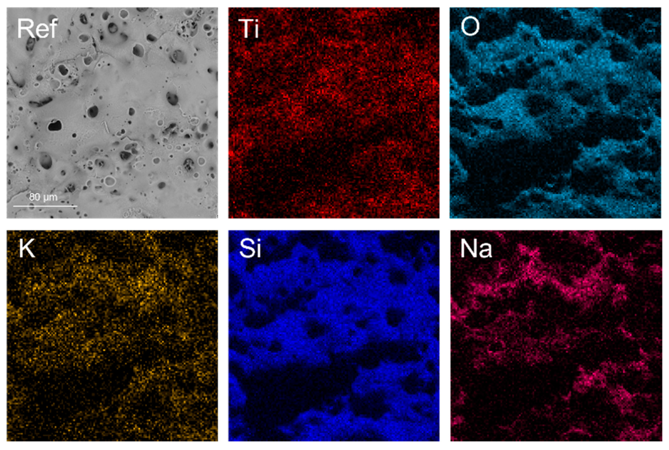
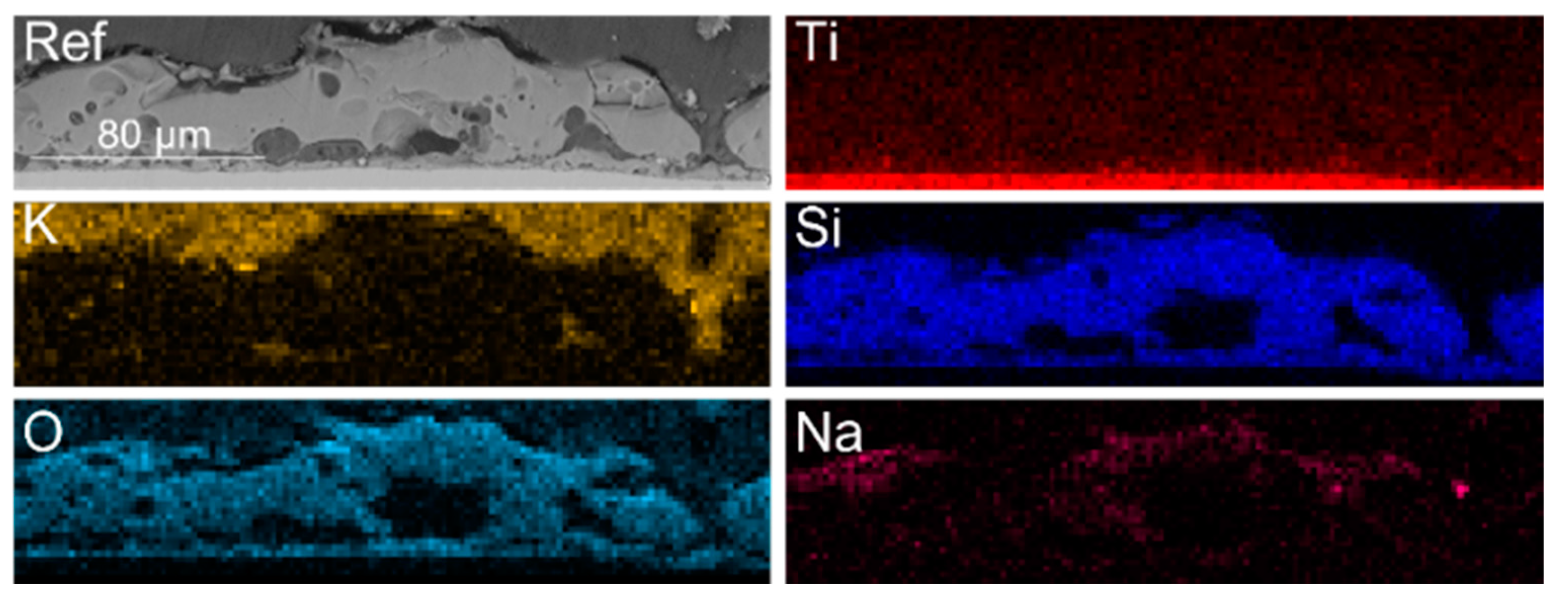
| Sample | Ti | O * | Si | Na | K | Cu | Ni | |
|---|---|---|---|---|---|---|---|---|
| Ref | Surface | 2.1 | 70.6 | 21.1 | 5.7 | 0.6 | - | - |
| Cross section | 9.1 | 77.7 | 11.7 | 1.4 | - | - | - | |
| Ni I | Surface | 1.4 | 70.4 | 21.0 | 6.4 | 0.5 | - | 0.3 |
| Cross section | 9.6 | 76.5 | 13.0 | 0.9 | - | - | 0.1 | |
| Ni II | Surface | 1.7 | 70.5 | 20.0 | 6.9 | 0.6 | - | 0.3 |
| Cross section | 10.13 | 77.3 | 11.6 | 0.8 | - | - | 0.1 | |
| Cu I | Surface | 1.6 | 70.8 | 20.8 | 6.2 | 0.6 | - | - |
| Cross section | 9.2 | 77.9 | 12.5 | 0.5 | - | + | - | |
| Cu II | Surface | 2.1 | 70.8 | 19.8 | 6.8 | 0.6 | + | - |
| Cross section | 9.2 | 78.1 | 11.9 | 0.6 | - | 0.1 | - |
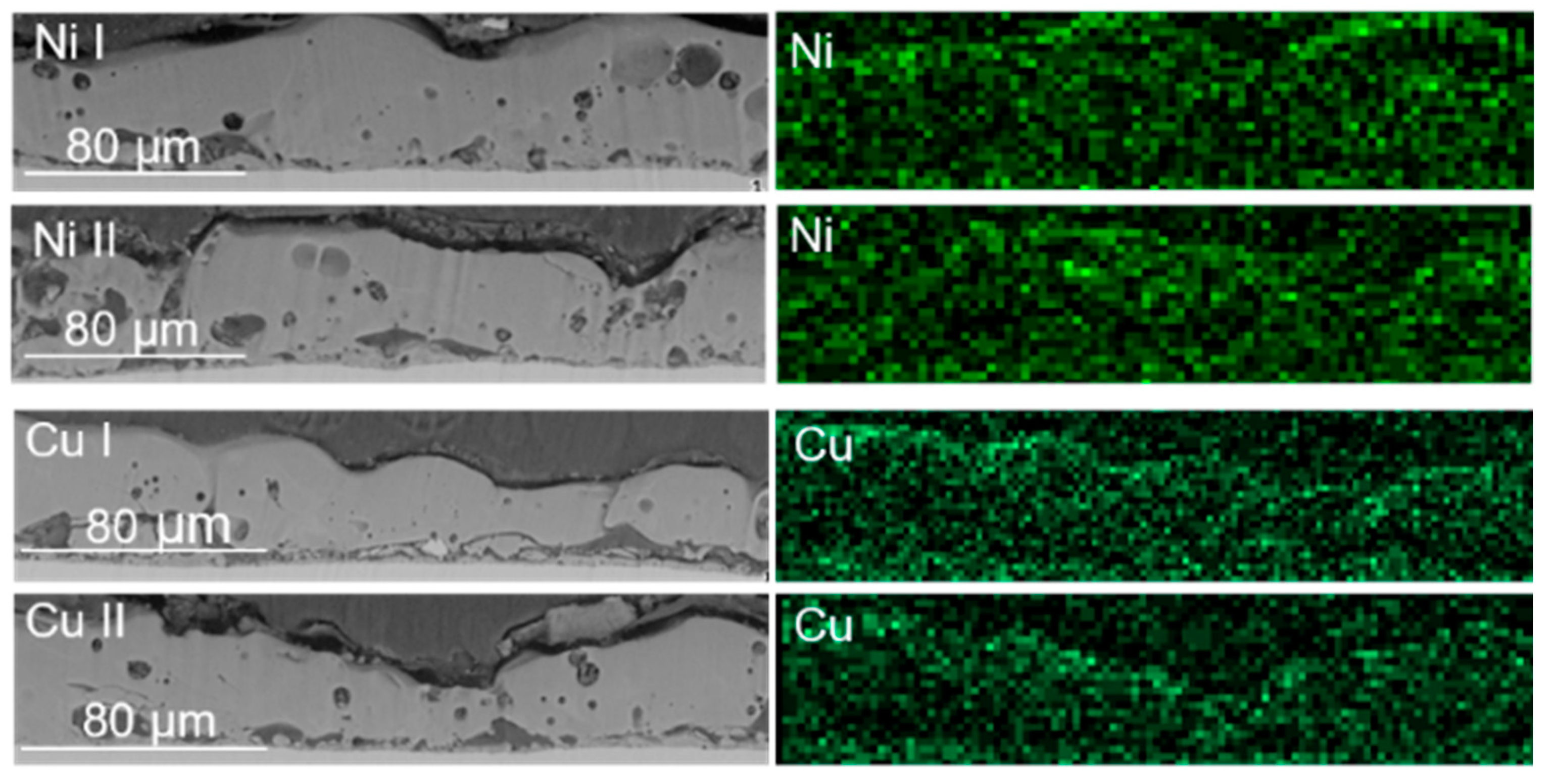
| Sample | PEO Bath | Form of Metal Additive | Metal Concentration, M | Metal Presence in the Layer, at% (EDS Data) | Reference |
|---|---|---|---|---|---|
| Cu I | Alkaline | Hydroxide suspension | 0.05 | 0 | This paper |
| Cu II | 0.10 | 0 | |||
| Ni I | 0.05 | 0.3 | |||
| Ni II | 0.10 | 0.3 | |||
| Cu | Alkaline | Oxide | 0.04 | 3.22 (wt%) | [18] |
| Ni | Neutral | Acetate | 0.06 | 1.25 | [26] |
| Ni | Neutral | Acetate | 0.08 | 4.8 (XRD) 5.5 (XES) | [27,28,29] |
| Cu | 0.025 | 0.4 (XRD) 5.9 (XES) | |||
| Cu | Acidic | Nitrite | 1.04 | 0.41 | [32] |
| Cu | Acidic | Nitrite | 2.70 | 2.59 | [33] |
| Ni | Acidic | Acetate | 0.05 | 4.3 | [34] |
| Ni | Alkaline | Acetate | 0.03 | 1.07 | [30] |
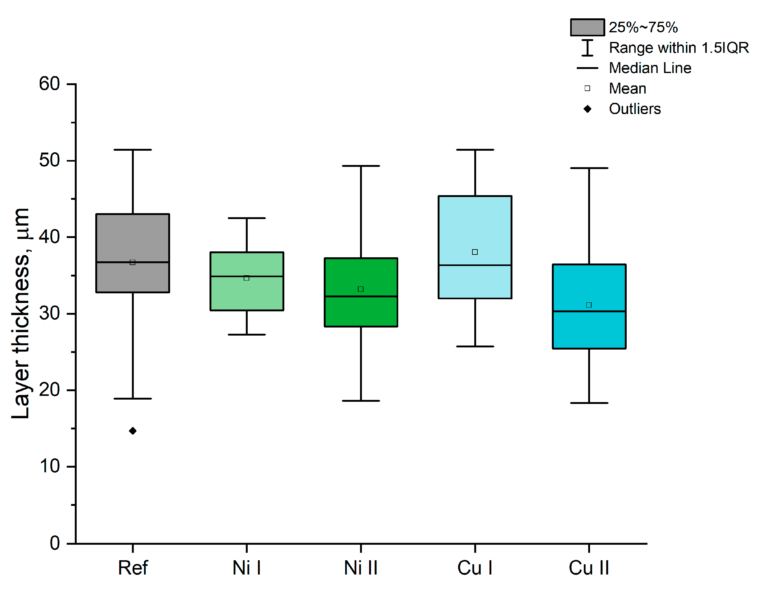
| Sample | Average Ra, μm | Average Rz, μm |
|---|---|---|
| Ref | 5.43 ± 1.33 | 31.67 ± 6.53 |
| Ni I | 6.03 ± 0.75 | 33.89 ± 3.87 |
| Ni II | 6.25 ± 0.99 | 34.51 ± 3.35 |
| Cu I | 6.34 ± 0.77 | 34.37 ± 1.21 |
| Cu II | 5.52 ± 0.12 | 30.58 ± 2.56 |
| Sample | i@1 V, μA cm−2 in 1 M KOH | i@1 V, μA cm−2 in 1 M KOH + 0.15 M Urea | E@50 uA cm−2, V in 1 M KOH | E@50 μA cm−2, V in 1 M KOH + 0.15 M Urea |
|---|---|---|---|---|
| Ref | 5 | 2 | - | - |
| Ni I | 99 | 102 | 0.793 | 0.752 |
| Ni II | 79 | 123 | 0.850 | 0.742 |
| Cu I | 71 | 130 | 0.925 | 0.781 |
| Cu II | 15 | 22 | - | - |
Disclaimer/Publisher’s Note: The statements, opinions and data contained in all publications are solely those of the individual author(s) and contributor(s) and not of MDPI and/or the editor(s). MDPI and/or the editor(s) disclaim responsibility for any injury to people or property resulting from any ideas, methods, instructions or products referred to in the content. |
© 2023 by the authors. Licensee MDPI, Basel, Switzerland. This article is an open access article distributed under the terms and conditions of the Creative Commons Attribution (CC BY) license (https://creativecommons.org/licenses/by/4.0/).
Share and Cite
Wala, M.; Łubiarz, D.; Waloszczyk, N.; Simka, W. Plasma Electrolytic Oxidation of Titanium in Ni and Cu Hydroxide Suspensions towards Preparation of Electrocatalysts for Urea Oxidation. Materials 2023, 16, 2191. https://doi.org/10.3390/ma16062191
Wala M, Łubiarz D, Waloszczyk N, Simka W. Plasma Electrolytic Oxidation of Titanium in Ni and Cu Hydroxide Suspensions towards Preparation of Electrocatalysts for Urea Oxidation. Materials. 2023; 16(6):2191. https://doi.org/10.3390/ma16062191
Chicago/Turabian StyleWala, Marta, Dorota Łubiarz, Natalia Waloszczyk, and Wojciech Simka. 2023. "Plasma Electrolytic Oxidation of Titanium in Ni and Cu Hydroxide Suspensions towards Preparation of Electrocatalysts for Urea Oxidation" Materials 16, no. 6: 2191. https://doi.org/10.3390/ma16062191