
Barbed Dental Ti6Al4V Alloy Screw: Design and Bench Testing
 , and
, and
Abstract
:
1. Introduction
2. Material and Methods
Implant Testing
3. Statistical Analysis
4. Results
5. Discussion
6. Strengths and Limitations
7. Conclusions
Author Contributions
Funding
Conflicts of Interest
References
- de Oliveira, C.; Sabbah, W.; Schneider, I.J.C.; Bernabé, E. Complete Tooth Loss and Allostatic Load Changes Later in Life: A 12-Year Follow-Up Analysis of the English Longitudinal Study of Ageing. Psychosom. Med. 2021, 83, 247–255. [Google Scholar] [CrossRef] [PubMed]
- Pye, S.R.; Ward, K.A.; Cook, M.J.; Laurent, M.R.; Gielen, E.; Borghs, H.; Adams, J.E.; Boonen, S.; Vanderschueren, D.; Wu, F.C.; et al. Bone turnover predicts change in volumetric bone density and bone geometry at the radius in men. Osteoporos. Int. 2017, 28, 935–944. [Google Scholar] [CrossRef] [PubMed] [Green Version]
- Willers, C.; Norton, N.; Harvey, N.C.; Jacobson, T.; Johansson, H.; Lorentzon, M.; McCloskey, E.V.; Borgström, F.; Kanis, J.A.; SCOPE review panel of the IOF. Osteoporosis in Europe: A compendium of country-specific reports. Arch. Osteoporos. 2022, 17, 23. [Google Scholar] [CrossRef]
- Esposito, M.; Grusovin, M.G.; Maghaireh, H.; Worthington, H.V. Interventions for replacing missing teeth: Different times for loading dental implants. Cochrane Database Syst. Rev. 2013, 2013, CD003878. [Google Scholar] [CrossRef] [PubMed] [Green Version]
- Chackartchi, T.; Romanos, G.E.; Sculean, A. Soft tissue-related complications and management around dental implants. Periodontology 2019, 81, 124–138. [Google Scholar] [CrossRef]
- Almutairi, A.S.; Walid, M.A.; Alkhodary, M.A. The effect of osseodensification and different thread designs on the dental implant primary stability. F1000Research 2018, 7, 1898. [Google Scholar] [CrossRef] [Green Version]
- Bencharit, S.; Byrd, W.C.; Altarawneh, S.; Hosseini, B.; Leong, A.; Reside, G.; Morelli, T.; Offenbacher, S. Development and Applications of Porous Tantalum Trabecular Metal Enhanced Titanium Dental Implants. Clin. Implant. Dent. Relat. Res. 2014, 16, 817–826. [Google Scholar] [CrossRef] [Green Version]
- Haugen, H.J.; Chen, H. Is There a Better Biomaterial for Dental Implants than Titanium?—A Review and Meta-Study Analysis. J. Funct. Biomater. 2022, 13, 46. [Google Scholar] [CrossRef]
- Chen, H.; Liu, N.; Xu, X.; Qu, X.; Lu, E. Smoking, Radiotherapy, Diabetes and Osteoporosis as Risk Factors for Dental Implant Failure: A Meta-Analysis. PLoS ONE 2013, 8, e71955. [Google Scholar] [CrossRef] [Green Version]
- Ko, S.Y.; Hong, J.Y.; Lee, W.; Chang, Y.Y.; Park, K.B.; Yun, J.H. Osteoconductivity of Porous Titanium Structure on Implants in Osteoporosis. J. Dent. Res. 2021, 100, 1178–1185. [Google Scholar] [CrossRef]
- Schünemann, F.H.; Galárraga-Vinueza, M.E.; Magini, R.; Fredel, M.; Silva, F.; Souza, J.C.; Zhang, Y.; Henriques, B. Zirconia surface modifications for implant dentistry. Mater. Sci. Eng. C Mater. Biol. Appl. 2019, 98, 1294–1305. [Google Scholar] [CrossRef] [PubMed]
- Brånemark, P.I. Osseointegration and its experimental background. J. Prosthet. Dent. 1983, 50, 399–410. [Google Scholar] [CrossRef] [PubMed]
- Bowers, K.T.; Keller, J.C.; Randolph, B.A.; Wick, D.G.; Michaels, C.M. Optimization of surface micromorphology for enhanced osteoblast responses in vitro. Int. J. Oral. Maxillofac. Implant. 1992, 7, 302–310. [Google Scholar]
- Kim, W.J.; Cho, Y.D.; Ku, Y.; Ryoo, H.M. The worldwide patent landscape of dental implant technology. Biomater. Res. 2022, 26, 59. [Google Scholar] [CrossRef] [PubMed]
- Hoque, E.; Showva, N.-N.; Ahmed, M.; Bin Rashid, A.; Sadique, S.E.; El-Bialy, T.; Xu, H. Titanium and titanium alloys in dentistry: Current trends, recent developments, and future prospects. Heliyon 2022, 8, e11300. [Google Scholar] [CrossRef]
- Smeets, R.; Stadlinger, B.; Schwarz, F.; Beck-Broichsitter, B.; Jung, O.; Precht, C.; Kloss, F.; Gröbe, A.; Heiland, M.; Ebker, T. Impact of Dental Implant Surface Modifications on Osseointegration. BioMed Res. Int. 2016, 2016, 6285620. [Google Scholar] [CrossRef] [Green Version]
- Hong, J.Y.; Ko, S.Y.; Lee, W.; Chang, Y.Y.; Kim, S.H.; Yun, J.H. Enhancement of Bone Ingrowth into a Porous Titanium Structure to Improve Osseointegration of Dental Implants: A Pilot Study in the Canine Model. Materials 2020, 13, 3061. [Google Scholar] [CrossRef]
- Liu, Y.; Yang, S.; Cao, L.; Zhang, X.; Wang, J.; Liu, C. Facilitated vascularization and enhanced bone regeneration by manipulation hierarchical pore structure of scaffolds. Mater. Sci. Eng. C Mater. Biol. Appl. 2020, 110, 110622. [Google Scholar] [CrossRef]
- Albrektsson, T.; Wennerberg, A. On osseointegration in relation to implant surfaces. Clin. Implant. Dent. Relat. Res. 2019, 21 (Suppl. 1), 4–7. [Google Scholar] [CrossRef] [Green Version]
- Yavari, S.A.; van der Stok, J.; Chai, Y.C.; Wauthle, R.; Birgani, Z.T.; Habibovic, P.; Mulier, M.; Schrooten, J.; Weinans, H.; Zadpoor, A.A. Bone regeneration performance of surface-treated porous titanium. Biomaterials 2014, 35, 6172–6181. [Google Scholar] [CrossRef]
- Reich, W.; Schweyen, R.; Hey, J.; Otto, S.; Eckert, A.W. Clinical Performance of Short Expandable Dental Implants for Oral Rehabilitation in Highly Atrophic Alveolar Bone: 3-year Results of a Prospective Single-Center Cohort Study. Medicina 2020, 56, 333. [Google Scholar] [CrossRef] [PubMed]
- Umalkar, S.S.; Jadhav, V.V.; Paul, P.; Reche, A. Modern Anchorage Systems in Orthodontics. Cureus 2022, 14, e31476. [Google Scholar] [CrossRef] [PubMed]
- Gaetti-Jardim, E.C.; Santiago-Junior, J.F.; Goiato, M.C.; Pellizer, E.P.; Magro-Filho, O.; Jardim Junior, E.G. Dental implants in patients with osteoporosis: A clinical reality? J. Craniofac. Surg. 2011, 22, 1111–1113. [Google Scholar] [CrossRef]
- Wang, Y.; Chen, X.; Zhang, C.; Feng, W.; Zhang, P.; Chen, Y.; Huang, J.; Luo, Y.; Chen, J. Studies on the performance of selective laser melting porous dental implant by finite element model simulation, fatigue testing and in vivo experiments. Proc. Inst. Mech. Eng. 2019, 233, 170–180. [Google Scholar] [CrossRef] [PubMed]
- Zhang, L.; Yang, G.; Johnson, B.N.; Jia, X. Three-dimensional (3D) printed scaffold and material selection for bone repair. Acta Biomater. 2019, 84, 16–33. [Google Scholar] [CrossRef]
- UNE EN ISO 14801:2017; Dentistry—Implants—Dynamic Loading Test for Endosseous Dental Implants (ISO 14801:2016). International Organization for Standardization: Plzen, Czech Republic, 2016. Available online: https://www.en-standard.eu/une-en-iso-14801-2017-dentistry-implants-dynamic-loading-test-for-endosseous-dental-implants-iso-14801-2016/ (accessed on 5 December 2022).
- Huber, G.; Nagel, K.; Skrzypiec, D.M.; Klein, A.; Püschel, K.; Morlock, M.M. A description of spinal fatigue strength. J. Biomech. 2016, 49, 875–880. [Google Scholar] [CrossRef]
- Fellows, I. Deducer: A data analysis GUI for R. J. Stat. Softw. 2012, 49, 1–15. [Google Scholar] [CrossRef] [Green Version]
- Barr, C.; Sharafieh, R.; Schwarz, G.; Wu, R.; Klueh, U.; Kreutzer, D. Noninflammatory Stress-Induced Remodeling of Mandibular Bone: Impact of Age and Pregnancy. J. Oral. Maxillofac. Surg. 2021, 79, 1147–1155. [Google Scholar] [CrossRef]
- Jodha, K.S.; Marocho, S.M.S.; Scherrer, S.S.; Griggs, J.A. Fractal analysis at varying locations of clinically failed zirconia dental implants. Dent. Mater. 2020, 36, 1052–1058. [Google Scholar] [CrossRef]
- Lee, J.W.; Wen, H.B.; Gubbi, P.; Romanos, G.E. New bone formation and trabecular bone microarchitecture of highly porous tantalum compared to titanium implant threads: A pilot canine study. Clin. Oral. Implant. Res. 2018, 29, 164–174. [Google Scholar] [CrossRef]
- Chen, W.; Yang, J.; Kong, H.; Helou, M.; Zhang, D.; Zhao, J.; Jia, W.; Liu, Q.; He, P.; Li, X. Fatigue behaviour and biocompatibility of additively manufactured bioactive tantalum graded lattice structures for load-bearing orthopaedic applications. Mater. Sci. Eng. C Mater. Biol. Appl. 2021, 130, 112461. [Google Scholar] [CrossRef] [PubMed]
- Udomsawat, C.; Rungsiyakull, P.; Rungsiyakull, C.; Khongkhunthian, P. Comparative study of stress characteristics in surrounding bone during insertion of dental implants of three different thread designs: A three-dimensional dynamic finite element study. Clin. Exp. Dent. Res. 2018, 5, 26–37. [Google Scholar] [CrossRef] [PubMed]
- van Arkel, R.J.; Ghouse, S.; Milner, P.E.; Jeffers, J.R.T. Additive manufactured push-fit implant fixation with screw-strength pull out. J. Orthop. Res. 2018, 36, 1508–1518. [Google Scholar] [CrossRef] [PubMed] [Green Version]
- García-Gareta, E.; Hua, J.; Orera, A.; Kohli, N.; Knowles, J.C.; Blunn, G.W. Biomimetic surface functionalization of clinically relevant metals used as orthopaedic and dental implants. Biomed. Mater. Bristol. Engl. 2017, 13, 015008. [Google Scholar] [CrossRef]
- Ormianer, Z.; Matalon, S.; Block, J.; Kohen, J. Dental Implant Thread Design and the Consequences on Long-Term Marginal Bone Loss. Implant. Dent. 2016, 25, 471–477. [Google Scholar] [CrossRef] [Green Version]
- Yamaguchi, Y.; Shiota, M.; Fujii, M.; Shimogishi, M.; Munakata, M. Effects of implant thread design on primary stability-a comparison between single- and double-threaded implants in an artificial bone model. Int. J. Implant. Dent. 2020, 6, 42. [Google Scholar] [CrossRef]
- Dittmer, S.; Dittmer, M.P.; Kohorst, P.; Jendras, M.; Borchers, L.; Stiesch, M. Effect of implant-abutment connection design on load bearing capacity and failure mode of implants. J. Prosthodont. 2011, 20, 510–516. [Google Scholar] [CrossRef]
- Baj, A.; Bolzoni, A.; Russillo, A.; Lauritano, D.; Palmieri, A.; Cura, F.; Silvestre, F.J.; Gianni, A.B. Cone-morse implant connection system significantly reduces bacterial leakage between implant and abutment: An in vitro study. J. Biol. Regul. Homeost. Agents. 2017, 31 (Suppl. 1), 203–208. [Google Scholar]
- Degidi, M.; Daprile, G.; Piattelli, A. Marginal bone loss around implants with platform-switched Morse-cone connection: A radiographic cross-sectional study. Clin. Oral. Implant. Res. 2017, 28, 1108–1112. [Google Scholar] [CrossRef]
- Cassetta, M.; Di Mambro, A.; Giansanti, M.; Brandetti, G. The Survival of Morse Cone-Connection Implants with Platform Switch. Int. J. Oral. Maxillofac. Implant. 2016, 31, 1031–1039. [Google Scholar] [CrossRef] [Green Version]
- Weigl, P. New prosthetic restorative features of Ankylos implant system. J. Oral. Implantol. 2004, 30, 178–188. [Google Scholar] [CrossRef]
- Gehrke, S.A.; de Araújo Pereira, F. Changes in the abutment-implant interface in Morse taper implant connections after mechanical cycling: A pilot study. Int. J. Oral. Maxillofac. Implant. 2014, 29, 791–797. [Google Scholar] [CrossRef] [PubMed] [Green Version]
- Edmonds, H.M.; Glowacka, H. The ontogeny of maximum bite force in humans. J. Anat. 2020, 237, 529–542. [Google Scholar] [CrossRef] [PubMed]
- Vozza, I.; Manzon, L.; Passarelli, P.C.; Pranno, N.; Poli, O.; Grippaudo, C. The Effects of Wearing a Removable-Partial-Denture on the Bite Forces: A Cross-Sectional Study. Int. J. Environ. Res. Public Health 2021, 18, 11401. [Google Scholar] [CrossRef] [PubMed]
- Sano, M.; Shiga, H. Gender differences in masticatory function in elderly adults with natural dentition. Odontology 2021, 109, 973–978. [Google Scholar] [CrossRef]
- Siéssere, S.; De Sousa, L.G.; Lima, N.D.A.; Semprini, M.; De Vasconcelos, P.B.; Watanabe, P.C.A.; Rancan, S.V.; Regalo, S.C.H. Electromyographic activity of masticatory muscles in women with osteoporosis. Braz. Dent. J. 2009, 20, 237–342. [Google Scholar] [CrossRef] [Green Version]
- Vasconcelos, P.B.; De Sousa, L.G.; Regalo, S.C.H.; Santos, C.M.; De Rossi, M.; Semprini, M.; Scalize, P.H.; Siéssere, S. The influence of maxillary and mandibular osteoporosis on maximal bite force and thickness of masticatory muscles. Acta Odontol. Latinoam. 2015, 28, 22–27. [Google Scholar] [CrossRef]
- Ikebe, K.; Nokubi, T.; Morii, K.; Kashiwagi, J.; Furuya, M. Association of bite force with ageing and occlusal support in older adults. J. Dent. 2005, 33, 131–137. [Google Scholar] [CrossRef]
- Palinkas, M.; Nassar, M.S.P.; Cecílio, F.A.; Siéssere, S.; Semprini, M.; Machado-De-Sousa, J.P.; Hallak, J.E.C.; Regalo, S.C.H. Age and gender influence on maximal bite force and masticatory muscles thickness. Arch. Oral. Biol. 2010, 55, 797–802. [Google Scholar] [CrossRef]
- Gay, T.; Rendell, J.; Majoureau, A.; Maloney, F.T. Estimating human incisal bite forces from the electromyogram/bite-force function. Arch. Oral. Biol. 1994, 39, 111–115. [Google Scholar] [CrossRef]
- Dan, H.; Watanabe, H.; Kohyama, K. Effect of Sample Thickness on the Bite Force for Apples. J. Texture Stud. 2003, 34, 287–302. [Google Scholar] [CrossRef]
- Kohyama, K.; Hatakeyama, E.; Sasaki, T.; Azuma, T.; Karita, K. Effect of sample thickness on bite force studied with a multiple-point sheet sensor. J. Oral. Rehabil. 2004, 31, 327–334. [Google Scholar] [CrossRef]
- Johnsen, S.E.; Svensson, K.G.; Trulsson, M. Forces applied by anterior and posterior teeth and roles of periodontal afferents during hold-and-split tasks in human subjects. Exp. Brain Res. 2007, 178, 126–134. [Google Scholar] [CrossRef] [PubMed]
- Xu, X.; Wright, P.S.; Hector, M.P.; Heath, M.R.; Ferman, A.M. Force, Rate and Work Used During Incisor Penetration on Different Textural Foods. J. Texture Stud. 2008, 39, 115–128. [Google Scholar] [CrossRef]
- Morneburg, T.R.; Pröschel, P.A. In vivo forces on implants influenced by occlusal scheme and food consistency. Int. J. Prosthodont. 2003, 16, 481–486. [Google Scholar] [PubMed]
- Park, I.S. Fatigue Characteristics of Five Types of Implant-Abutment Joint Designs. Met. Mater. Int. 2008, 14, 133–138. [Google Scholar] [CrossRef]
- Shemtov-Yona, K.; Rittel, D.; Levin, L.; Machtei, E.E. The effect of oral-like environment on dental implants’ fatigue performance. Clin. Oral. Implant. Res. 2014, 25, e166–e170. [Google Scholar] [CrossRef]


| Maximum Applied Load (N) | Amplitude (N) | Preload (N) |
|---|---|---|
| 331.60 | 298.40 | 33.20 |
| 265.30 | 238.80 | 26.50 |
| 199.00 | 179.10 | 19.90 |
| 132.60 | 119.30 | 13.30 |
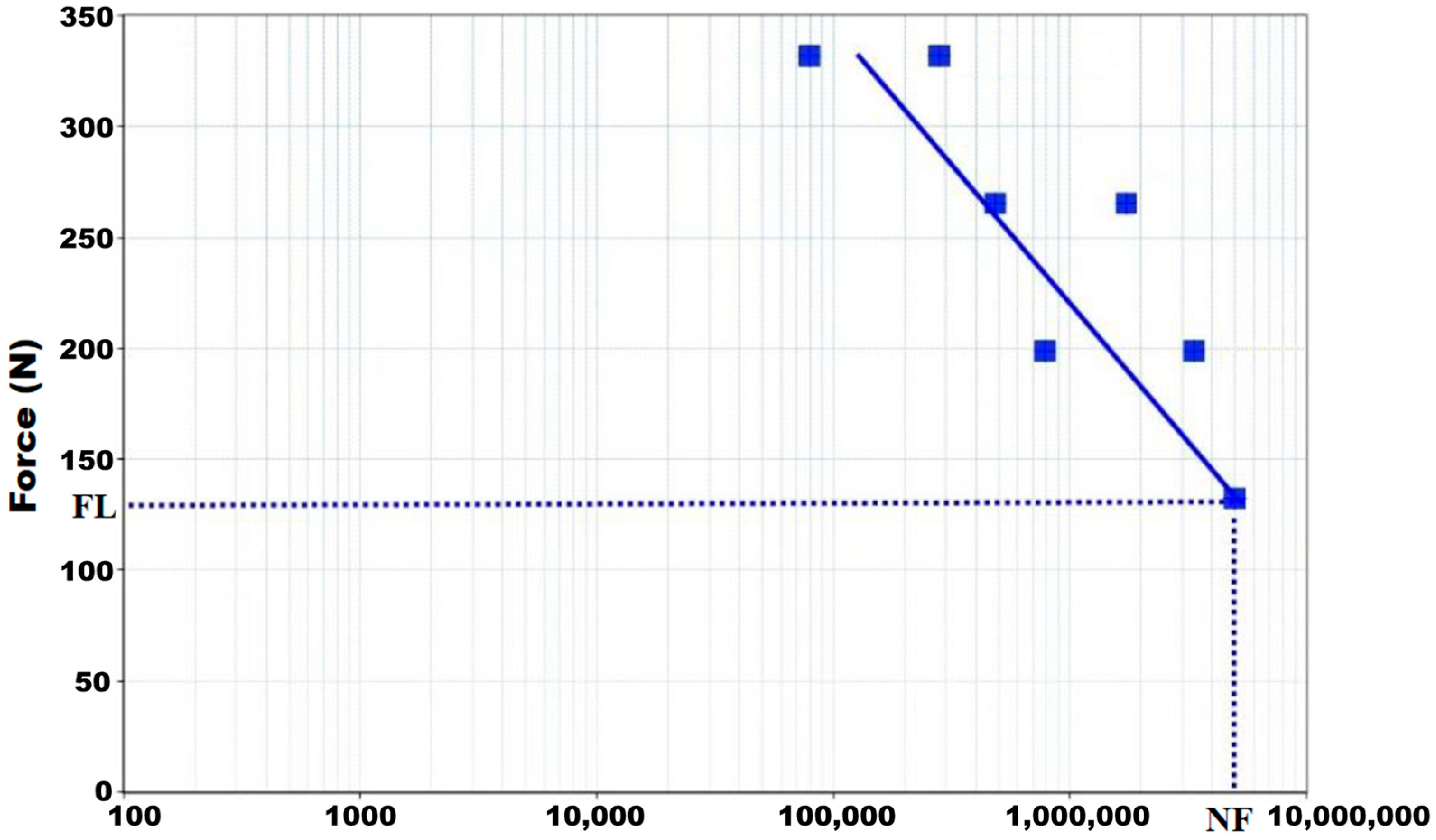
| Maximum Applied Load (N) | Number of Cycles |
|---|---|
| 417.70 | 79,423 |
| 331.60 | 280,841 |
| 265.30 | 487,551 |
| 223.40 | 1,731,994 |
| 199.00 | 783,023 |
| 167.50 | 3,351,847 |
| 132.60 | 5,000,000 |
Disclaimer/Publisher’s Note: The statements, opinions and data contained in all publications are solely those of the individual author(s) and contributor(s) and not of MDPI and/or the editor(s). MDPI and/or the editor(s) disclaim responsibility for any injury to people or property resulting from any ideas, methods, instructions or products referred to in the content. |
© 2023 by the authors. Licensee MDPI, Basel, Switzerland. This article is an open access article distributed under the terms and conditions of the Creative Commons Attribution (CC BY) license (https://creativecommons.org/licenses/by/4.0/).
Share and Cite
Lovera-Prado, K.; Vanaclocha, V.; Atienza, C.M.; Vanaclocha, A.; Jordá-Gómez, P.; Saiz-Sapena, N.; Vanaclocha, L. Barbed Dental Ti6Al4V Alloy Screw: Design and Bench Testing. Materials 2023, 16, 2228. https://doi.org/10.3390/ma16062228
Lovera-Prado K, Vanaclocha V, Atienza CM, Vanaclocha A, Jordá-Gómez P, Saiz-Sapena N, Vanaclocha L. Barbed Dental Ti6Al4V Alloy Screw: Design and Bench Testing. Materials. 2023; 16(6):2228. https://doi.org/10.3390/ma16062228
Chicago/Turabian StyleLovera-Prado, Keila, Vicente Vanaclocha, Carlos M. Atienza, Amparo Vanaclocha, Pablo Jordá-Gómez, Nieves Saiz-Sapena, and Leyre Vanaclocha. 2023. "Barbed Dental Ti6Al4V Alloy Screw: Design and Bench Testing" Materials 16, no. 6: 2228. https://doi.org/10.3390/ma16062228