Computational Analysis of Liquid Hydrogen Storage Tanks for Aircraft Applications
Abstract
1. Introduction
2. Materials and Methods
- (a)
- The tank configuration is selected to consist of the following three (3) structural components:
- An inner shell that is in touch with the LH2 (commonly mentioned in the literature as “liner”), made of an aluminum alloy. The reason a metallic shell is selected, compared to the other material category that could possibly be incorporated, that of composite materials, is that metallic materials exhibit a more efficient behavior in terms of hydrogen diffusion through their microstructure and of property degradation due to embrittlement when in contact with hydrogen. The possibility of using a combination of metallic and composite shell was not studied, due to the danger for catastrophic failure arising from the different stress field in their interface, which is a result of the much different coefficients of thermal expansion (CTEs) that these two material categories exhibit.
- Insulating material made of polyurethane (PUR) foam, which is characterized as efficient and well-established in terms of knowledge of its mechanical and thermal properties and its general behavior, as well as with low cost and satisfactory thermal conductivity [25].
- An outer shell made of layers of composite material to save mass, since this outer shell of composite material mainly plays the role of protecting the insulating material from external loads that are likely to cause a catastrophic failure.
- (b)
- The tanks under consideration are chosen to belong to the “non-integral” category, i.e., not to be part of the aircraft structure but to function simply as LH2 storage containers (pressure vessels). The reason for this choice is that the special characteristics of the thermal and structural behavior of a large variety of tank configurations could be highlighted, regardless of any specific aircraft design in which they are intended for use. Therefore, two additional issues, which are clarified below, are mentioned:
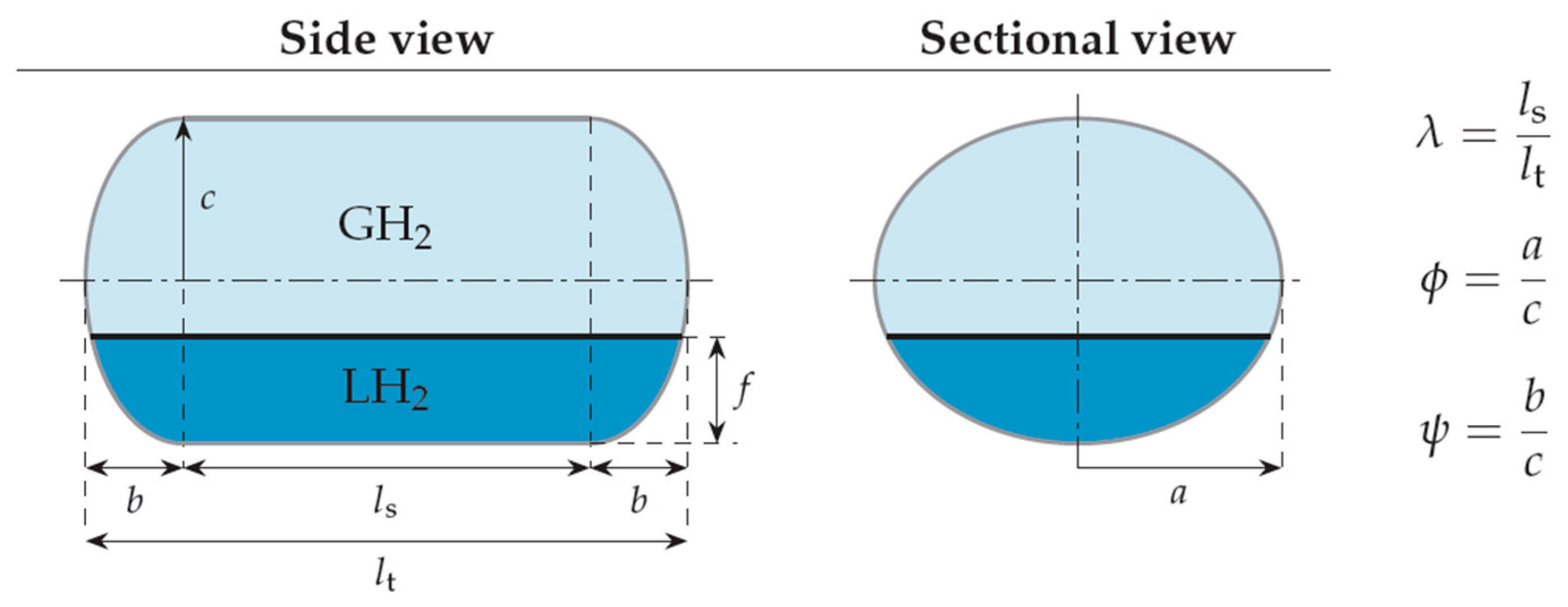
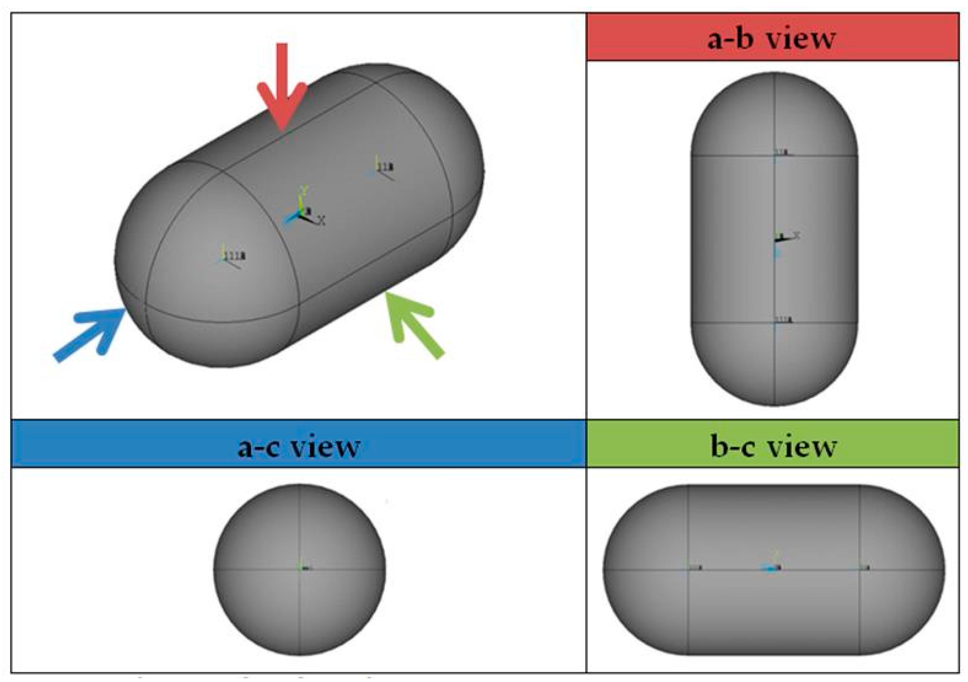
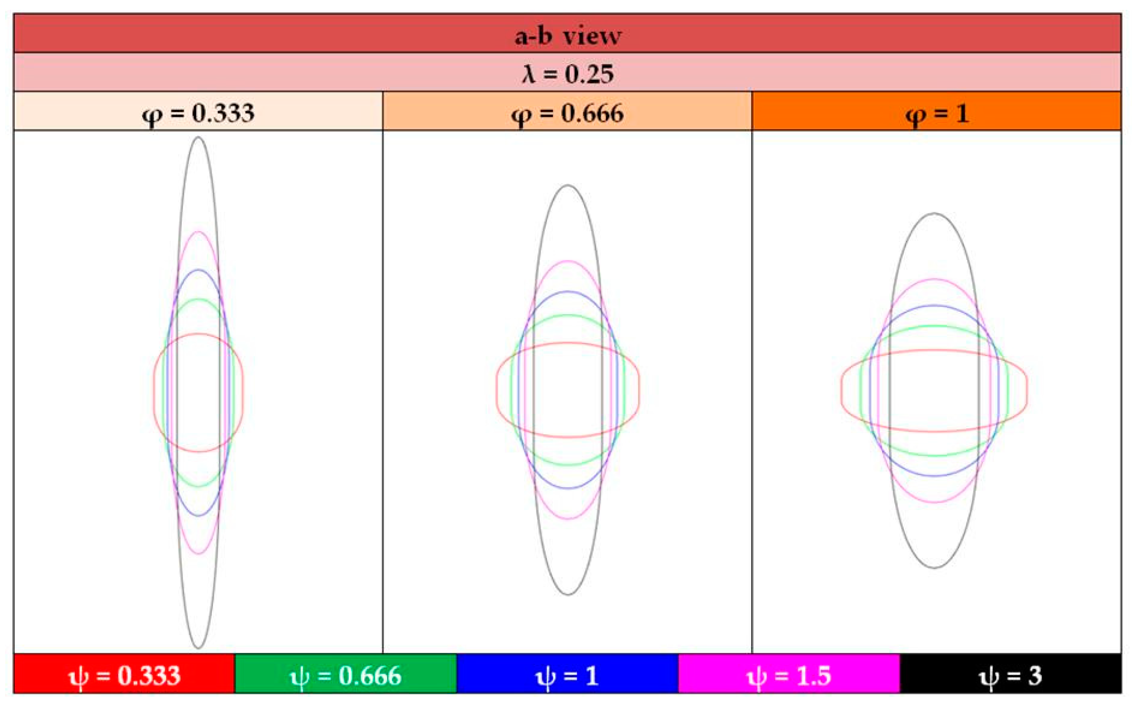
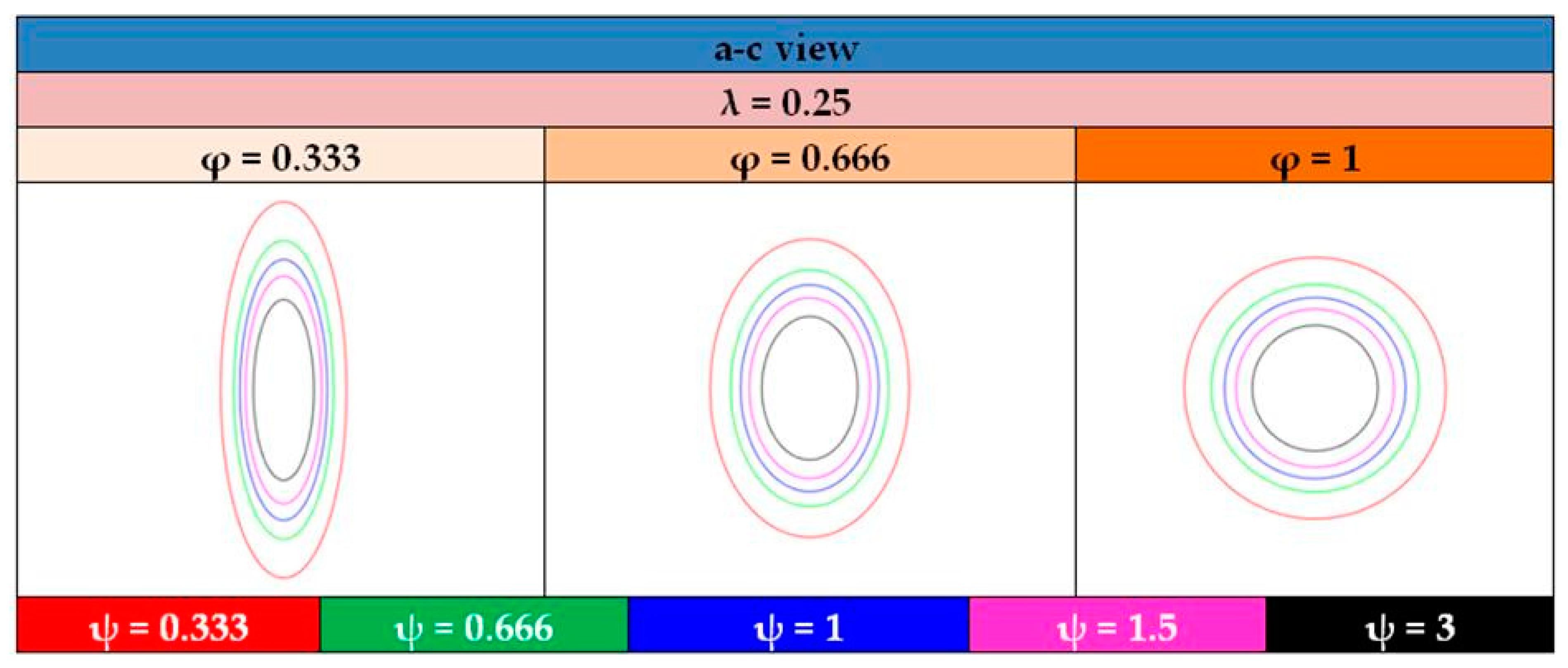
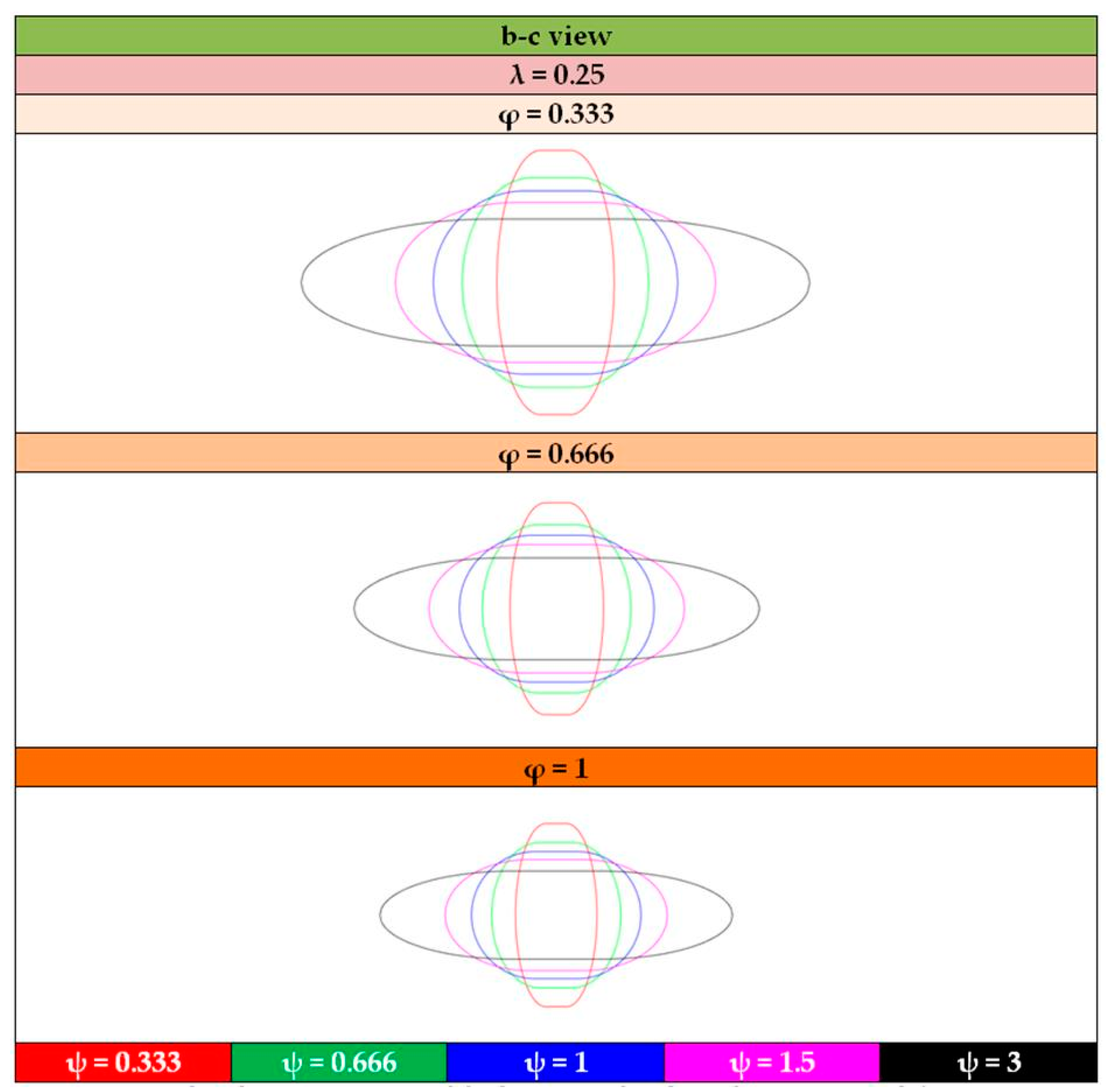
- The shape of the considered tanks. To produce all of the tank geometries considered, the method of triaxially symmetric tank geometries followed by Winnefeld et al. [5] was adopted. According to it, three (3) characteristic tank size ratios, λ, φ and ψ, are enough to describe its shape, as shown in Figure 1. These ratios are connected to the dimensions a, b and c of Figure 1, which are emphasized as being the semi-axes of three (3) ellipses (a–b, a–c, b–c), which, together with the length of the central part of the tank, ls, completely describe the tank.
- •
- The temperature and pressure conditions that apply inside and outside the tank and constitute the thermal and structural loads of the tanks under investigation, as “non-integral”, are the only ones they undergo (in contrast to the integral ones, they do not undergo the aerodynamic loads that the aircraft structure (fuselage and wings) receives). The temperature of the hydrogen is therefore taken to be equal to −253 °C (20 K), while the pressure in the volume enclosed by the inner shell is equal to 170 kPa [27]. The temperature of the external environment is taken, indicatively and by no means limiting, as equal to 10 °C (283 K).
- (c)
- As far as the thermal aspect of the issue is concerned, heat transfer between the external tank environment and the hydrogen enclosed in the inner tank shell is governed by all three (3) forms of heat transfer:
- Heat transfer between the external environment and the composite shell due to radiation.
- Heat transfer between the external environment and the composite material shell due to convection. For the purposes of this work, a value of 10 W/m2 K was taken, within the typical range of convection coefficients for free air flow (2.5–25 W/m2 K, [28]).
- Heat transfer between the composite shell and the insulating material, as well as between the insulating material and the aluminum shell due to conduction.
- Heat transfer between the aluminum shell and the hydrogen, either in its liquid or gaseous form, due to convection. In this case, it is necessary to determine two different convection coefficients, one for gaseous hydrogen and one for liquid, the values of which are determined as follows [29]:
- Hydrogen gas: 1.4587 W/m2 K
- Liquid hydrogen: 2.1827 W/m2 K
- (d)
- Regarding the structural aspect, in addition to the 170 kPa pressure previously mentioned to exist inside the inner aluminum shell, additional stress is created by the temperature distribution through all the tank components. This distribution is expected to show large variations, since, as mentioned above, the temperature in the tank interior is equal to −253 °C (20 K), while the external environment was considered to be 10 °C (283 K). These temperatures, through the coefficients of thermal expansion (CTEs) of the tank component materials, create thermal stresses that are added to the mechanical stresses due to pressure in the tank interior. On the matter of possible tank structural supports, it is remarked that the tanks under investigation are not considered to be installed in a specific aircraft structure, but instead they are supposed to be simply resting on the ground, without suppressing the displacement of any specific part of it, in order to exhibit the unique characteristics of each tank configuration, unaffected by possible stress concentrations or other influence due to complex support conditions.
- (e)
- In regard to the expression of the criteria according to which the thermal and structural behaviors of the tanks are assessed:
- For the thermal behavior, the achievement of a specific vaporization rate of the liquid hydrogen (boil-off rate) is defined as a criterion, the desired value of which is chosen before solving the problem. Through the following Equation (1) [29], this vaporization rate is connected to the maximum allowed heat flow between the hydrogen and the external tank environment.
- is the total heat flow between the LH2 inside the tank and the external environment (W)
- is the mass of LH2 inside the tank, which is calculated as the product of the LH2 volume (determined by the tank inner shell dimensions and the percentage of fullness of the tank) and its density, (=71 kg/m3) (Table 1).
- For the structural behavior, a separate criterion is defined for each of the tank components:
- For the aluminum inner shell, the Von Mises stress criterion is selected, with the critical temperature-dependent value obtained from experimental results published in the literature, as designated in the next paragraphs.
- For the PUR foam insulation material, the Tsai–Wu index criterion is chosen, which is built into the library of the software used to perform the analyses, and which has been demonstrated to be valid for the case of a corresponding type of foam (polyvinylchloride, PVC) [30].
- For the composite material outer shell, two (2) different criteria from those available in the software [31] are selected, the Tsai–Wu and the Hashin ones.
- (a)
- Calculation, through repeated iterative analyses, of the insulation thickness required to achieve the tank heat flow rate dictated by the selected hydrogen vaporization rate (boil-off rate), by performing thermal analysis, taking into account the heat transfer modes mentioned above, as well as the temperature conditions inside and outside the tank as boundary conditions.
- (b)
- Saving the temperature distribution calculated during the solution of the thermal analysis at all nodes of the tank and introducing them as boundary conditions in the structural analysis, along with the pressure condition of 170 kPa inside the tank.
- (c)
- Keeping the thickness of the insulating material and the composite material outer shell constant, calculation through iterative analyses of the thickness of the aluminum inner shell until the Von Mises criterion is satisfied, which acts as an evaluation criterion for the aluminum alloy. At the same time, confirmation that both the insulating material and composite shell evaluation criteria do not indicate any failure in these tank components.
- The homogeneous version, where the element is considered to be of isotropic behavior and, as such, is used to model isotropic materials.
- The layered version, where the element is internally divided in multiple layers, and by selecting a different for each layer axes system, anisotropic materials are modelled.
3. Results
3.1. Convergence Study
- Regarding the in-plane mesh size (length and width)
- ○
- 0.15 m (coarse mesh)
- ○
- 0.1 m (medium mesh)
- ○
- 0.05 m (fine mesh)
- Regarding the through-thickness mesh size
- ○
- For the elements of the aluminum inner shell and the composite outer shell: one element (due to small thickness)
- ○
- For the elements of the insulation polyurethane foam layer:
- ▪
- four elements through thickness (coarse mesh)
- ▪
- six elements through thickness (medium mesh)
- ▪
- eight elements through thickness (fine mesh)
- (1)
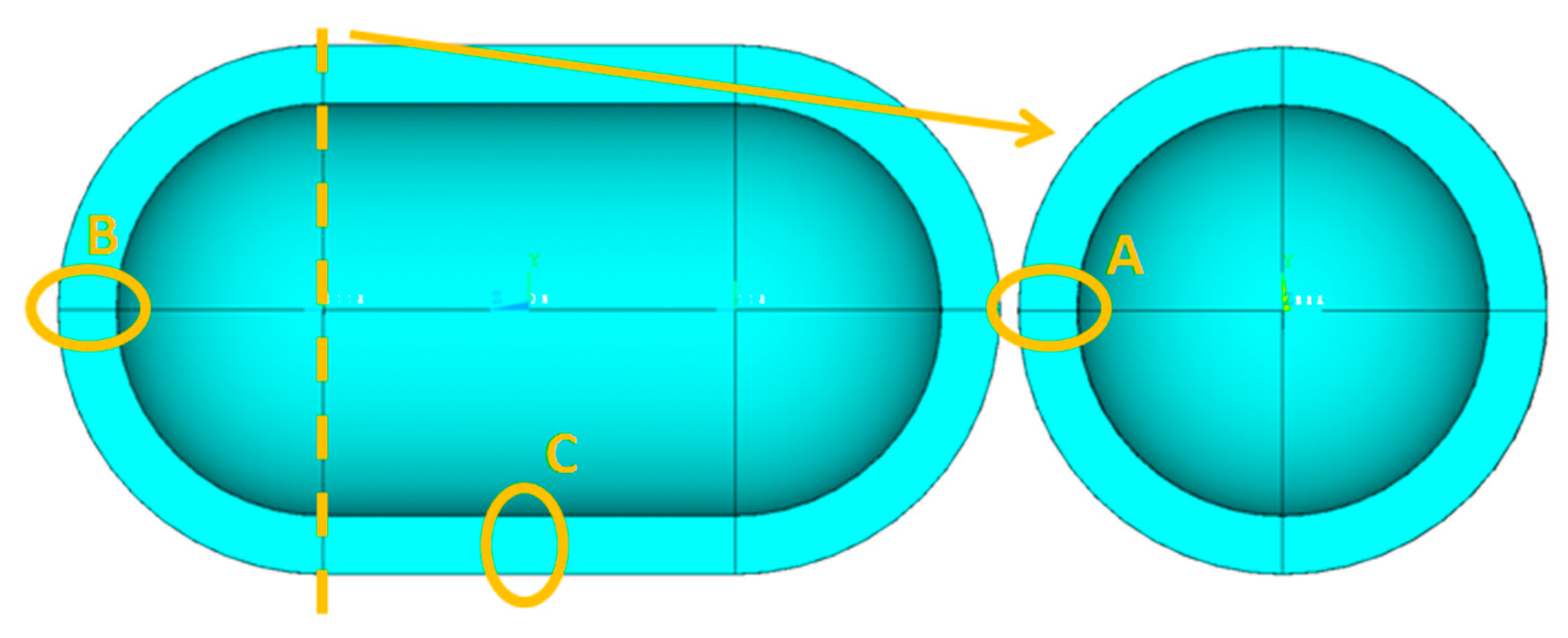
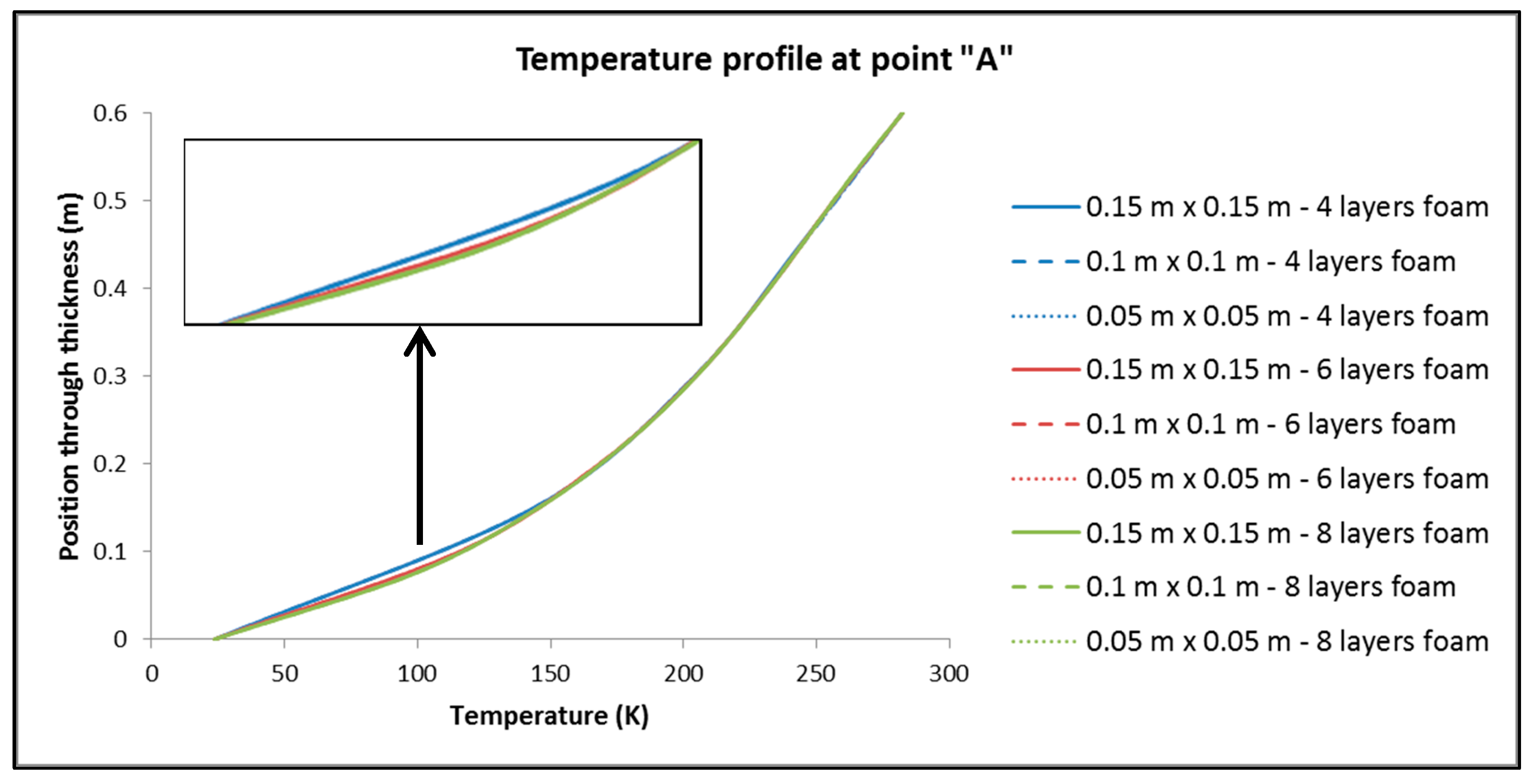
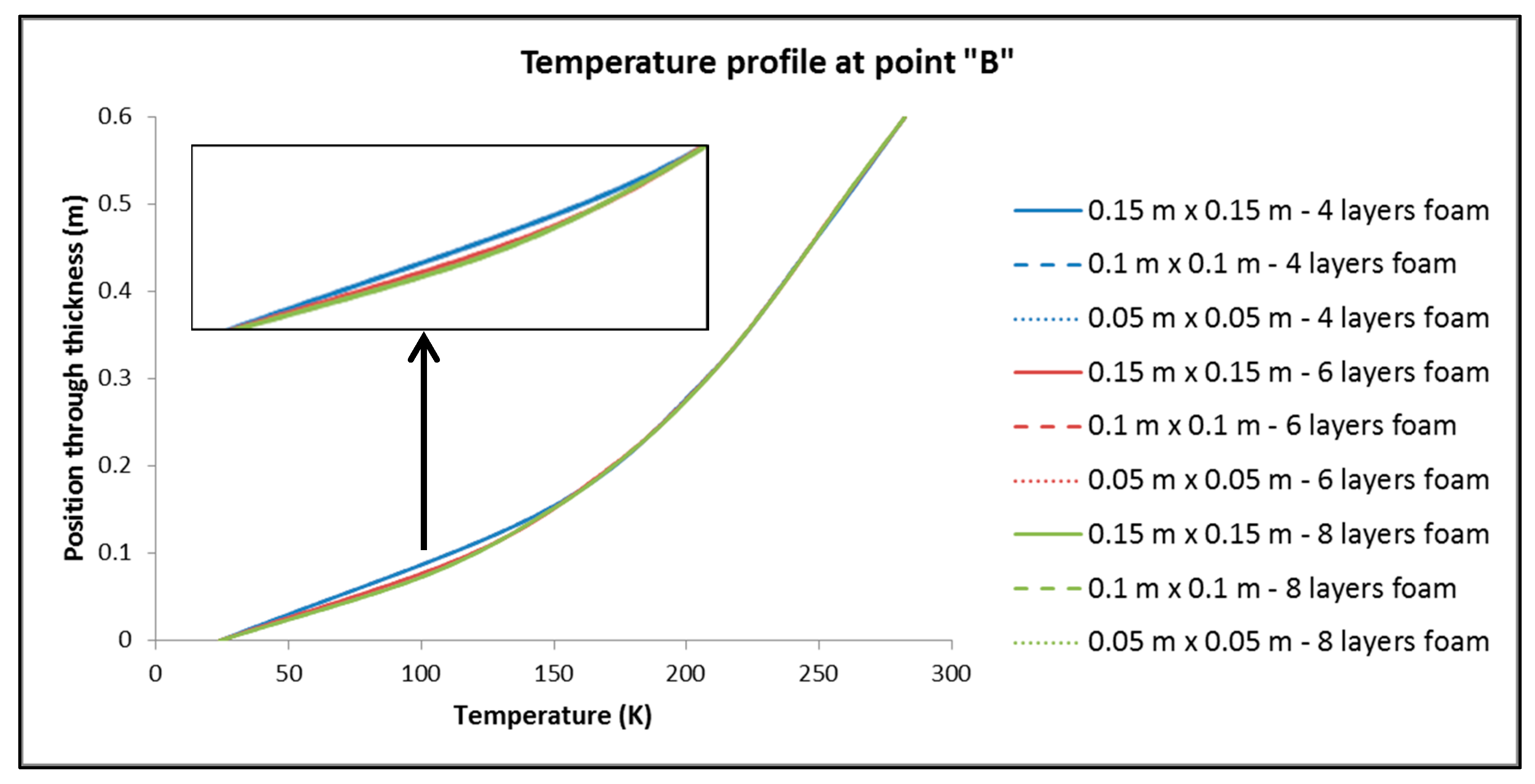
- For the values of the minimum and maximum temperature overall in the tank, it is observed that only a negligible effect, if not zero, causes both the change in the dimensions of the elements in the plane and the number of elements in the thickness of the insulation.
- (2)
- For the size of the heat output, Q, of the tank:
- By keeping the number of elements constant across the thickness of the insulation, dimension variation of the elements has no significant influence on Q.
- On the contrary, by keeping the dimensions of the elements constant and varying their number by the thickness of the insulation, it is found that the changes are more significant than in sub-case (a).
3.2. Study of the Tanks Relative to the Height of LH2
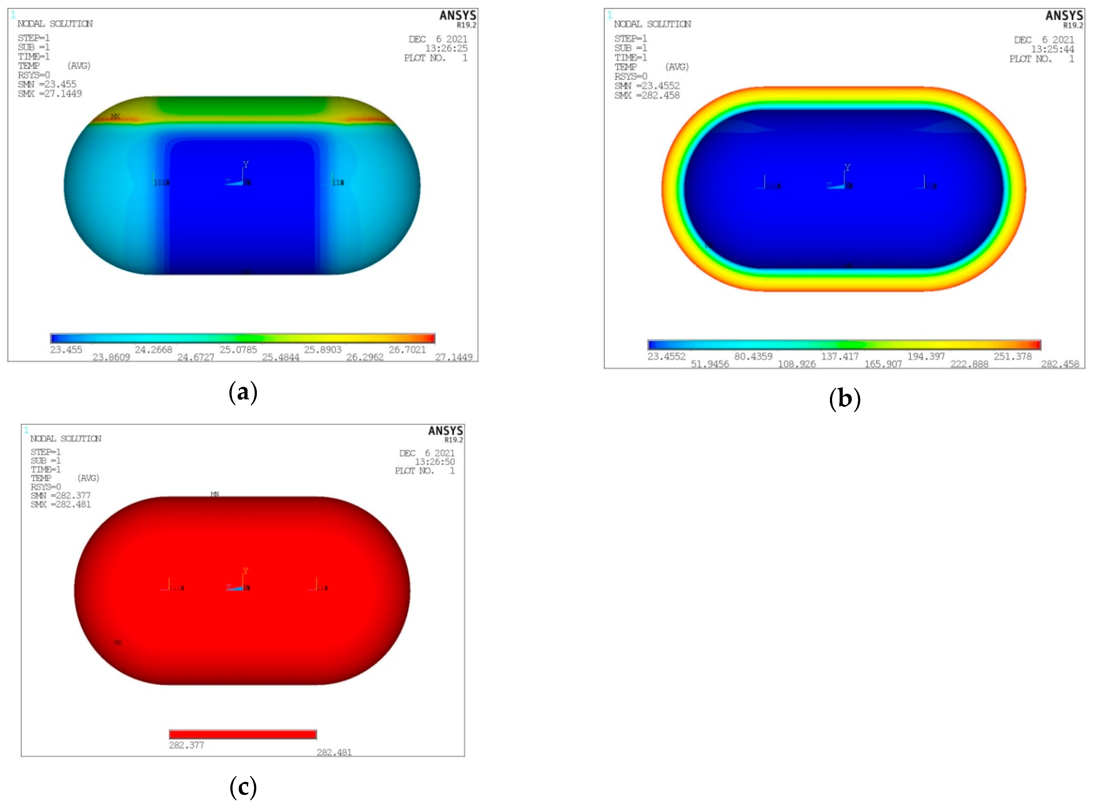
- Temperature distribution for the three tank components (inner aluminum shell, insulating material, outer composite shell) (Figure 9).
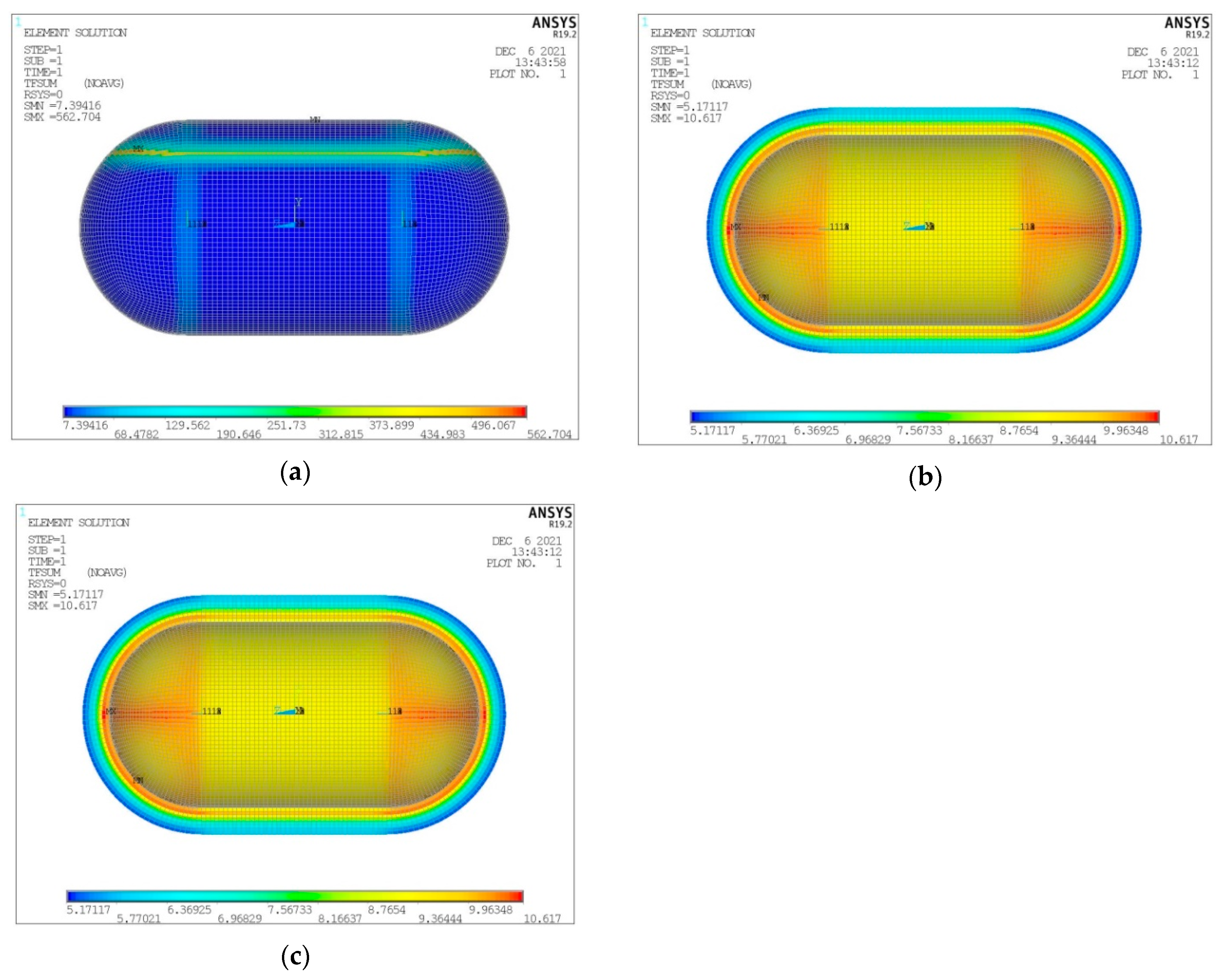
- Heat flux (heat flow per unit area) for the three tank components (inner aluminum shell, insulating material, outer aluminum shell) (Figure 10).
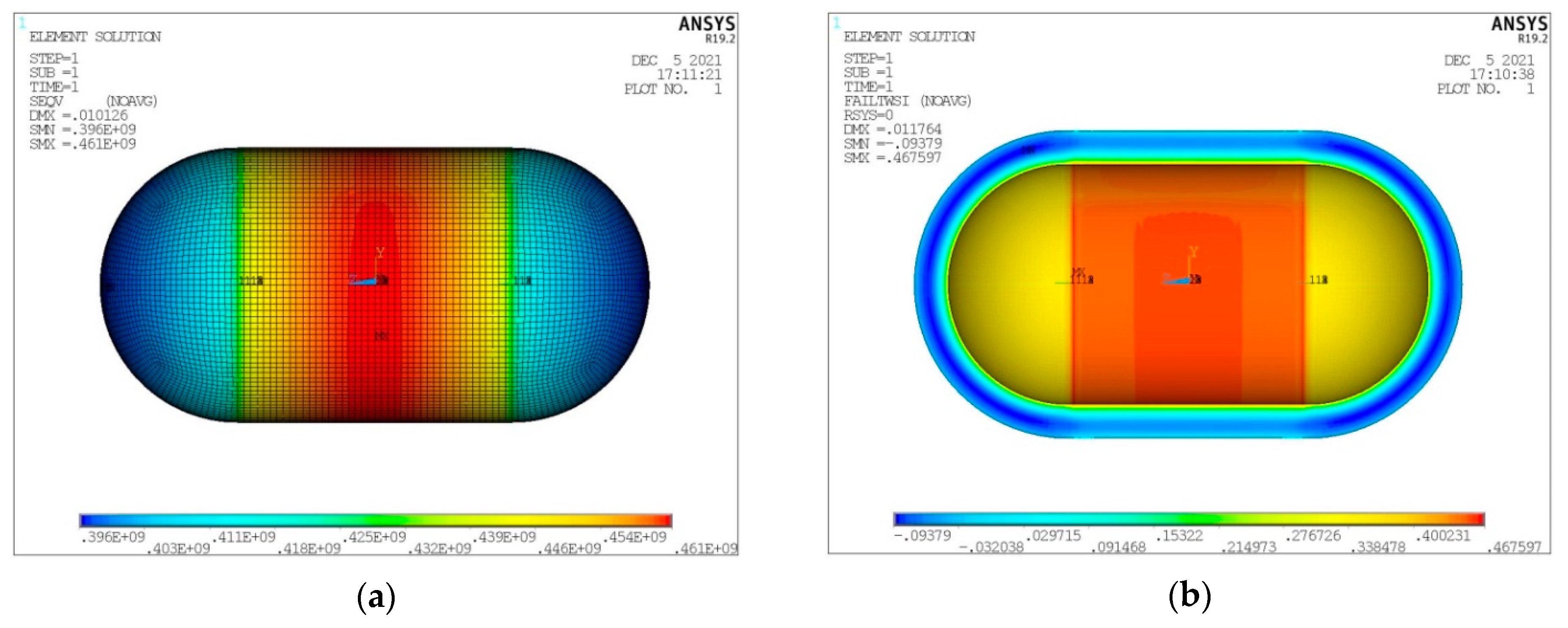
- Von Mises stress on the inner aluminum shell (Figure 11a).
- Tsai–Wu index on the insulating material (Figure 11b).
- Tsai–Wu index on the outer composite material shell (Figure 12a).
- Hashin fibre failure criterion on the outer composite material shell (Figure 12b).
- Hashin matrix failure criterion on the outer composite material shell (Figure 12c).
3.3. Study of the Tanks under Constant Volume of LH2
- For the thermal behavior of the tank, the LH2 vaporization rate (boil-off rate) is taken as a criterion, which is a direct function of the heat flow between the LH2 and the tank external environment, based in Equation (1). The boil-off rate chosen in this particular case is equal to 0.1%/h, based on those mentioned by Mital et al. [33] for the case of aviation applications. Therefore, considering for the tanks of this Section an LH2 filling percentage of 93% (the maximum limit set, as already mentioned in Section 2), and a volume of the inner shell of 100 m3, the heat flow maximum allowable limit to achieve the selected boil-off rate is calculated equal to 845 W.
- For the structural behavior of the tank, as previously, the Von Mises stress criterion for the inner aluminum shell, the Tsai–Wu index criterion for the insulating PUR foam and both the Tsai–Wu index and Hashin criteria for the outer composite material shell are used.
- Iterative thermal analysis of the tank in order to determine the insulating material thickness required to marginally achieve the heat flow limit of 845 W (the insulating material thickness is taken as constant in every point of the tank).
- Iterative structural analysis of the tank, by incorporating the temperature distribution extracted by the thermal analysis in order to create the thermal stresses and additionally applying an internal pressure of 170 kPa, in order to determine the inner aluminum shell thickness that marginally achieves the Von Mises stress criterion. In parallel, the insulating PUR foam and the outer composite material shell are also evaluated for their structural integrity by means of the structural criteria mentioned above. It is noted that, in order to avoid complexity matters, the thickness of the outer composite shell is kept constant, with the value defined in Section 2, and it is only evaluated against failure. Table 4 includes details of the tank configurations considered in this section.
- The total surface of the inner aluminum shell based on the characteristic dimensions ls, lt, a, b and c. (Figure 17).
- The necessary insulating PUR foam thickness in order to satisfy the requirement for a boil-off rate with a value of 0.1%/h from which the maximum allowed heat flow between the tank interior and the external environment is calculated equal to 845 W (Figure 18).
- The total mass of the insulating material, which is affected by both the total surface of the inner aluminum shell and the insulating material thickness (Figure 19).
- The thickness of the inner aluminum shell in order to satisfy the Von Mises stress criterion, according to which its structural integrity is assessed (Figure 20).
- The total tank mass (inner shell, insulating material, outer shell) (Figure 21).
- Regarding the minimum insulating material thickness that is calculated in order to maintain the LH2 vaporization rate (boil-off rate) at a level of 0.1%/h (Figure 18), as it has been defined, it is concluded that, in general, the required thickness is connected to the surface of the inner aluminum shell. More specifically, the larger the surface, the thicker the insulating material that needs to be applied in order to ensure the proper heat flow that corresponds to the specified boil-off rate of 0.1%/h. This phenomenon is generally expected, because the heat transfer mechanism of convection occurring between the hydrogen in the tank interior and the inner aluminum shell is dependent on the total surface of solid–fluid interaction. Exceptions to this trend are the tanks with geometric ratios λ = 0.75, φ = 0.333, ψ = 1.5 and λ = 0.75, φ = 0.333, ψ = 3, for which it is noted that the insulating material thickness is kept almost steady compared to the previous one (λ = 0.75, φ = 0.333, ψ = 1). This is attributed to the fact that for the specific two tanks the required insulation thickness that ensures the proper boil-off rate is very close to the critical insulation thickness beyond which any further increase would also increase, instead of reducing, the heat flow; this phenomenon is attributed to the fact that the outer composite shell surface is increased so much due to the increased insulation thickness that results in an increased heat flow due to convection between the outer shell and the external environment.
- As for the insulating material mass, which is calculated according to the already-calculated insulation thickness (Figure 19), it is observed that the distribution is strictly following the corresponding one of the inner aluminum shell surface, as expected. In this case as well, exceptions are the two tank configurations (λ = 0.75, φ = 0.333, ψ = 1.5 and λ = 0.75, φ = 0.333, ψ = 3) mentioned, where the distribution slope is affected by the straightening of the thickness distribution, which was explained in the previous paragraph.
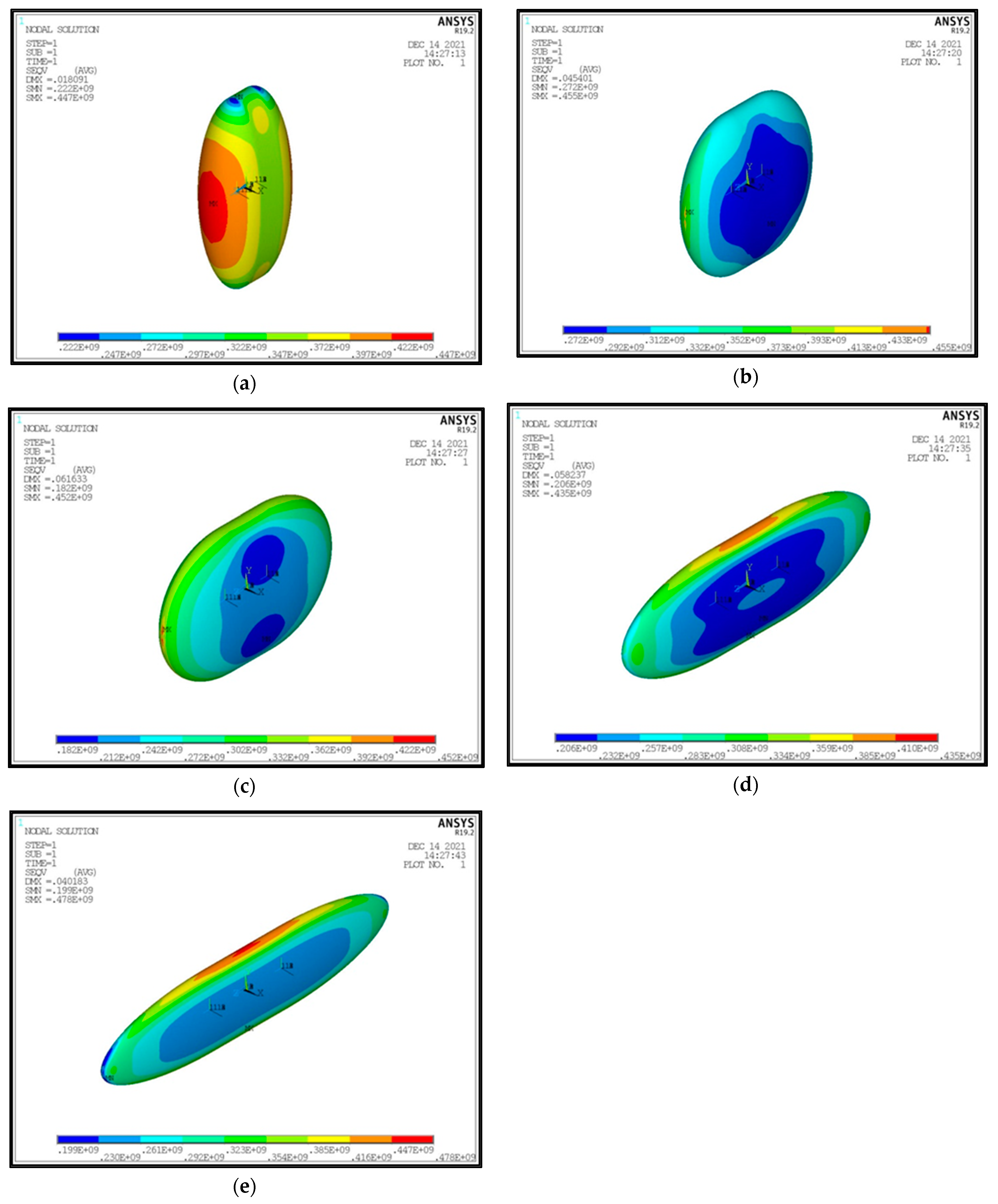
- Concerning the required thickness of the inner aluminum shell to satisfy the Von Mises criterion (Figure 20), based on which its structural strength is evaluated, it is observed that this does not show any specific pattern between the different tanks. This is due to the fact that overall the arrangement of the examined tanks is such that their structural behavior is quite complex, and certainly non-linear, due to the fact that the thermal and mechanical properties of the materials used are a function of temperature. Specifically, characteristic points of the diagrams that are worth highlighting, and concern areas with a sharp change in the distribution between the different configurations, e.g., for the tanks with λ = 0.25 and φ = 0.333: during the transition from ψ = 1 to ψ = 1.5 (Figure 20), a sharp change in the distribution is observed, which is due to the fact that the point where the maximum Von Mises stress is observed (the most critical area of the aluminum shell) shifts from one point of the tank to another. A representative depiction of this phenomenon is included in Figure 23.
- Concerning the total mass of the tank (Figure 21), it is already clear from the above that it follows the distribution of the mass of the insulating material, since this constitutes the overwhelmingly greater percentage of the total mass of the tanks, since in all cases this percentage is within the range 87–95%.
- Finally, regarding the gravimetric efficiency of the tanks (Figure 22), due to the domination of the insulating material mass, it follows a reverse distribution and exhibits a range of values between 15 and 54%.
4. Discussion and Results
Author Contributions
Funding
Institutional Review Board Statement
Informed Consent Statement
Data Availability Statement
Conflicts of Interest
References
- Airbus Global Market Forecast 2022–2041. Available online: https://www.airbus.com/en/products-services/commercial-aircraft/market/global-market-forecast (accessed on 28 August 2022).
- Boeing Commercial Market Outlook 2022–2041. Available online: https://www.boeing.com/commercial/market/commercial-market-outlook/index.page (accessed on 28 August 2022).
- European Green Deal Announcement. Available online: https://ec.europa.eu/info/strategy/priorities-2019-2024/european-green-deal_en (accessed on 28 August 2022).
- Hydrogen powered aviation—A Fact-Based Study of Hydrogen Technology, Economics and Climate Impact by 2050. Available online: https://www.fch.europa.eu/sites/default/files/FCH%20Docs/20200507_Hydrogen%20Powered%20Aviation%20report_FINAL%20web%20%28ID%208706035%29.pdf (accessed on 28 August 2022).
- Winnefeld, C.; Kadyk, T.; Bensmann, B.; Krewer, U.; Hanke-Rauschenbach, R. Modelling and designing cryogenic hydrogen tanks for future aircraft applications. Energies 2018, 11, 105. [Google Scholar] [CrossRef]
- Meyer, M.L.; Chato, D.J.; Plachta, D.W.; Zimmerli, G.A.; Barsi, S.J.; Van Dresar, N.T.; Moder, J.P. Mastering cryogenic propellants. J. Aerosp. Eng. 2013, 26, 343–351. [Google Scholar] [CrossRef]
- Cecere, D.; Giacomazzi, E.; Ingenito, A. A review on hydrogen industrial aerospace applications. Int. J. Hydrog. Energy 2014, 39, 10731–10747. [Google Scholar] [CrossRef]
- Winter, C.J. Hydrogen in high-speed air transportation. Int. J. Hydrog. Energy 1990, 15, 579–595. [Google Scholar] [CrossRef]
- NASA. Liquid Hydrogen as a Propulsion Fuel, 1945–1959. Available online: https://history.nasa.gov/SP-4404/ch8-3.htm (accessed on 28 August 2022).
- Westenberger, A. Cryoplane project presentation. In Proceedings of the H2 Expo, Hamburg, Germany, 28–29 June 2003. [Google Scholar]
- Liquid Hydrogen Fuelled Aircraft—System Analysis (Cryoplane Project); Technical Report, Contract Νο G4RD-CT-2000-00192, Project No GRD1-1999-10014; Airbus: Deutshand, Germany, 2003.
- Verstraete, D.; Hendrick, P.; Pilidis, P.; Ramsden, K. Hydrogen fuel tanks for subsonic transport aircraft. Int. J. Hydrog. Energy 2010, 35, 11085–11098. [Google Scholar] [CrossRef]
- Silberhorn, D.; Atanasov, G.; Walther, J.N.; Zill, T. Assessment of hydrogen fuel tank integration at aircraft level. In Proceedings of the Deutscher Luft und Raumafahrtkongress, Darmstadt, Germany, 30 September–2 October 2019. [Google Scholar]
- Onorato, G. Fuel Tank Integration for Hydrogen Airliners. Master’s Thesis, TU Delft, Delft, The Netherlands, 2021. [Google Scholar]
- Seeckt, K.; Heinze, W.; Scholz, D. Hydrogen powered freighter aircraft—The final results of the Green Freighter Project. In Proceedings of the 27th International Congress of the Aeronautical Sciences, Nice, France, 19–24 September 2010. [Google Scholar]
- Smith, H. Airframe integration for an LH2 hybrid-electric propulsion system. Aircr. Eng. Aerosp. Techmol. 2014, 86, 562–567. [Google Scholar] [CrossRef]
- Rao, A.G. Advanced Hybrid Engines for Aircraft Development (AHEAD); Project Final Report; TU Delft: Delft, The Netherlands, 2015. [Google Scholar]
- Goldberg, C. Techno-Economic, Environment and Risk Analysis of an Aircraft Concept with Turbo-Electric Distributed Propulsion. Ph.D. Thesis, Cranfield University, Cranfield, UK, 2017. [Google Scholar]
- Dietl, T.; Karger, J.; Kaupe, K.; Pfemeter, A.; Weber, P.; Zakrzewski, A.; Strohmayer, A. POLARIS Future Aircraft Design Concept; University of Stuttgart: Stuttgart, Germany, 2018. [Google Scholar]
- Van Woensel, C.W.C. Integration of a Liquid Hydrogen Fuel Tank into the Concept of the Flying-V. Master’s Thesis, TU Delft, Delft, The Netherlands, 2021. [Google Scholar]
- Tapeinos, I.G.; Koussios, S.; Groves, R.M. Design and analysis of a multi-cell subscale tank for liquid hydrogen storage. Int. J. Hydrog. Energy 2016, 41, 3676–3688. [Google Scholar] [CrossRef]
- Tapeinos, I.G.; Zarouchas, D.S.; Bergsma, O.K.; Koussios, S.; Benedictus, R. Evaluation of the mechanical performance of a composite multi-cell tank for cryogenic storage: Part I—Tank pressure window based on progressive failure analysis. Int. J. Hydrog. Energy 2019, 44, 3917–3930. [Google Scholar] [CrossRef]
- Tapeinos, I.G.; Rajabzadeh, A.; Zarouchas, D.S.; Bergsma, O.K.; Koussios, S.; Benedictus, R. Evaluation of the mechanical performance of a composite multi-cell tank for cryogenic storage: Part II—Experimental assessment. Int. J. Hydrog. Energy 2019, 44, 3931–3943. [Google Scholar] [CrossRef]
- Gomez, A.; Smith, H. Liquid hydrogen fuel tanks for commercial aviation: Structural sizing and stress analysis. Aerosp. Sci. Technol. 2019, 95, 105438. [Google Scholar] [CrossRef]
- Mital, S.; Gyekenyesi, J.; Arnold, S.; Sullivan, R.; Manderscheid, J.; Murthy, P. Review of Current State of the Art and Key Design Issues with Potential Solutions for Liquid Hydrogen Cryogenic Storage Tank Structures for Aircraft Applications. NASA-TM-2006-214346. 2006. Available online: https://ntrs.nasa.gov/citations/20060056194 (accessed on 9 March 2023).
- Colozza, A.J.; Kohut, L. Hydrogen Storage for Aircraft Applications Overview. NASA CR-2002-211867. 2002. Available online: https://ntrs.nasa.gov/citations/20020085127 (accessed on 9 March 2023).
- Brewer, G.D. Hydrogen Aircraft Technology, 1st ed.; CRC Press: Boca Raton, FL, USA, 1991. [Google Scholar]
- Cengel, Y. Heat and Mass Transfer: A Practical Approach, 3rd ed.; McGraw-Hill: New York, NY, USA, 2006. [Google Scholar]
- Dagsever, F. The Design of Composite LH2 Tank for Aircraft Operations. Master’s Thesis, Cranfield University, Cranfield, UK, 2020. [Google Scholar]
- Gdoutos, E.E.; Daniel, I.M.; Wang, K.-A. Multiaxial characterization and modeling of a PVC cellular foam. J. Thermoplast. Compos. Mater. 2001, 14, 365–373. [Google Scholar] [CrossRef]
- ANSYS©. Mechanical APDL; Release 19.2; ANSYS Inc.: Canonsburg, PE, USA, 2019. [Google Scholar]
- Simon, N.J.; Drexler, E.S.; Reed, R.P. Review of Cryogenic Mechanical and Thermal Properties of Al-Li Alloys and Alloy 2219; Technical Report. Contract No 5081-352-0425. 1984. Available online: https://apps.dtic.mil/sti/pdfs/ADA229231.pdf (accessed on 9 March 2023).
- Sparks, L.L.; Arvidson, J.M. Thermal and Mechanical Properties of Polyurethane Foams and a Survey of Insulating Concretes at Cryogenic Temperatures. Gas Research Institute. Grant No 5081-352-0425. 1984. Available online: https://apps.dtic.mil/sti/pdfs/ADA302346.pdf (accessed on 9 March 2023).
- Mangolg, J.; Silberhorn, D.; Moebs, N.; Dzikus, N.; Hoelzen, J.; Zill, T.; Strohmayer, A. Refueling of LH2 aircraft-assessment of turnaround procedures and aircraft design implication. Energies 2022, 15, 2475. [Google Scholar] [CrossRef]
- Al Ghafri, S.Z.S.; Swanger, A.; Jusko, V.; Siahvashi, A.; Perez, F.; Johns, M.L.; May, E.F. Modelling of liquid hydrogen boil-off. Energies 2022, 15, 1149. [Google Scholar] [CrossRef]






| Property | LH2 | Jet-A (Kerosene) |
|---|---|---|
| Energy content per unit mass (MJ/kg) | 120 | 42.8 |
| Energy content per unit volume (MJ/L) | 8.49 | 31.15 |
| Density (kg/m3) | 71 | 811 |
| Specific heat capacity (J/gK) | 9.69 | 1.98 |
| Specific heat of vaporization (J/kg) | 461,000 | 360,000 |
| Property | Value |
|---|---|
| Density, ρ | 1600 kg/m3 |
| Thermal conductivity, k | k11 = 3.972 W/mK, k22 = k33 = 0.3363 W/mK |
| Specific heat capacity, Cp | 1000 kg/m3 |
| Coefficient of thermal expansion, aii | a11 = −0.2 × 10⁻⁶ m/m/°K, α22 = α33 = 30 × 10−6 m/m/°K |
| Young’s modulus, Eii | E11 = 133 GPa, Ε22 = Ε33 = 9.13 GPa |
| Poisson vatio, vij | v12 = v13 = 0.3, v23 ≅ 0.3 |
| Shear modulus, Gij | G12 = G13 = 5.2 GPa, G23 ≅ 5.2 GPa |
| Ply longitudinal tensile strength, Xt | 2178.2 MPa |
| Ply longitudinal compressive strength, Yt | 91.7 MPa |
| Ply transvers tensile strength, Xc | 1783.5 MPa |
| Ply transverse compressive strength, Yc | 340.9 MPa |
| Ply in-plane shear strength, S | 129.1 MPa |
| Elements by Thickness | Element Size in Plane | Total Number of Elements | Q (W) | Tmin (K) | Tmax (K) |
|---|---|---|---|---|---|
| 4 | 0.15 m | 32,208 | 942.4 | 23.56 | 282.47 |
| 4 | 0.10 m | 75,888 | 943.9 | 23.56 | 282.47 |
| 4 | 0.05 m | 289,872 | 945.1 | 23.56 | 282.47 |
| 6 | 0.15 m | 42,944 | 923.6 | 23.48 | 282.48 |
| 6 | 0.10 m | 101,184 | 923.8 | 23.48 | 282.48 |
| 6 | 0.05 m | 386,496 | 924.5 | 23.48 | 282.48 |
| 8 | 0.15 m | 53,680 | 916.9 | 23.46 | 282.48 |
| 8 | 0.10 m | 126,480 | 916.4 | 23.45 | 282.48 |
| 8 | 0.05 m | 483,120 | 916.8 | 23.45 | 282.48 |
| λ | φ | ψ | lt (m) | ls (m) | a (m) | b (m) | c (m) |
|---|---|---|---|---|---|---|---|
| 0.25 | 0.333 | 0.333 | 4.649 | 1.162 | 1.743 | 1.743 | 5.236 |
| 0.666 | 7.380 | 1.845 | 1.384 | 2.768 | 4.156 | ||
| 1 | 9.677 | 2.419 | 1.208 | 3.629 | 3.629 | ||
| 1.5 | 12.681 | 3.170 | 1.056 | 4.755 | 3.170 | ||
| 3 | 20.130 | 5.032 | 0.838 | 7.549 | 2.516 | ||
| 0.666 | 0.333 | 3.690 | 0.923 | 2.768 | 1.384 | 4.156 | |
| 0.666 | 5.858 | 1.464 | 2.197 | 2.197 | 3.298 | ||
| 1 | 7.681 | 1.920 | 1.918 | 2.880 | 2.880 | ||
| 1.5 | 10.065 | 2.516 | 1.676 | 3.774 | 2.516 | ||
| 3 | 15.977 | 3.994 | 1.330 | 5.991 | 1.997 | ||
| 1 | 0.333 | 3.223 | 0.806 | 3.629 | 1.208 | 3.629 | |
| 0.666 | 5.116 | 1.279 | 2.880 | 1.918 | 2.880 | ||
| 1 | 6.708 | 1.677 | 2.515 | 2.515 | 2.515 | ||
| 1.5 | 8.790 | 2.197 | 2.197 | 3.296 | 2.197 | ||
| 3 | 13.953 | 3.488 | 1.744 | 5.232 | 1.744 | ||
| 0.5 | 0.333 | 0.333 | 5.882 | 2.941 | 1.471 | 1.471 | 4.416 |
| 0.666 | 9.337 | 4.669 | 1.167 | 2.334 | 3.505 | ||
| 1 | 12.243 | 6.122 | 1.019 | 3.061 | 3.061 | ||
| 1.5 | 16.043 | 8.022 | 0.890 | 4.011 | 2.674 | ||
| 3 | 25.467 | 12.734 | 0.707 | 6.367 | 2.122 | ||
| 0.666 | 0.333 | 4.669 | 2.334 | 2.334 | 1.167 | 3.505 | |
| 0.666 | 7.411 | 3.705 | 1.853 | 1.853 | 2.782 | ||
| 1 | 9.718 | 4.859 | 1.618 | 2.429 | 2.429 | ||
| 1.5 | 12.734 | 6.367 | 1.413 | 3.183 | 2.122 | ||
| 3 | 20.213 | 10.107 | 1.122 | 5.053 | 1.684 | ||
| 1 | 0.333 | 4.077 | 2.039 | 3.061 | 1.019 | 3.061 | |
| 0.666 | 6.472 | 3.236 | 2.429 | 1.618 | 2.429 | ||
| 1 | 8.486 | 4.243 | 2.122 | 2.122 | 2.122 | ||
| 1.5 | 11.120 | 5.560 | 1.853 | 2.780 | 1.853 | ||
| 3 | 17.652 | 8.826 | 1.471 | 4.413 | 1.471 | ||
| 0.75 | 0.333 | 0.333 | 9.045 | 6.784 | 1.131 | 1.131 | 3.395 |
| 0.666 | 14.358 | 10.769 | 0.897 | 1.795 | 2.695 | ||
| 1 | 18.827 | 14.121 | 0.784 | 2.353 | 2.353 | ||
| 1.5 | 24.671 | 18.503 | 0.685 | 3.084 | 2.056 | ||
| 3 | 39.163 | 29.372 | 0.543 | 4.895 | 1.632 | ||
| 0.666 | 0.333 | 7.179 | 5.384 | 1.795 | 0.897 | 2.695 | |
| 0.666 | 11.396 | 8.547 | 1.425 | 1.425 | 2.139 | ||
| 1 | 14.943 | 11.208 | 1.244 | 1.868 | 1.868 | ||
| 1.5 | 19.581 | 14.686 | 1.087 | 2.448 | 1.632 | ||
| 3 | 31.083 | 23.313 | 0.863 | 3.885 | 1.295 | ||
| 1 | 0.333 | 6.270 | 4.702 | 2.353 | 0.784 | 2.353 | |
| 0.666 | 9.952 | 7.464 | 1.868 | 1.244 | 1.868 | ||
| 1 | 13.050 | 9.787 | 1.631 | 1.631 | 1.631 | ||
| 1.5 | 17.100 | 12.825 | 1.425 | 2.138 | 1.425 | ||
| 3 | 27.145 | 20.359 | 1.131 | 3.393 | 1.131 |
Disclaimer/Publisher’s Note: The statements, opinions and data contained in all publications are solely those of the individual author(s) and contributor(s) and not of MDPI and/or the editor(s). MDPI and/or the editor(s) disclaim responsibility for any injury to people or property resulting from any ideas, methods, instructions or products referred to in the content. |
© 2023 by the authors. Licensee MDPI, Basel, Switzerland. This article is an open access article distributed under the terms and conditions of the Creative Commons Attribution (CC BY) license (https://creativecommons.org/licenses/by/4.0/).
Share and Cite
Mantzaroudis, V.K.; Theotokoglou, E.E. Computational Analysis of Liquid Hydrogen Storage Tanks for Aircraft Applications. Materials 2023, 16, 2245. https://doi.org/10.3390/ma16062245
Mantzaroudis VK, Theotokoglou EE. Computational Analysis of Liquid Hydrogen Storage Tanks for Aircraft Applications. Materials. 2023; 16(6):2245. https://doi.org/10.3390/ma16062245
Chicago/Turabian StyleMantzaroudis, Vasileios K., and Efstathios E. Theotokoglou. 2023. "Computational Analysis of Liquid Hydrogen Storage Tanks for Aircraft Applications" Materials 16, no. 6: 2245. https://doi.org/10.3390/ma16062245
APA StyleMantzaroudis, V. K., & Theotokoglou, E. E. (2023). Computational Analysis of Liquid Hydrogen Storage Tanks for Aircraft Applications. Materials, 16(6), 2245. https://doi.org/10.3390/ma16062245


