
Corrosion and Mechanical Behavior of the As-Cast and Solid-Solution-Treated AM50 Magnesium Alloy in Different Media

Abstract
:1. Introduction
2. Materials and Methods
2.1. Material Preparation
2.2. Microstructure Observation
2.3. Corrosive Solutions
2.4. SSRT Test
3. Results
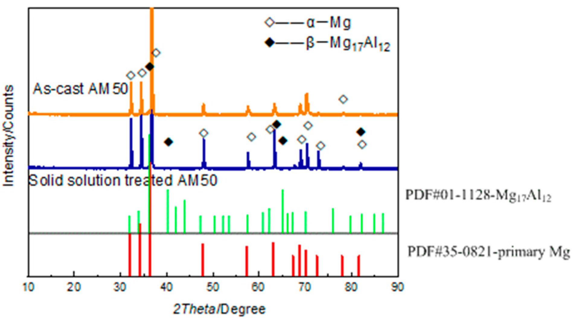
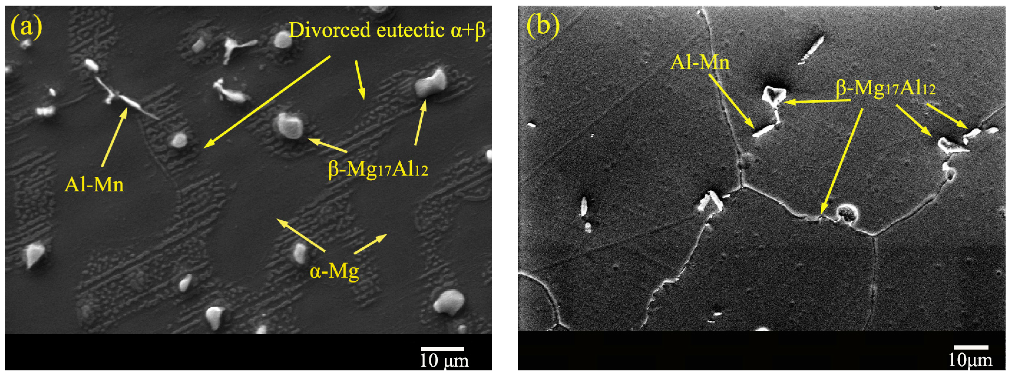
3.1. Microstructure
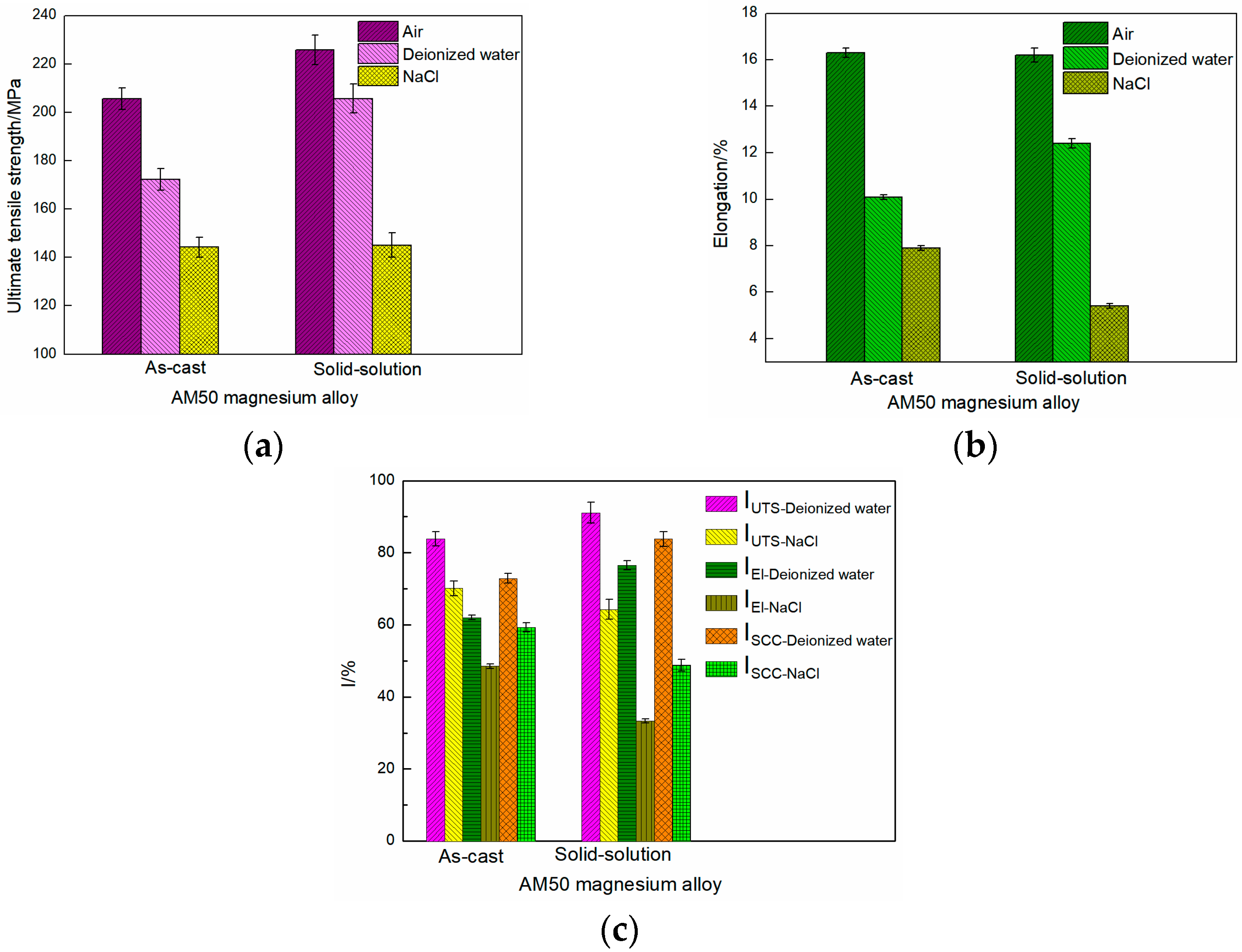
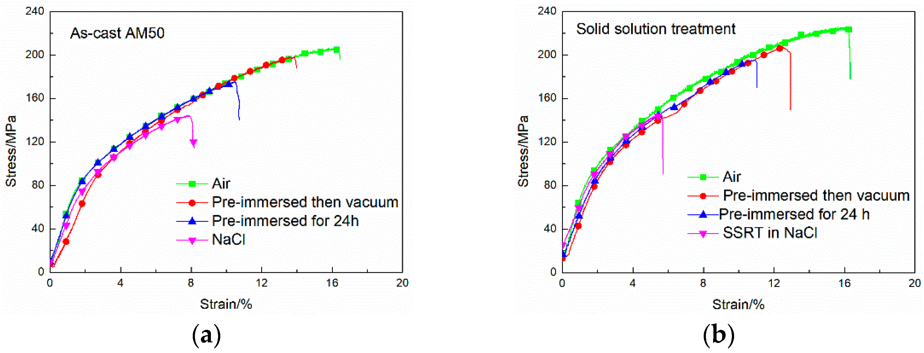
3.2. Corrosion SSRT Test
3.3. Effect of Dehydrogenation on the Stress Corrosion Sensitivity
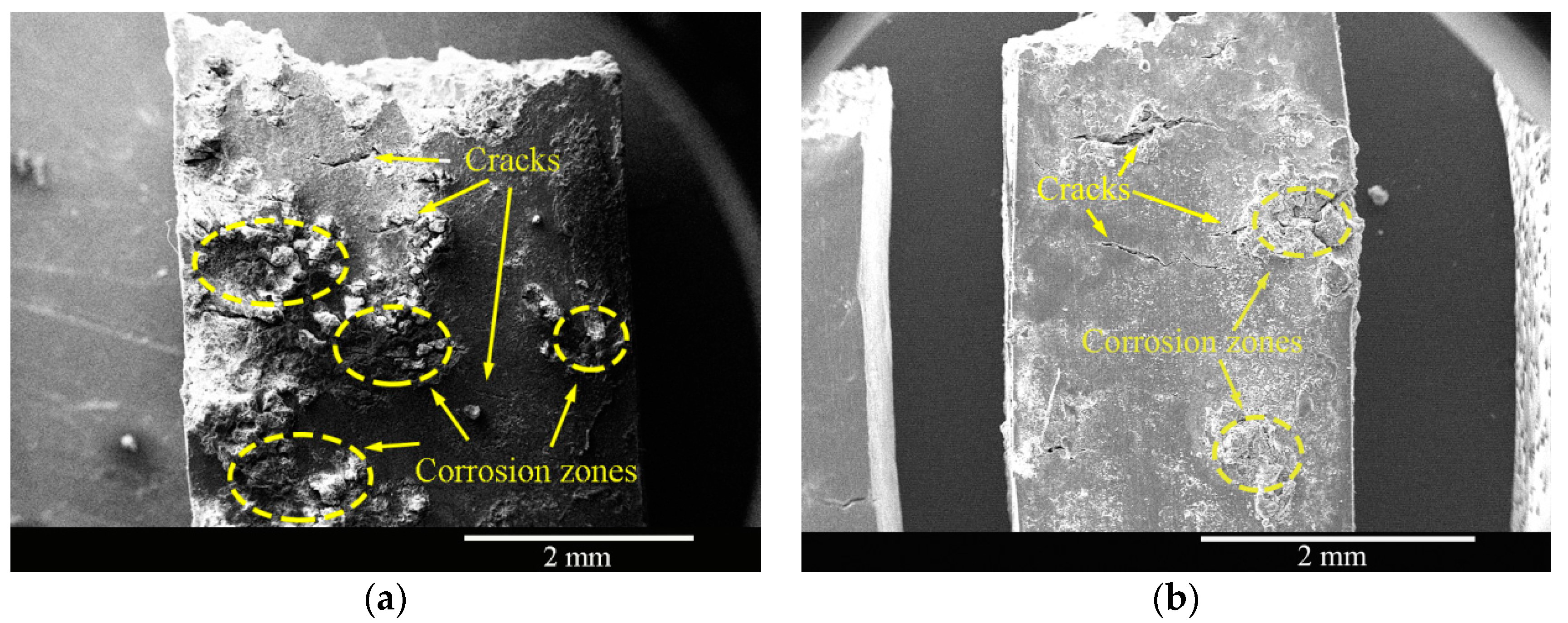
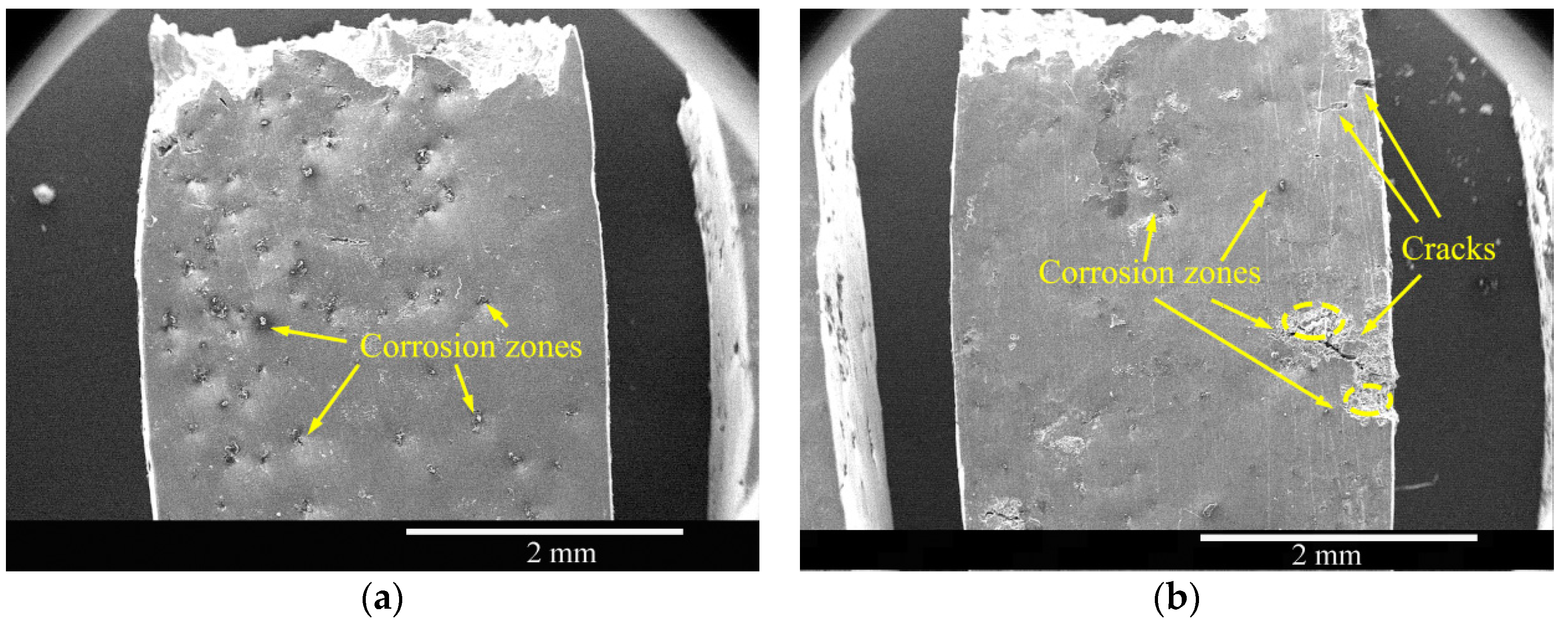
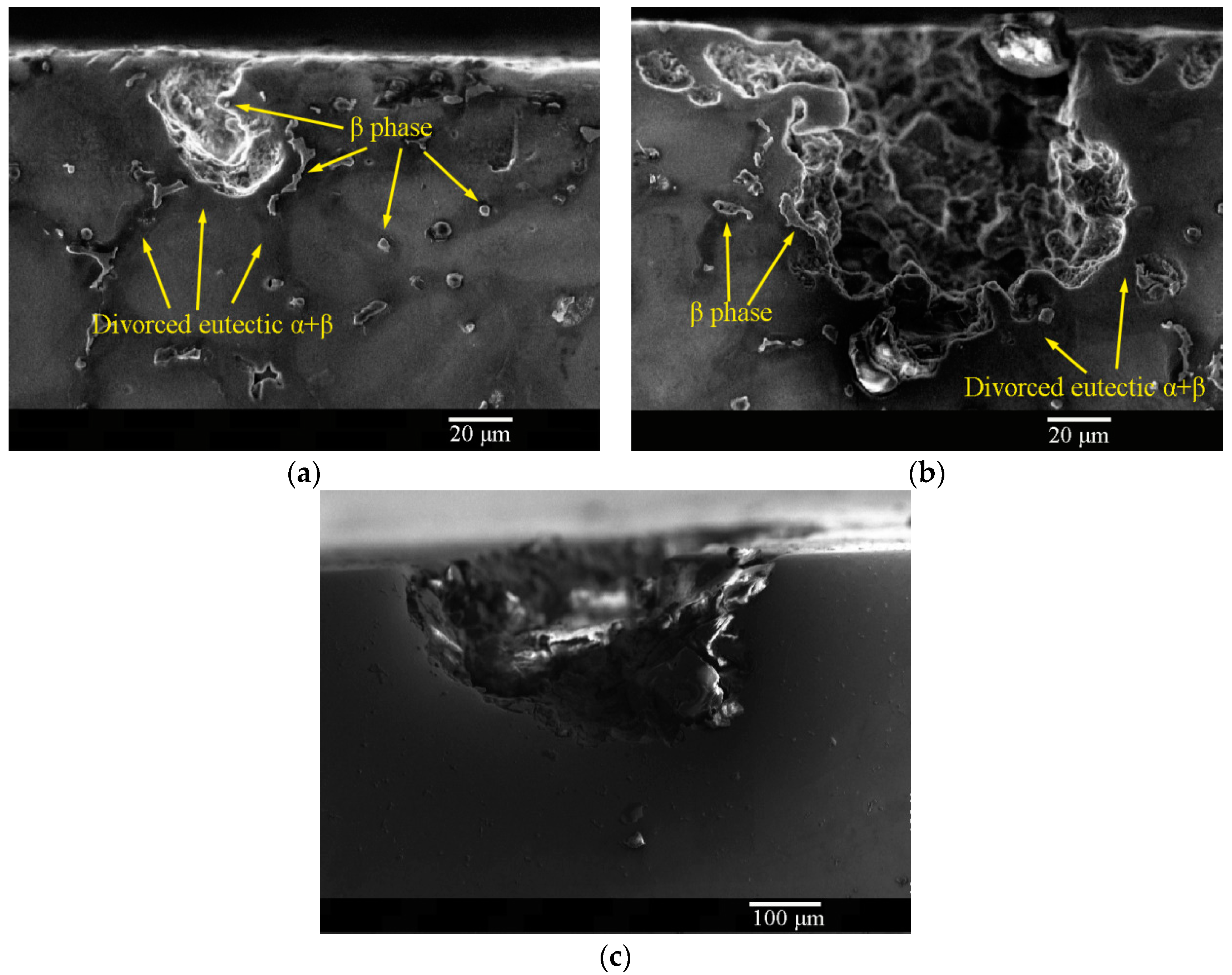
3.4. Corrosion Morphologies of the SSRT Samples
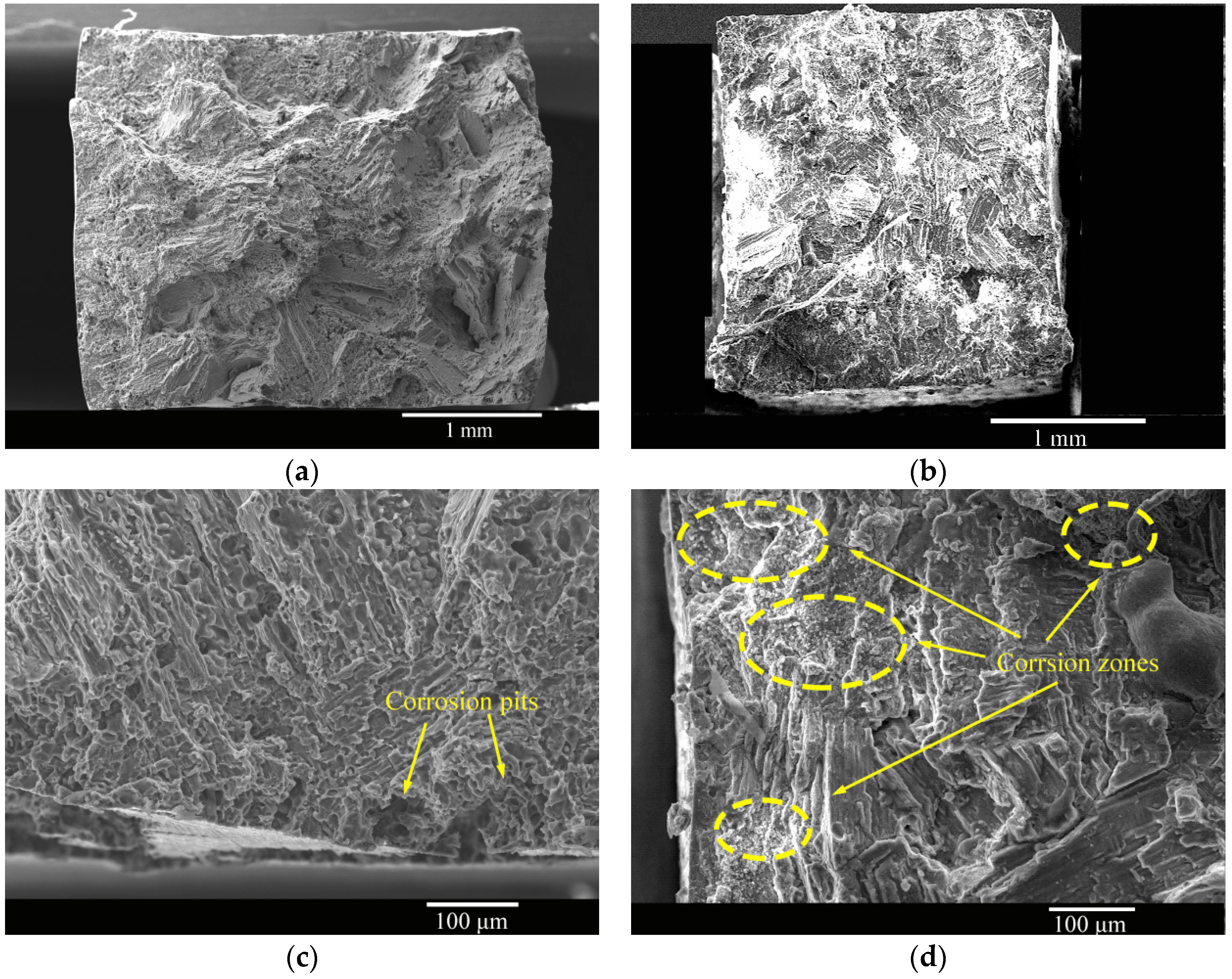
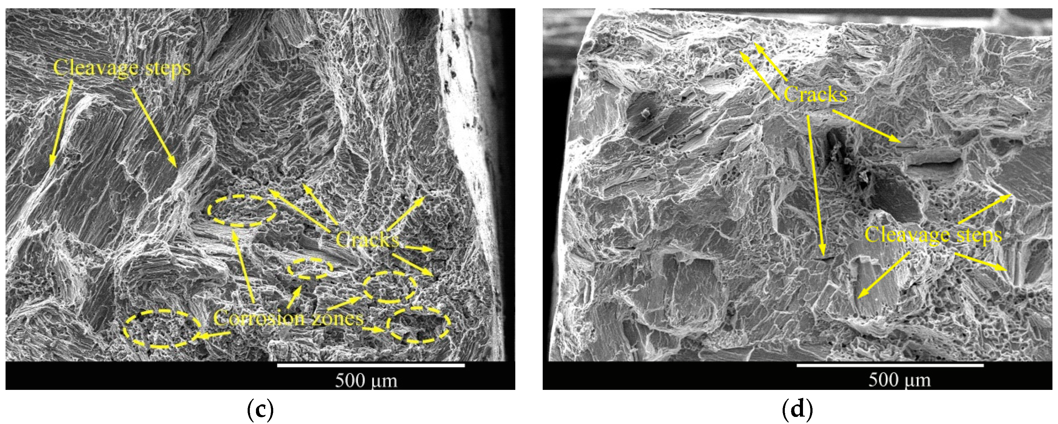
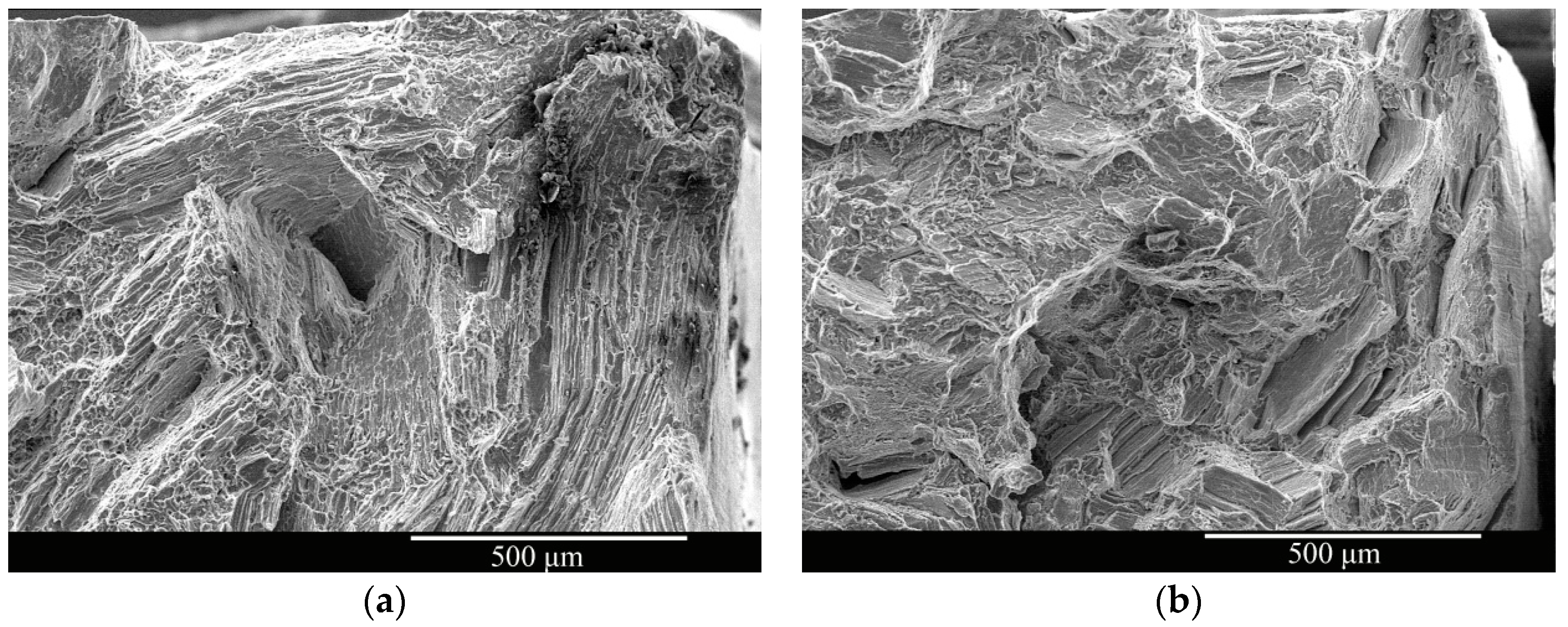
3.5. Fracture Morphologies of the SSRT Samples
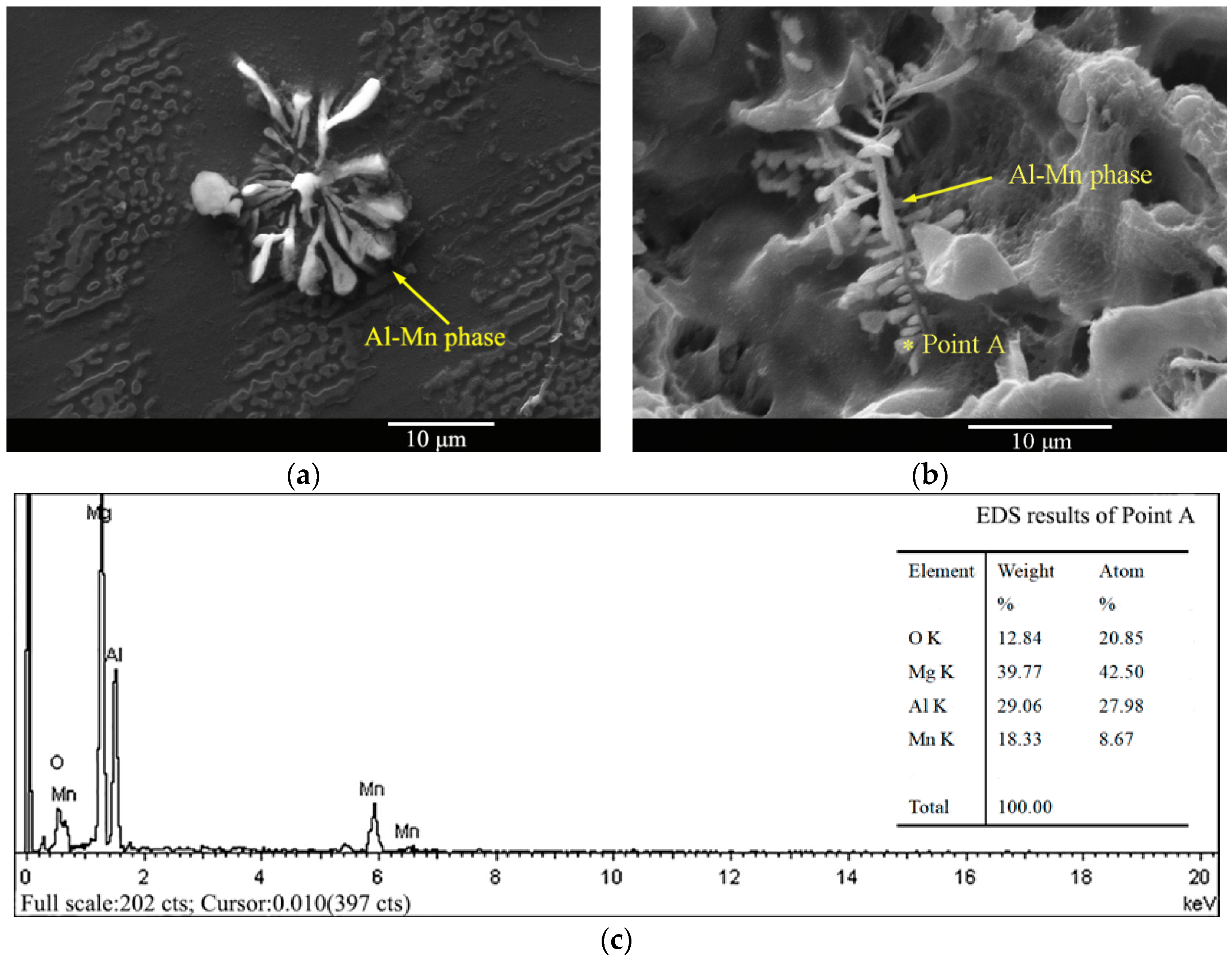
3.6. Al–Mn Phase in the AM50 Magnesium Alloy
4. Discussion
5. Conclusions
- (1)
- The gravity-cast AM50 Mg alloy was composed of α-Mg and β-Mg17Al12 phases. The amount of the β-Mg17Al12 phase significantly decreased after solution treatment, and only a small amount of the β-Mg17Al12 phase existed in the grain boundary. The Al–Mn phase in the structure was fishbone-shaped, and it was most likely Al3Mn;
- (2)
- After solid-solution treatment, the stress corrosion resistance of the AM50 Mg alloy was enhanced in deionized water, but it was weaker in the NaCl solution;
- (3)
- Dehydrogenation experiments showed that the effect of hydrogen on the corrosion process was weakened owing to the decrease of the amount of the β-Mg17Al12 phase after solution treatment. Hydrogen removal experiments showed that, after thermal treatment, the effect of hydrogen after pre-immersion in NaCl solution decreased from 67.4 ± 0.05% to 37.5 ± 0.1% during the slow tensile process;
- (4)
- The effects of hydrogen embrittlement and the anodic dissolution mechanism on the corrosion behavior of the AM50 magnesium alloy under stress were different. In deionized water, the hydrogen embrittlement mechanism played the major role, while the anodic dissolution mechanism played the major role in the presence of Cl− ions.
Author Contributions
Funding
Institutional Review Board Statement
Informed Consent Statement
Data Availability Statement
Acknowledgments
Conflicts of Interest
References
- Yang, M.; Liu, X.; Zhang, Z.; Song, Y.; Bai, L. Effect of adding rare earth elements Er and Gd on the corrosion residual strength of magnesium alloy. Open Phys. 2019, 17, 373–380. [Google Scholar] [CrossRef] [Green Version]
- Yang, M.; Liu, Y.; Liu, J.; Song, Y. Corrosion properties of AM50 magnesium alloy after 1% Er modified. Chin. Rare Earths 2018, 39, 142–148. [Google Scholar] [CrossRef]
- Singh, R.; Venkatesh, V.; Kumar, V. Corrosion: Critical challenge in wider use of magnesium alloys. Metals 2018, 8, 127. [Google Scholar] [CrossRef] [Green Version]
- Song, Y.; Wang, Z.; Liu, Y.; Yang, M.; Qu, Q. Research on stress corrosion behavior of AZ91 magneisum alloy modified by Erbium and Cerium. J. Hunan Univ. 2018, 45, 23–27. [Google Scholar] [CrossRef]
- Song, Y.; Shan, D.; Han, E. Pitting Corrosion of a Rare Earth Mg Alloy GW93. J. Mater. Sci. Technol. 2017, 33, 954–960. [Google Scholar] [CrossRef]
- Esmaily, M.; Svensson, J.; Fajardo, S.; Birbilis, N.; Fankel, G.S.; Virtanen, S.; Arrabal, R.; Tomas, S.; Johansson, L.G. Fundamentals and advances in magnesium alloy corrosion. Prog. Mater. Sci. 2017, 89, 92–193. [Google Scholar] [CrossRef]
- Yang, M.; Zhang, Z.; Liu, Y.; Han, X. Corrosion and mechanical properties of AM50 magnesium alloy after modified by different amounts of rare earth element Gadolinium. Open Phys. 2016, 14, 444–451. [Google Scholar] [CrossRef] [Green Version]
- Istrate, B.; Munteanu, C.; Cimpoesu, R.; Cimpoesu, N.; Popescu, O.D.; Vlad, M.D. Microstructural, Electrochemical and In Vitro Analysis of Mg-0.5Ca-xGd Biodegradable Alloys. Appl. Sci. 2021, 11, 981. [Google Scholar] [CrossRef]
- Zhou, L.; Liu, Z.; Wu, W.; Li, X.; Du, C.; Jiang, B. Stress corrosion cracking behavior of ZK60 magnesium alloy under different conditions. Int. J. Hydrogen. Energ. 2017, 42, 26162–26174. [Google Scholar] [CrossRef]
- Chen, S.; Li, J.; Hu, G.Y.; Chen, K.; Huang, L. Effect of Zn/Mg ratios on SCC, electrochemical corrosion properties and microstructure of Al-Zn-Mg alloy. J. Alloy Compd. 2018, 757, 259–264. [Google Scholar] [CrossRef]
- Zhang, X.; Zhang, K. Research progress on corrosion behavior and mechanism of magnesium alloys. Corro. Sci. Protec. Technol. 2015, 27, 78–84. [Google Scholar] [CrossRef]
- Winzer, N.; Atrens, A.; Dietzel, W.; Song, G.; Kainer, K.U. Evaluation of the delayed hydride cracking mechanism for transgranular stress corrosion cracking of magnesium alloys. Mater. Sci. Eng. A 2007, 466, 18–31. [Google Scholar] [CrossRef] [Green Version]
- Chen, J.; Wang, J.; Han, E.; Dong, J.; Ke, W. States and transport of hydrogen in the corrosion process of an AZ91 magnesium alloy in aqueous solution. Corro. Sci. 2008, 50, 1292–1305. [Google Scholar] [CrossRef]
- Winzer, N.; Atrens, A.; Dietzel, W.; Song, G.; Kainer, K.U. Characterisation of stress corrosion cracking ( SCC ) of Mg-Al alloys. Mater. Sci. Eng. A 2008, 48, 339–351. [Google Scholar] [CrossRef]
- Atrens, A.; Winzer, N.; Dietzel, W. Stress Corrosion Cracking of Magnesium Alloys. Adv. Eng. Mater. 2011, 13, 341–380. [Google Scholar] [CrossRef] [Green Version]
- Winzer, N.; Atrens, A.; Dietzel WSong, G.; Kainer, K.U. Fractography of Stress Corrosion Cracking of Mg-Al Alloys. Metall. Mater. Trans. A 2008, 39, 1157–1173. [Google Scholar] [CrossRef] [Green Version]
- Song, R.G.; Blawert, C.; Dietzel, W.; Atrens, A. A study on stress corrosion cracking and hydrogen embrittlement of AZ31 magnesium alloy. Mater. Sci. Eng. A 2005, 399, 308–317. [Google Scholar] [CrossRef]
- Nan, Z.Y.; Ishihara, S.; Goshima, T. Corrosion fatigue behavior of extruded magnesium alloy AZ31in sodium chloride solution. Int. J. Fatigue 2008, 30, 1181–1188. [Google Scholar] [CrossRef]
- Qi, F.; Zhang, X.; Wu, G.; Liu, W.; Wen, L.; Xie, H.; Xu, S.; Tong, X. Effect of heat treatment on the stress corrosion cracking behavior of cast Mg-3Nd-3Gd-0.2Zn-0.5Zr alloy in a 3.5 wt% NaCl salt spray environment. Mater. Charact. 2022, 183, 111630. [Google Scholar] [CrossRef]
- Tuchscheerer, F.; Krüger, L. Hydrogen-induced embrittlement of fine-grained twinroll cast AZ31 in distilled water and NaCl solutions. J. Mater. Sci. 2015, 50, 5104–5113. [Google Scholar] [CrossRef]
- Merson, E.; Poluyanov, V.; Myagkikh, P.; Merson, D.; Vinogradov, A. On the role of pre-exposure time and corrosion products in stress-corrosion cracking of ZK60 and AZ31 magnesium alloys. Mater. Sci. Eng. A 2021, 806, 140876. [Google Scholar] [CrossRef]
- Merson, E.; Poluyanov, V.; Myagkikh, P.; Merson, D.; Vinogradov, A. Inhibiting stress corrosion cracking by removing corrosion products from the Mg-Zn-Zr alloy pre-exposed to corrosion solutions. Acta Mater. 2021, 205, 116570. [Google Scholar] [CrossRef]
- Pan, F.; Feng, Z.; Zhang, X.; Tang, A. The Types and Distribution Characterization of Al-Mn Phases in the AZ61 Magnesium Alloy. Procedia Eng. 2012, 27, 833–839. [Google Scholar] [CrossRef] [Green Version]
- Merson, E.; Poluyanov, V.; Myagkikh, P.; Merson, D.; Vinogradov, A. Effect of Air Storage on Stress Corrosion Cracking of ZK60 Alloy Induced by Preliminary Immersion in NaCl-Based Corrosion Solution. Materials 2022, 15, 7862. [Google Scholar] [CrossRef] [PubMed]
- Kannan, B.M.; Diezel, W.; Raman, S.R.K.; Lyon, P. Hydrogen-induced-cracking in magnesium alloy under cathodic polarization. Scripta. Mater. 2007, 57, 579–581. [Google Scholar] [CrossRef]
- Yang, M.; Liu, Y.; Liu, J.; Song, Y. Effect of T6 heat treatment on corrosion resistance and mechanical properties of AM50 magnesium alloy. Mater. Res. Innov. 2015, 19, 259–264. [Google Scholar] [CrossRef]
- Wang, B.; Xu, D.; Wang, S.; Sheng, L.; Zeng, R.; Han, E. Influence of solution treatment on the corrosion fatigue behavior of an as-forged Mg-Zn-Y-Zr alloy. Inter. J. Fatigue 2019, 120, 46–55. [Google Scholar] [CrossRef]
- Song, Y.; Fu, H.; Wang, Z.; Yang, P. Stress corrosion cracking of magnesium alloys: Mechanism, influencing factors, and prevention technology. Mater. Rep. 2019, 33, 834–840. [Google Scholar] [CrossRef]
- Song, Y.; Wang, Z.; Liu, Y.; Yang, M.; Qu, Q. Influence of erbium, cerium on the stress corrosion cracking behavior of AZ91 alloy in humid atmosphere. Adv. Eng. Mater. 2017, 19, 1700021. [Google Scholar] [CrossRef]
- Zeng, R.; Zhang, J.; Huang, W.; Dietzel, W.; Kainer, K.U.; Blawert, C.; Ke, W. Review of studies on corrosion of magnesium alloys. Trans. Nonferr. Metal. Soc. 2006, 16, 763–771. [Google Scholar] [CrossRef]
- Chen, J.; Dong, J.; Wang, J.; Han, E.; Ke, W. Effect of magnesium hydride on the corrosion behavior of an AZ91 magnesium alloy in sodium chloride solution. Corro. Sci. 2008, 50, 3610–3614. [Google Scholar] [CrossRef]
- Zeng, R.; Kainer, K.U.; Blawert, C.; Diezel, W. Corrosion of an extruded magnesium alloy ZK60 component—The role of microstructural features. J. Alloy Compd. 2011, 509, 4462–4469. [Google Scholar] [CrossRef]
- Song, G.; Atrens, A. Understanding magnesium corrosion-a framework for improved alloy performance. Adv. Eng. Mater. 2010, 5, 837–858. [Google Scholar] [CrossRef]
- Song, G.; Bowles, A.L.; Stjohn, D.H. Corrosion resistance of aged die cast magnesium alloy AZ91D. Mater. Sci. Eng. A 2004, 366, 74–86. [Google Scholar] [CrossRef]


| Al | Mn | Zn | Si | Cu | Ni | Mg |
|---|---|---|---|---|---|---|
| 4.8687 | 0.2823 | 0.1232 | 0.0161 | 0.0015 | 0.0008 | Bal. |
| Alloy | Method | Analysis | ||||||
|---|---|---|---|---|---|---|---|---|
| Data | Air | Immersion | Vacuum Dehydrogen | Total Effect | Hydrogen Effect | IH (%) | IH,total (%) | |
| As-cast | UTS (MPa) | 205.6 | 174.6 | 198.0 | −31.0 | +23.4 | 75.5 | 67.4 ± 0.05 |
| UTS-Error | ±6.0 | ±4.2 | ±4.0 | ±1.8 | ±0.2 | ±0.1 | ||
| EL (%) | 16.3 | 10.4 | 13.9 | −5.9 | +3.5 | 59.3 | ||
| El-Error | ±0.2 | ±0.1 | ±0.1 | ±0.1 | 0 | 0 | ||
| Solid-solution | UTS (MPa) | 223.9 | 194.2 | 207.5 | −29.7 | +13.3 | 44.8 | 37.5 ± 0.1 |
| UTS-Error | ±6.1 | ±4.4 | ±4.8 | ±1.7 | ±0.4 | ±0.2 | ||
| EL (%) | 16.2 | 10.9 | 12.5 | −5.3 | +1.6 | 30.2 | ||
| El-Error | ±0.3 | ±0.2 | ±0.2 | ±0.1 | 0 | 0 | ||
Disclaimer/Publisher’s Note: The statements, opinions and data contained in all publications are solely those of the individual author(s) and contributor(s) and not of MDPI and/or the editor(s). MDPI and/or the editor(s) disclaim responsibility for any injury to people or property resulting from any ideas, methods, instructions or products referred to in the content. |
© 2023 by the authors. Licensee MDPI, Basel, Switzerland. This article is an open access article distributed under the terms and conditions of the Creative Commons Attribution (CC BY) license (https://creativecommons.org/licenses/by/4.0/).
Share and Cite
Yang, M.; Liu, X.; Xing, L.; Chen, Z. Corrosion and Mechanical Behavior of the As-Cast and Solid-Solution-Treated AM50 Magnesium Alloy in Different Media. Materials 2023, 16, 2406. https://doi.org/10.3390/ma16062406
Yang M, Liu X, Xing L, Chen Z. Corrosion and Mechanical Behavior of the As-Cast and Solid-Solution-Treated AM50 Magnesium Alloy in Different Media. Materials. 2023; 16(6):2406. https://doi.org/10.3390/ma16062406
Chicago/Turabian StyleYang, Miao, Xiaobo Liu, Liyun Xing, and Zhaoyu Chen. 2023. "Corrosion and Mechanical Behavior of the As-Cast and Solid-Solution-Treated AM50 Magnesium Alloy in Different Media" Materials 16, no. 6: 2406. https://doi.org/10.3390/ma16062406