
A Novel Approach for Powder Bed Fusion of Ceramics Using Two Laser Systems
 , , ,
, , ,  and
and
Abstract
:1. Introduction
2. Materials and Methods
2.1. Numerical Method
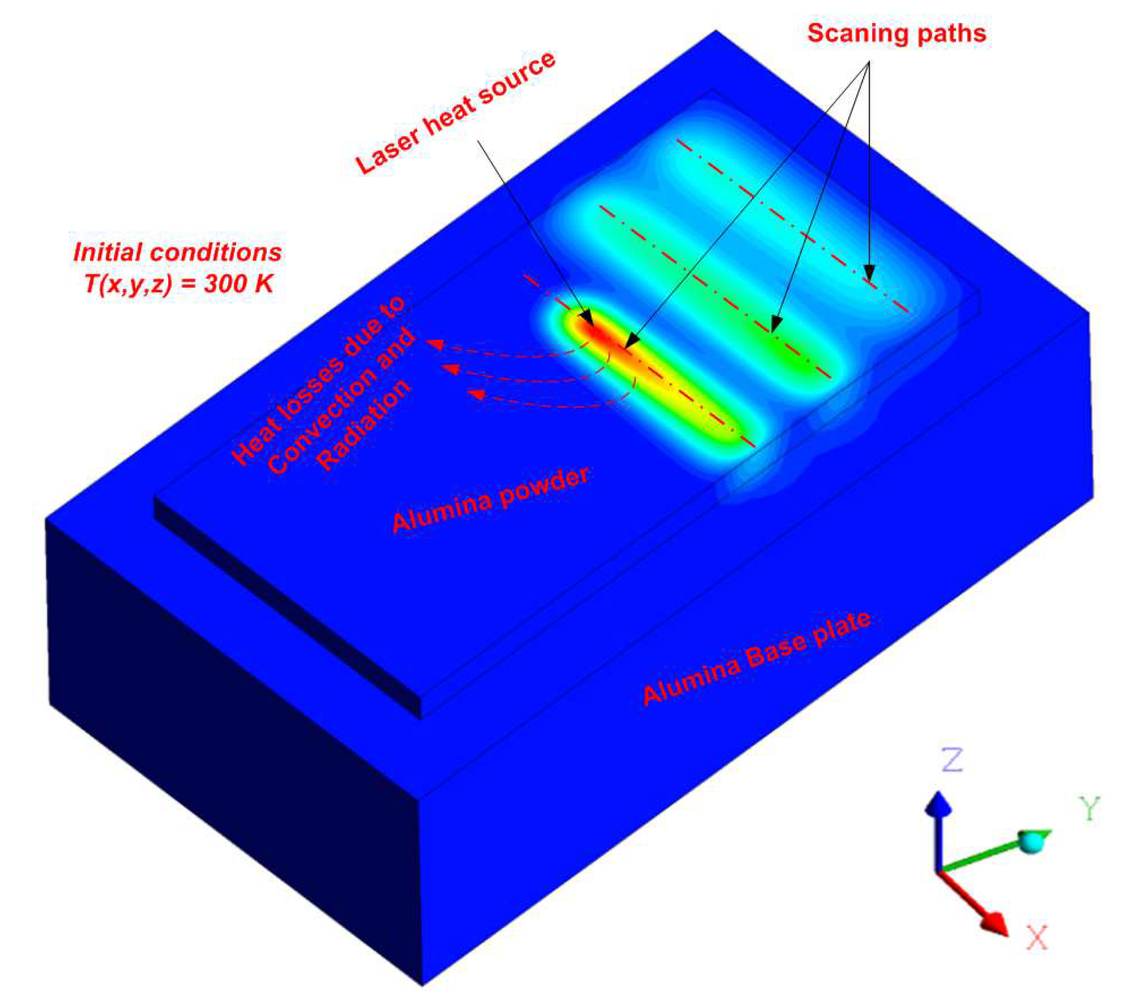
2.1.1. Numerical Model Development
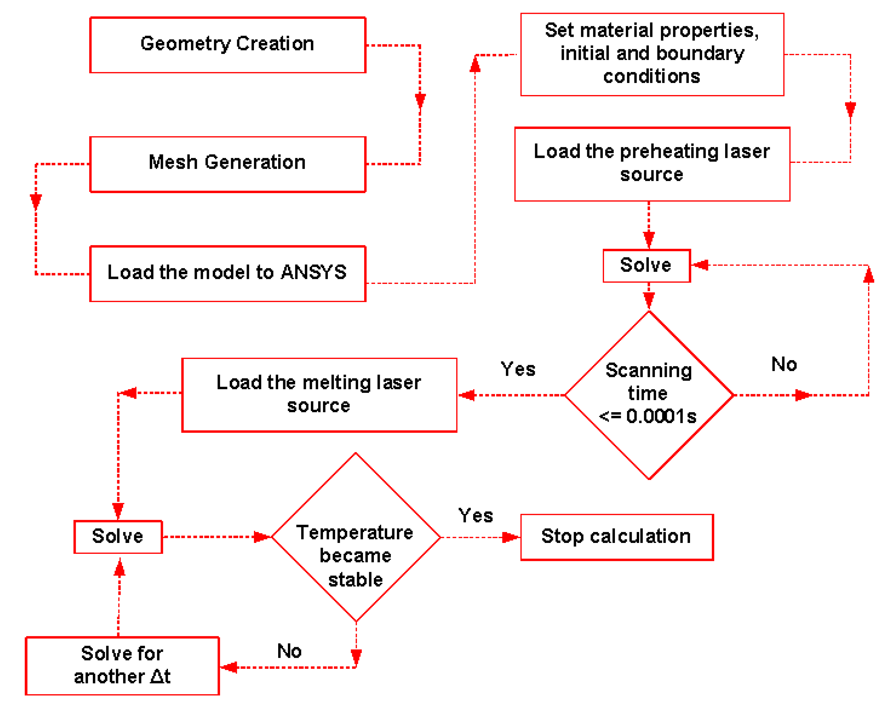
2.1.2. Numerical Solution
2.2. Experimental Method
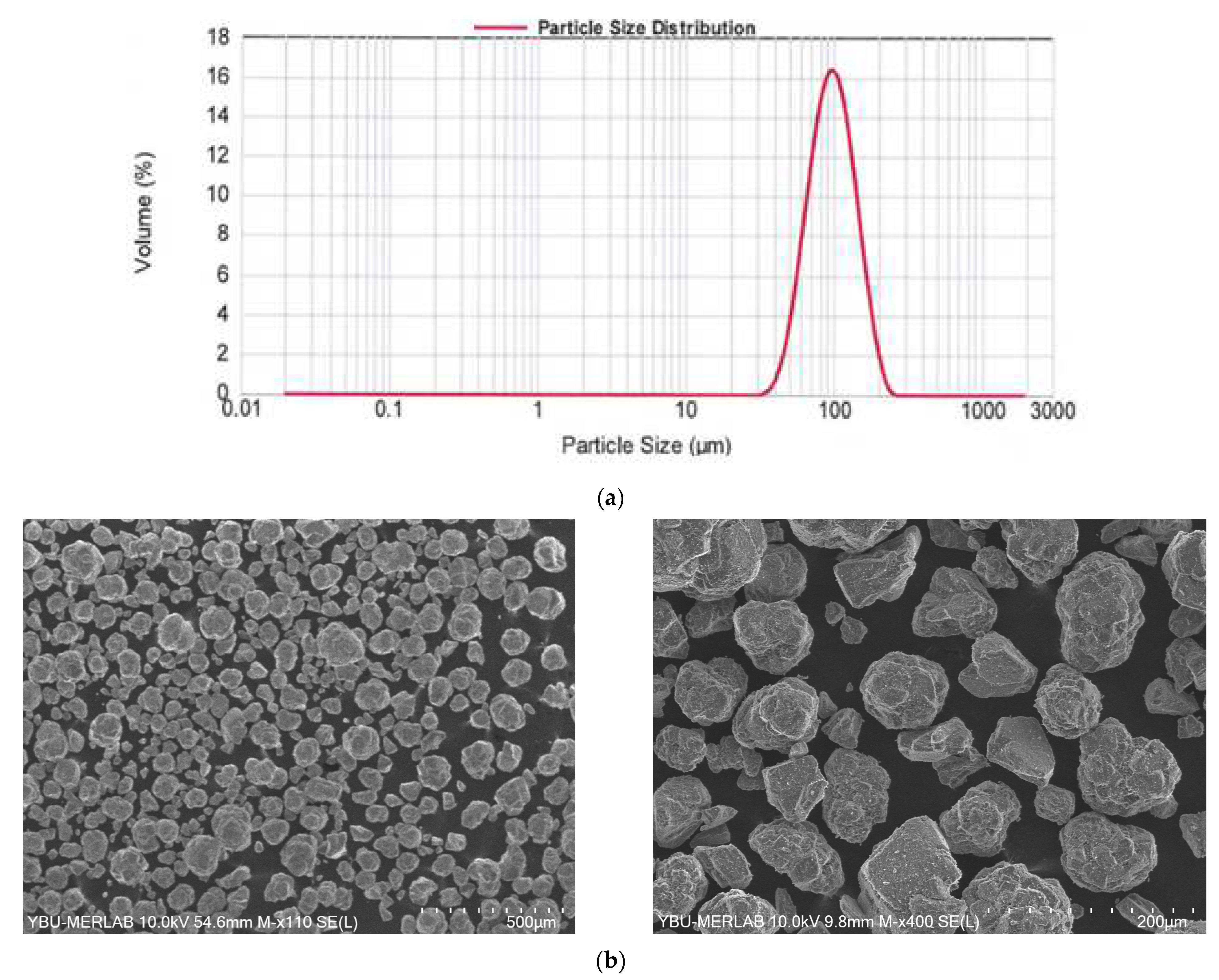
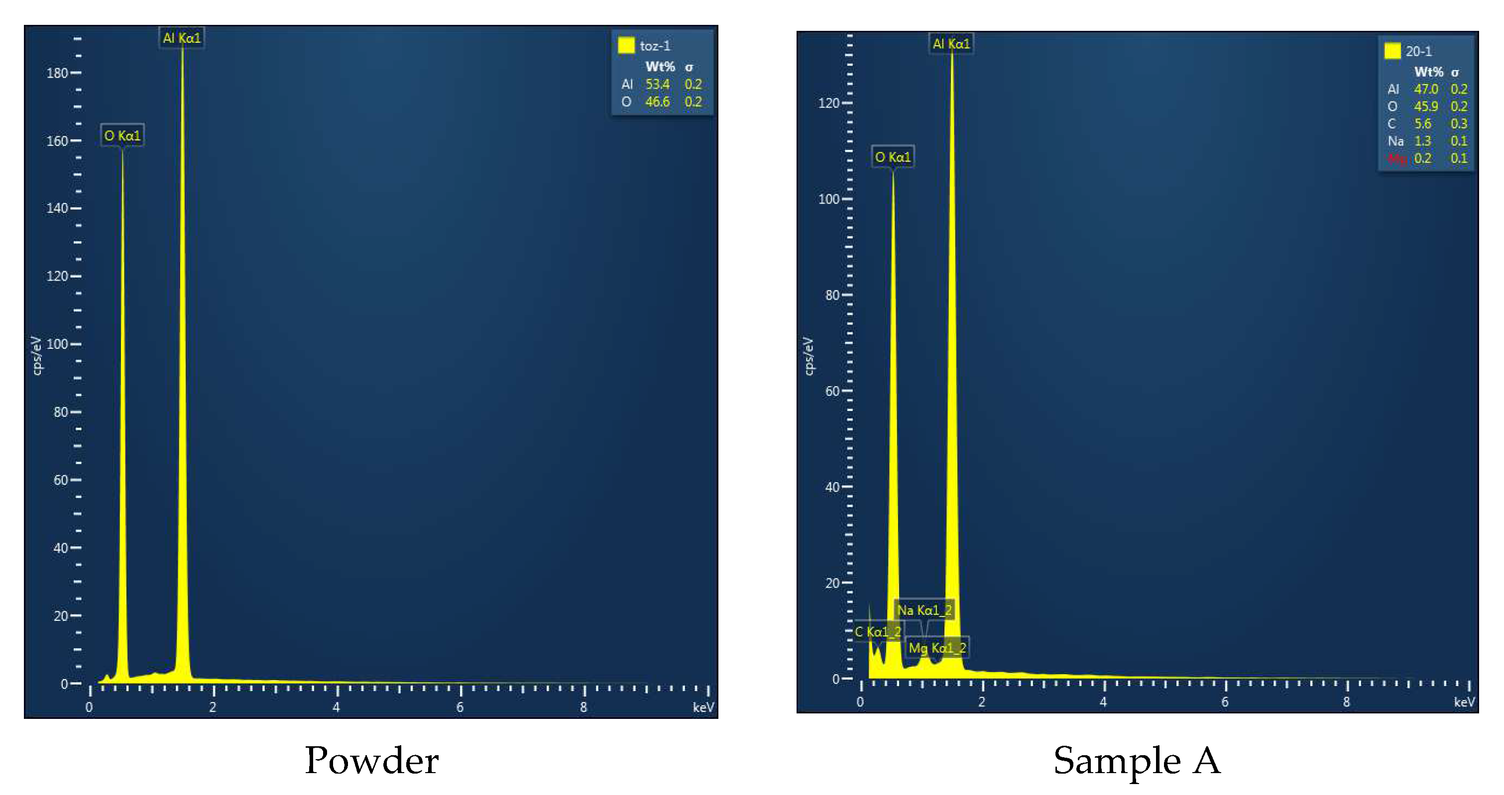
2.2.1. Feedstock Material
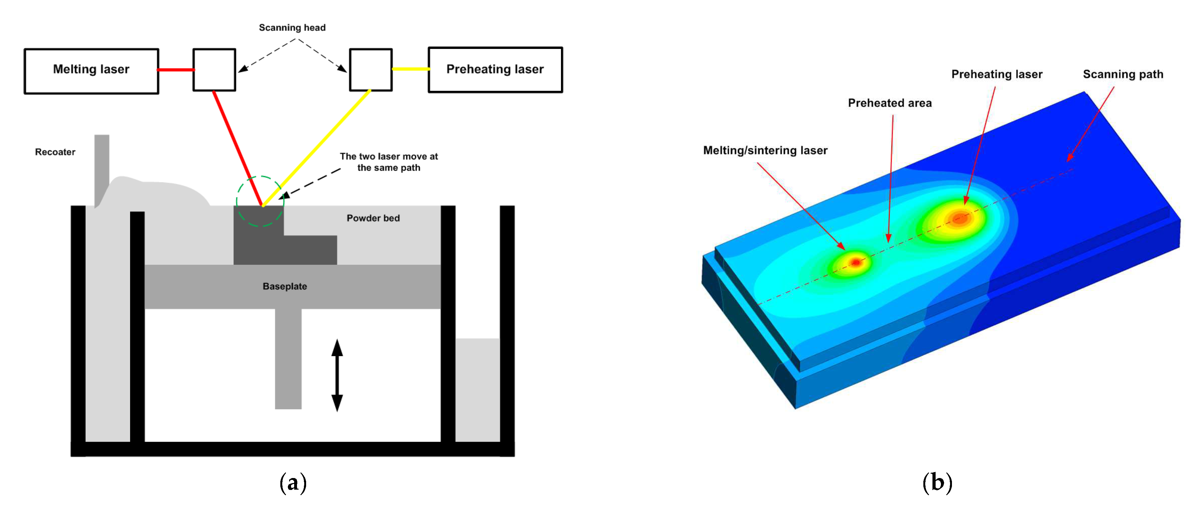
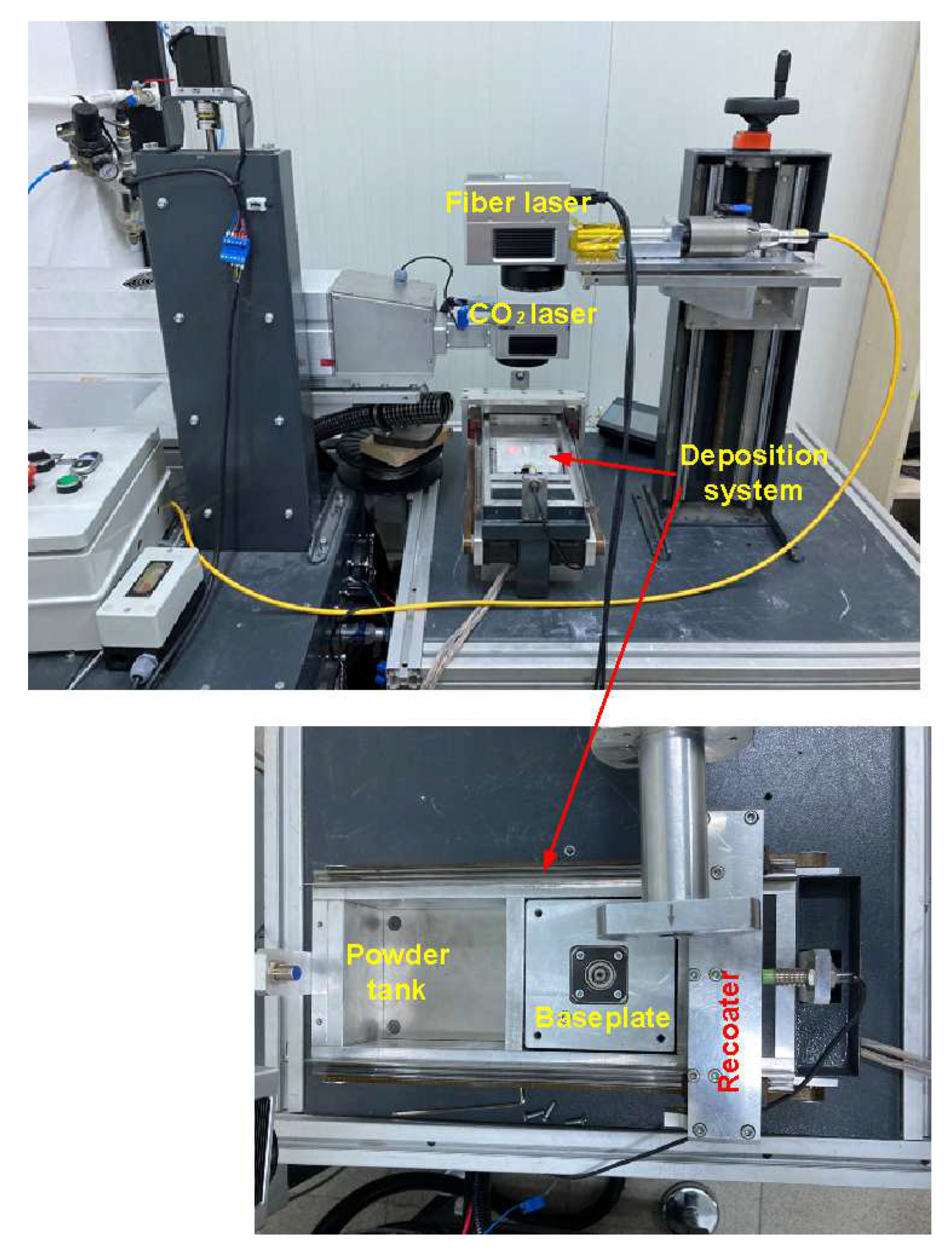
2.2.2. The Developed Experimental Setup
2.2.3. Sample Preparation and Characterisation Methods
3. Results
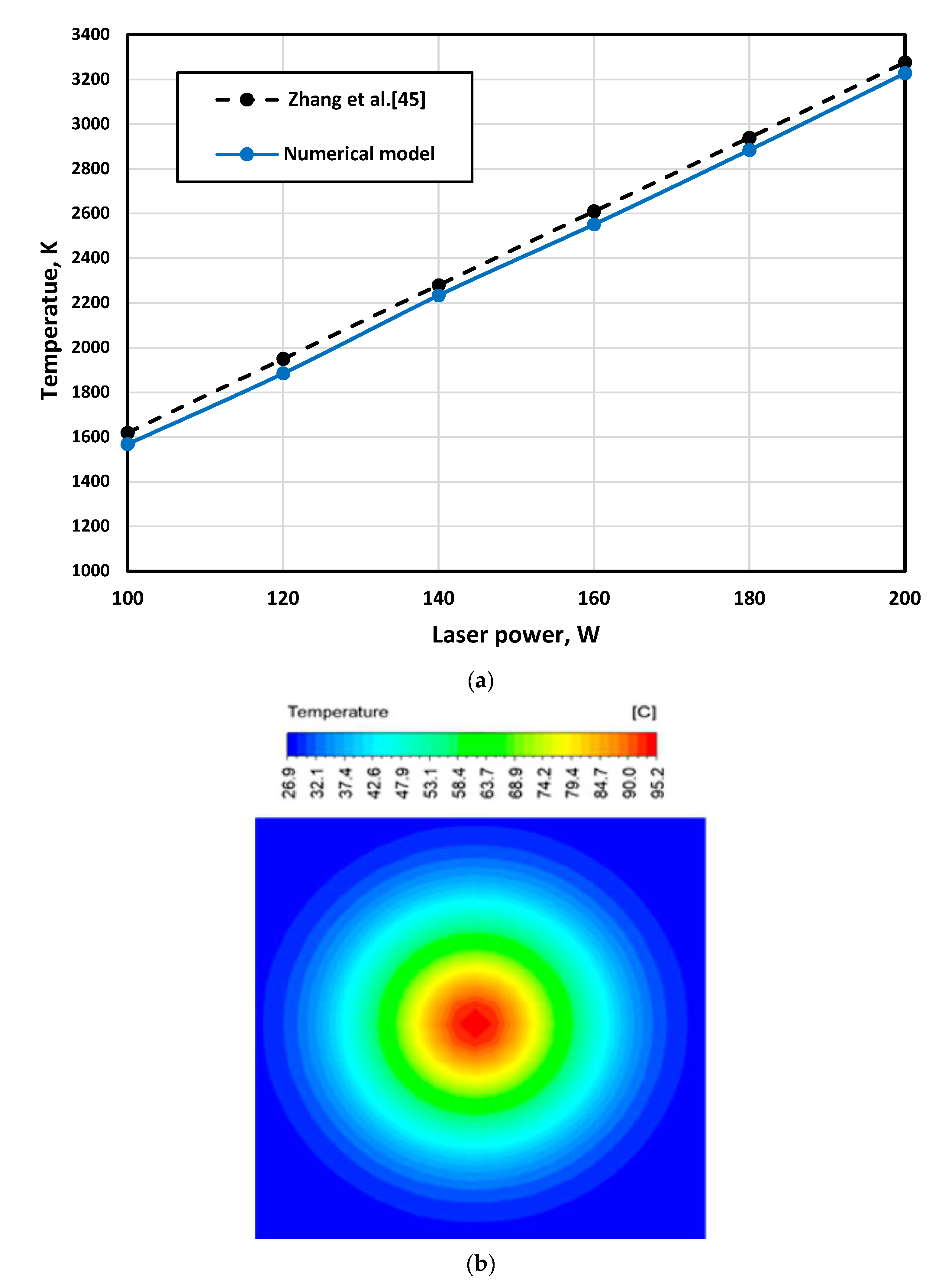
3.1. Numerical Model Validation
3.2. Numerical Results
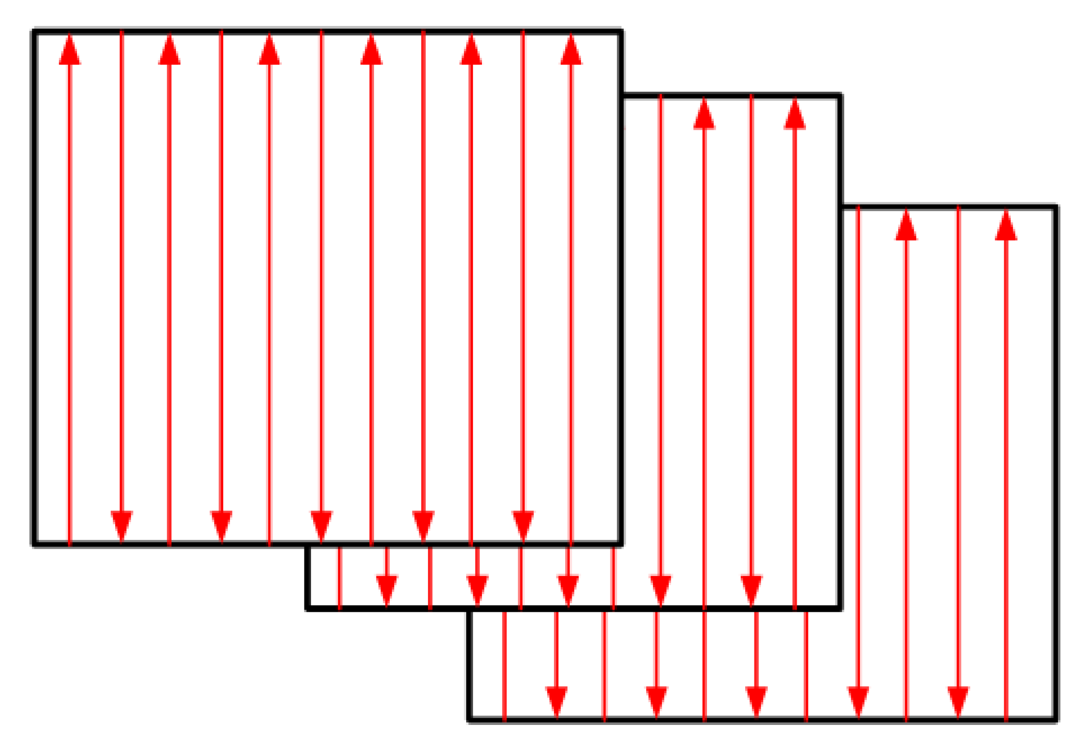
3.2.1. Laser Power and Scanning Speed
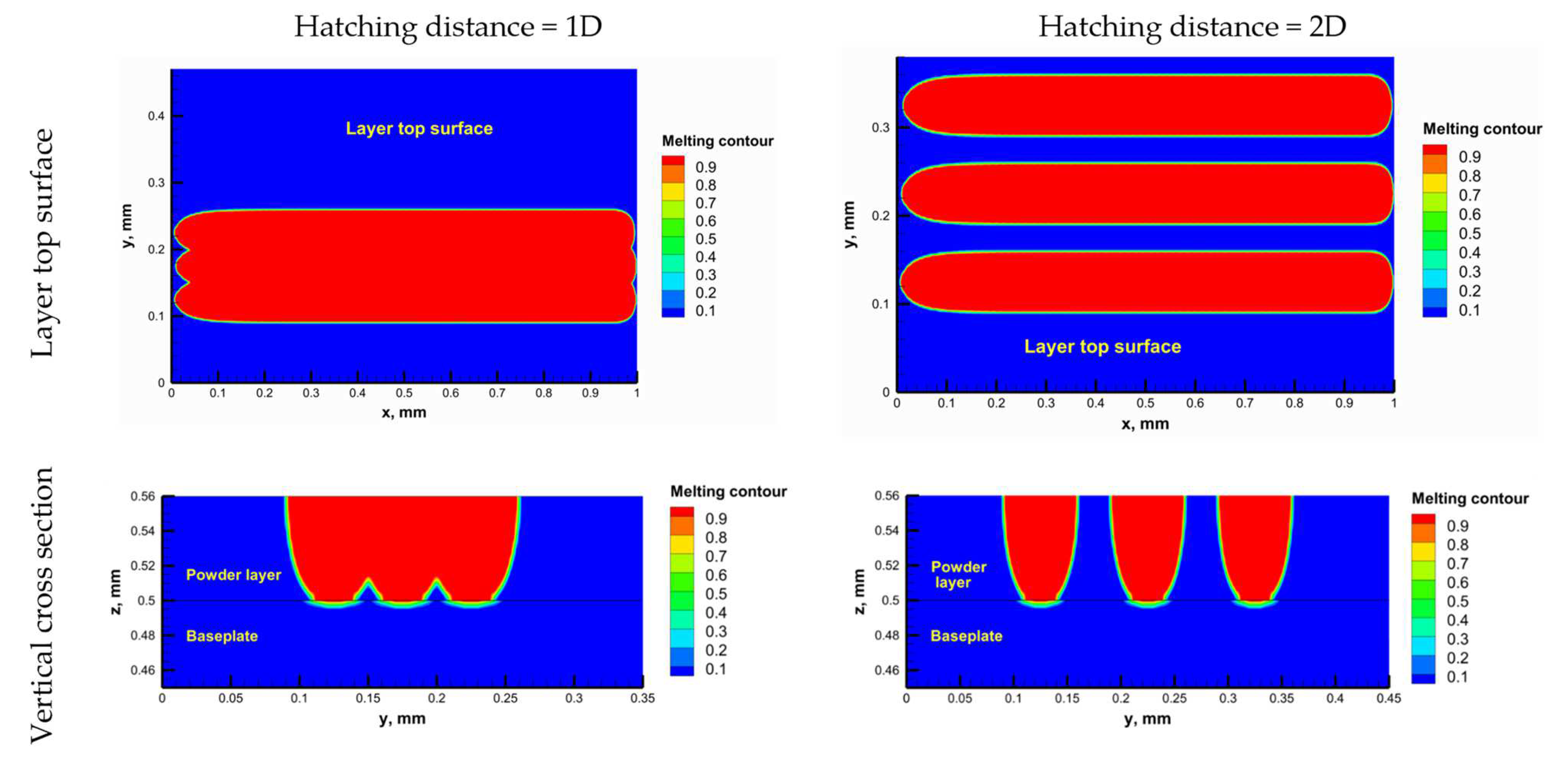
3.2.2. Hatching Distance
3.3. Experimental Results
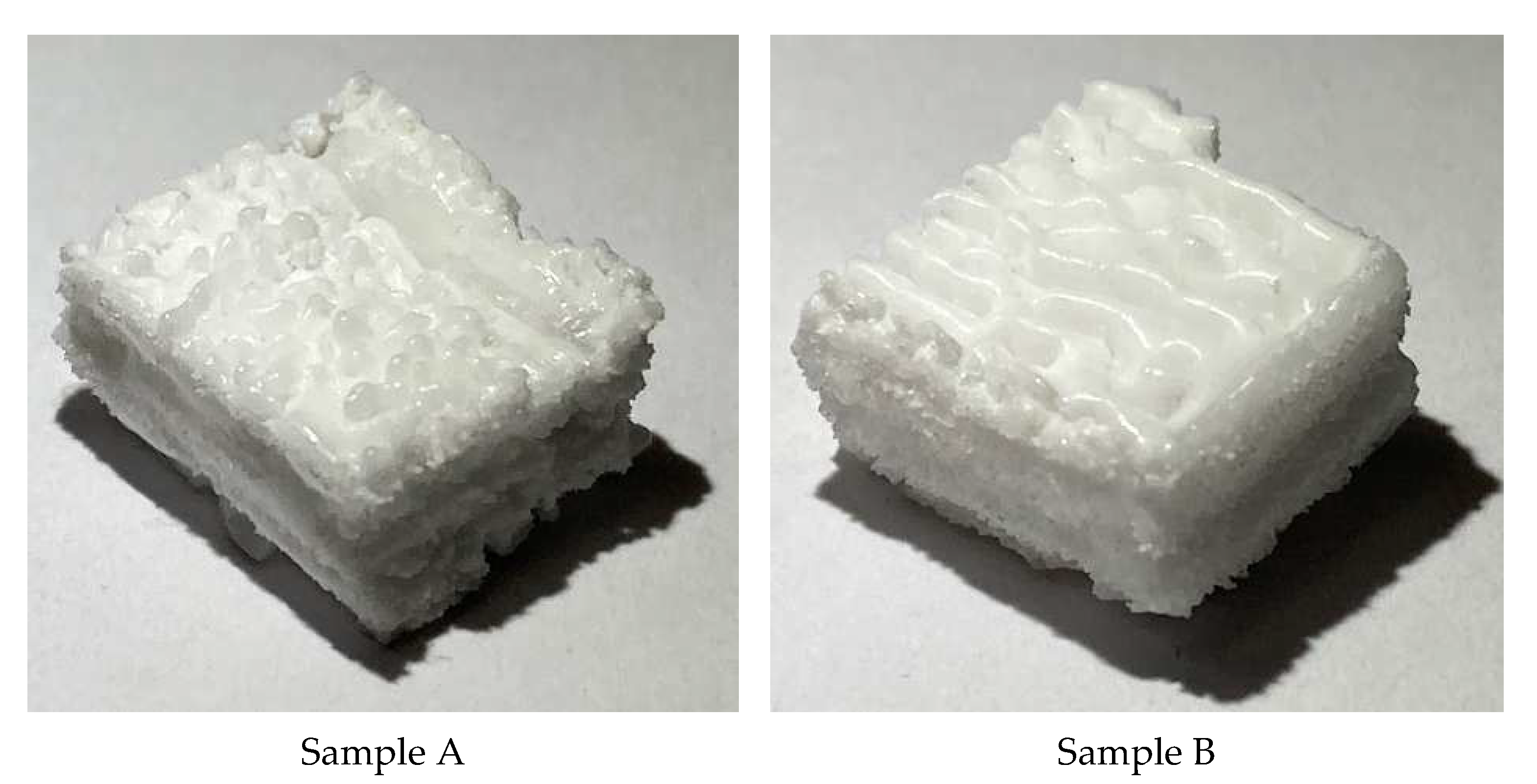
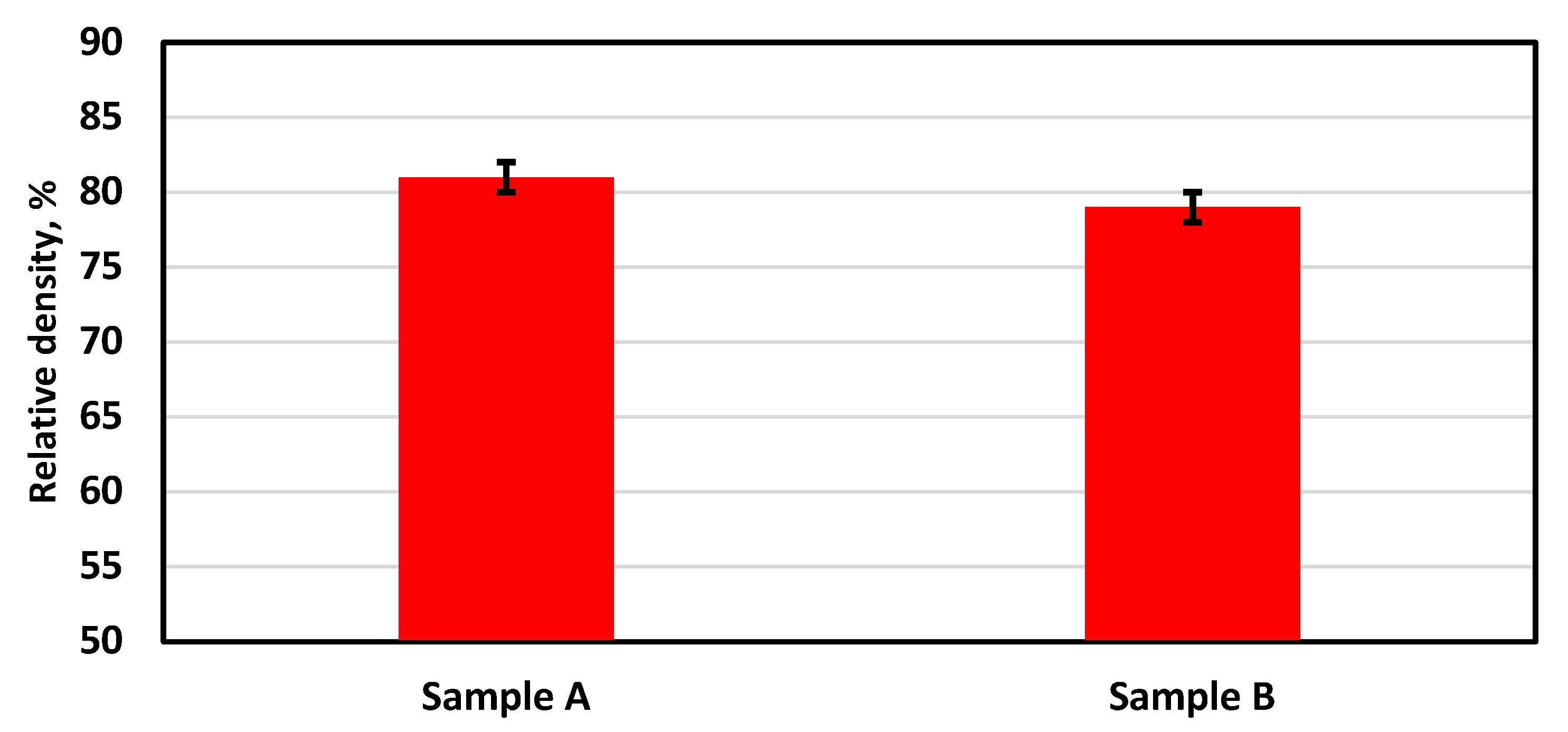
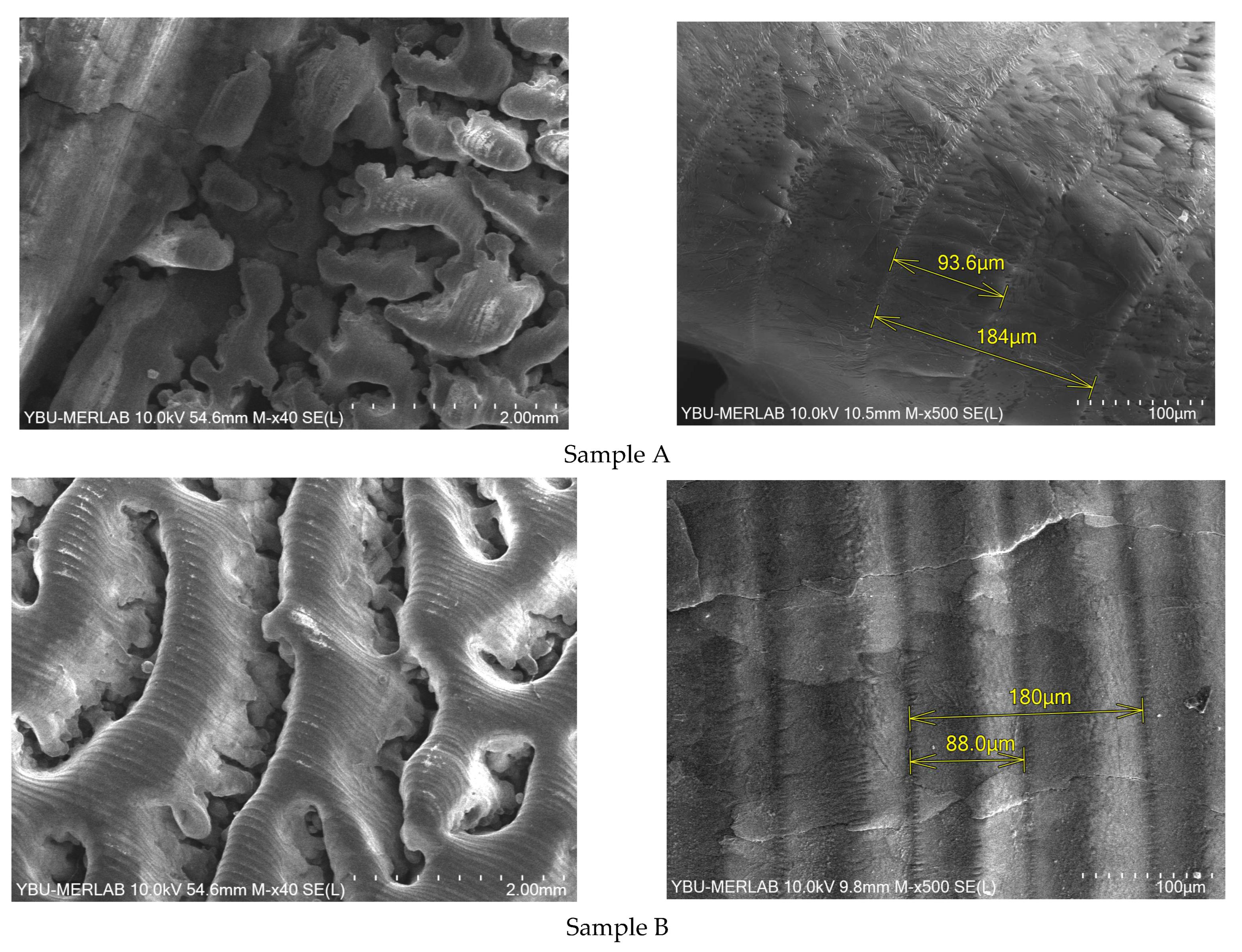
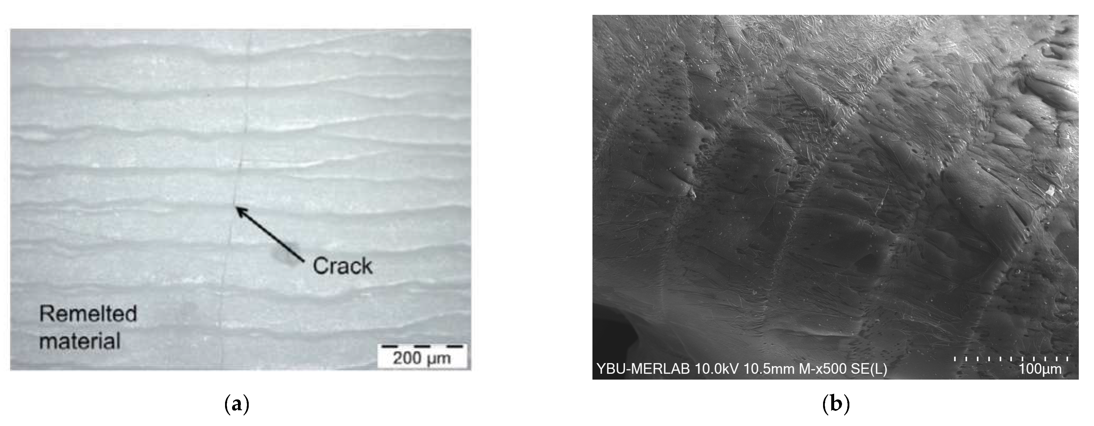
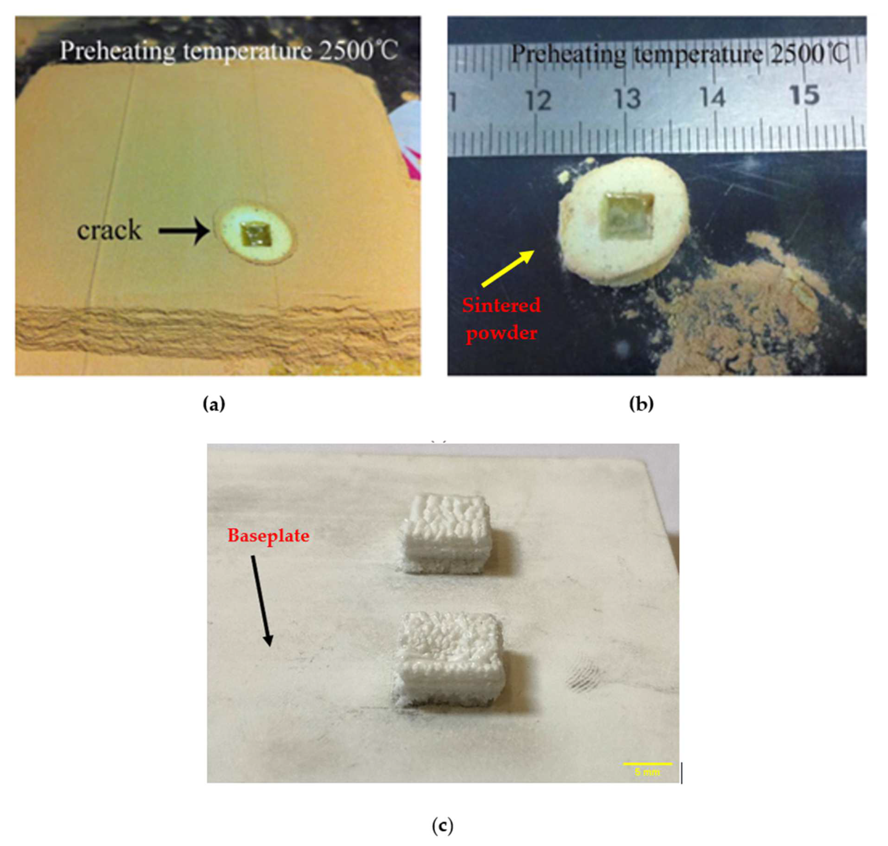
3.3.1. PBF of Alumina Samples
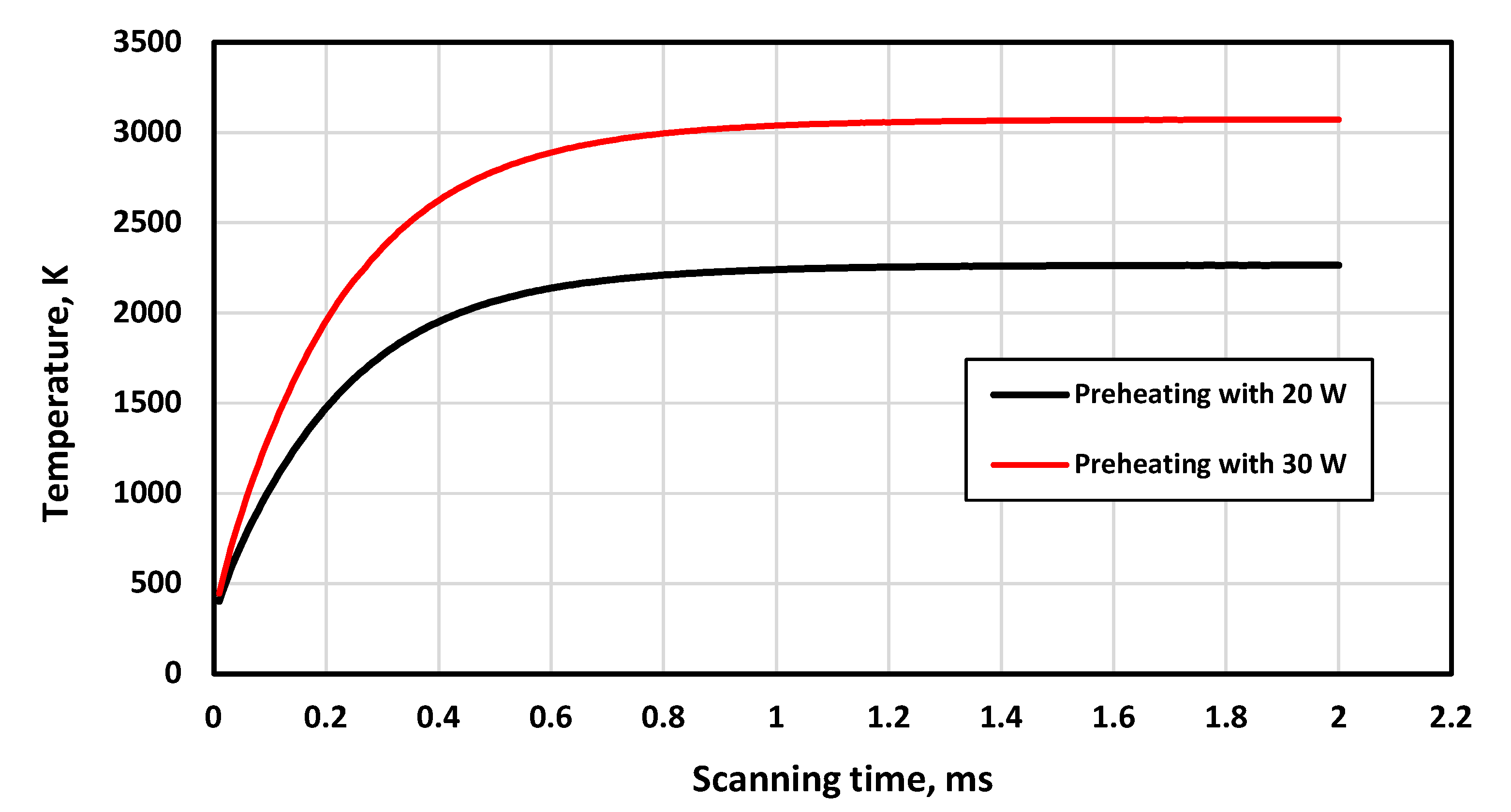
3.3.2. Evaluation of the Developed Preheating System
4. Conclusions
Author Contributions
Funding
Institutional Review Board Statement
Informed Consent Statement
Data Availability Statement
Conflicts of Interest
References
- Auerkari, P. Mechanical and Physical Properties of Engineering Alumina Ceramics; Technical Research Centre of Finland: Espoo, Finland, 1996; Volume 23. [Google Scholar]
- Bian, H.; Song, X.; Hu, S.; Lei, Y.; Jiao, Y.; Duan, S.; Feng, J.; Long, W. Microstructure Evolution and Mechanical Properties of Titanium/Alumina Brazed Joints for Medical Implants. Metals 2019, 9, 644. [Google Scholar] [CrossRef] [Green Version]
- Kim, J.-H.; Yoo, S.-J.; Kwak, D.-H.; Jung, H.-J.; Kim, T.-Y.; Park, K.-H.; Lee, J.-W. Characterisation and application of electrospun alumina nanofibers. Nanoscale. Res. Lett. 2014, 9, 44. [Google Scholar] [CrossRef] [Green Version]
- Hirashima, H.; Kojima, C.; Imai, H. Application of alumina aerogels as catalysts. J. Sol.-Gel. Sci. Technol. 1997, 8, 843–846. [Google Scholar] [CrossRef]
- Fu, L.; Huang, A.; Gu, H.; Ni, H. Properties and microstructures of lightweight alumina containing different types of nano-alumina. Ceram. Int. 2018, 44, 17885–17894. [Google Scholar] [CrossRef]
- Tarì, G.; Ferreira, J.M.F.; Lyckfeldt, O. Infuence of the Stabilising Mechanism and Solid Loading on Slip Casting of Alumina. J. Eur. Ceram. Soc. 1998, 18, 479–486. [Google Scholar]
- Thomas-Vielma, P.; Cervera, A.; Levenfeld, B.; Várez, A. Production of alumina parts by powder injection molding with a binder system based on high density polyethylene. J. Eur. Ceram. Soc. 2008, 28, 763–771. [Google Scholar] [CrossRef]
- Ananthakumar, S.; Menon, A.R.R.; Prabhakaran, K.; Warrier, K.G.K. Rheology and packing characteristics of alumina extrusion using boehmite gel as a binder. Ceram. Int. 2001, 27, 231–237. [Google Scholar] [CrossRef]
- Alias, S.S.; Harun, Z.; Ismail, N.F. Microstructure and physical characterisation of alumina-sintered body via hot isostatic pressing. J. Aust Ceram. Soc. 2019, 55, 969–975. [Google Scholar] [CrossRef]
- Druzgalski, C.L.; Ashby, A.; Guss, G.; King, W.E.; Roehling, T.T.; Matthews, M.J. Process optimisation of complex geometries using feed forward control for laser powder bed fusion additive manufacturing. Addit. Manuf. 2020, 34, 101169. [Google Scholar] [CrossRef]
- Panchagnula, J.S.; Simhambhatla, S. Manufacture of complex thin-walled metallic objects using weld-deposition based additive manufacturing. Robot. Comput. -Integr. Manuf. 2018, 49, 194–203. [Google Scholar] [CrossRef]
- Baumers, M.; Tuck, C.; Wildman, R.; Ashcroft, I.; Hague, R. Shape Complexity and Process Energy Consumption in Electron Beam Melting: A Case of Something for Nothing in Additive Manufacturing? Shape Complexity and Energy Usage in 3D Printing. J. Ind. Ecol. 2017, 21, S157–S167. [Google Scholar] [CrossRef]
- SO/ASTM 52900:2015; Additive manufacturing–General Principles–Terminology. ASTM International: West Conshohocken, PA, USA, 2015.
- Lv, X.; Ye, F.; Cheng, L.; Fan, S.; Liu, Y. Binder jetting of ceramics: Powders, binders, printing parameters, equipment, and post-treatment. Ceram. Int. 2019, 45, 12609–12624. [Google Scholar] [CrossRef]
- Miyanaji, H.; Zhang, S.; Lassell, A.; Zandinejad, A.; Yang, L. Process Development of Porcelain Ceramic Material with Binder Jetting Process for Dental Applications. Jom 2016, 68, 831–841. [Google Scholar] [CrossRef]
- Snelling, D.A.; Williams, C.B.; Suchicital, C.T.A.; Druschitz, A.P. Binder jetting advanced ceramics for metal-ceramic composite structures. Int. J. Adv. Manuf. Technol. 2017, 92, 531–545. [Google Scholar] [CrossRef]
- Huang, S.; Ye, C.; Zhao, H.; Fan, Z. Additive manufacturing of thin alumina ceramic cores using binder-jetting. Addit. Manuf. 2019, 29, 100802. [Google Scholar] [CrossRef]
- Du, W.; Ren, X.; Ma, C.; Pei, Z. Ceramic binder jetting additive manufacturing: Particle coating for increasing powder sinterability and part strength. Mater. Lett. 2019, 234, 327–330. [Google Scholar] [CrossRef]
- Kunchala, P.; Kappagantula, K. 3D printing high density ceramics using binder jetting with nanoparticle densifiers. Mater. Des. 2018, 155, 443–450. [Google Scholar] [CrossRef]
- Rabinskiy, L.; Ripetsky, A.; Sitnikov, S.; Solyaev, Y.; Kahramanov, R. Fabrication of porous silicon nitride ceramics using binder jetting technology. OP Conf. Ser.: Mater. Sci. Eng. 2016, 140, 012023. [Google Scholar] [CrossRef]
- Rane, K.; Petrò, S.; Strano, M. Evolution of porosity and geometrical quality through the ceramic extrusion additive manufacturing process stages. Addit. Manuf. 2020, 32, 101038. [Google Scholar] [CrossRef]
- Faes, M.; Vleugels, J.; Vogeler, F.; Ferraris, E. Extrusion-based additive manufacturing of ZrO2 using photoinitiated polymerization. CIRP J. Manuf. Sci. Technol. 2016, 14, 28–34. [Google Scholar] [CrossRef]
- Slots, C.; Jensen, M.B.; Ditzel, N.; Hedegaard, M.A.B.; Borg, S.W.; Albrektsen, O.; Thygesen, T.; Kassem, M.; Andersen, M.Ø. Simple additive manufacturing of an osteoconductive ceramic using suspension melt extrusion. Dent. Mater. 2017, 33, 198–208. [Google Scholar] [CrossRef] [Green Version]
- Li, W.; Armani, A.; Martin, A.; Kroehler, B.; Henderson, A.; Huang, T.; Watts, J.; Hilmas, G.; Leu, M. Extrusion-based additive manufacturing of functionally graded ceramics. J. Eur. Ceram. Soc. 2021, 41, 2049–2057. [Google Scholar] [CrossRef]
- Faes, M.; Valkenaers, H.; Vogeler, F.; Vleugels, J.; Ferraris, E. Extrusion-based 3D Printing of Ceramic Components. Procedia Cirp 2015, 28, 76–81. [Google Scholar] [CrossRef] [Green Version]
- Gonzalez, J.A.; Mireles, J.; Lin, Y.; Wicker, R.B. Characterisation of ceramic components fabricated using binder jetting additive manufacturing technology. Ceram. Int. 2016, 42, 10559–10564. [Google Scholar] [CrossRef] [Green Version]
- Chen, Q.; Juste, E.; Lasgorceix, M.; Petit, F.; Leriche, A. Binder jetting process with ceramic powders: Influence of powder properties and printing parameters. Open Ceram. 2022, 9, 100218. [Google Scholar] [CrossRef]
- Yu, T.; Zhang, Z.; Liu, Q.; Kuliiev, R.; Orlovskaya, N.; Wu, D. Extrusion-based additive manufacturing of yttria-partially-stabilised zirconia ceramics. Ceram. Int. 2020, 46, 5020–5027. [Google Scholar] [CrossRef]
- He, Q.; Jiang, J.; Yang, X.; Zhang, L.; Zhou, Z.; Zhong, Y.; Shen, Z. Additive manufacturing of dense zirconia ceramics by fused deposition modeling via screw extrusion. J. Eur. Ceram. Soc. 2021, 41, 1033–1040. [Google Scholar] [CrossRef]
- Montón, A.; Abdelmoula, M.; Küçüktürk, G.; Maury, F.; Grossin, D.; Ferrato, M. Experimental and numerical study for direct powder bed selective laser processing (sintering/melting) of silicon carbide ceramic. Mater. Res. Express. 2021, 8, 045603. [Google Scholar] [CrossRef]
- Zheng, Y.; Zhang, K.; Liu, T.; Liao, W.H.; Zhang, C.D.; Shao, H. Cracks of alumina ceramics by selective laser melting. Ceram. Int. 2019, 45, 175–184. [Google Scholar] [CrossRef]
- Zhang, X.; Wu, X.; Shi, J. Additive manufacturing of zirconia ceramics: A state-of-the-art review. J. Mater. Res. Technol. 2020, 9, 9029–9048. [Google Scholar] [CrossRef]
- Saha, M.; Mallik, M. Additive manufacturing of ceramics and cermets: Present status and future perspectives. Sādhanā 2021, 46, 162. [Google Scholar] [CrossRef]
- Shahzad, K.; Deckers, J.; Zhang, Z.; Kruth, J.-P.; Vleugels, J. Additive manufacturing of zirconia parts by indirect selective laser sintering. J. Eur. Ceram. Soc. 2014, 34, 81–89. [Google Scholar] [CrossRef]
- Khanlar, L.N.; Salazar Rios, A.; Tahmaseb, A.; Zandinejad, A. Additive Manufacturing of Zirconia Ceramic and Its Application in Clinical Dentistry: A Review. Dent. J. 2021, 9, 104. [Google Scholar] [CrossRef] [PubMed]
- Yves-Christian, H.; Jan, W.; Wilhelm, M.; Konrad, W.; Reinhart, P. Net shaped high performance oxide ceramic parts by selective laser melting. Phys. Procedia 2010, 5, 587–594. [Google Scholar] [CrossRef]
- Liu, Q.; Danlos, Y.; Song, B.; Zhang, B.; Yin, S.; Liao, H. Effect of high-temperature preheating on the selective laser melting of yttria-stabilised zirconia ceramic. J. Mater. Process. Technol. 2015, 222, 61–74. [Google Scholar] [CrossRef]
- Moser, D.; Beaman, J.; Fish, S. Multi-Layer Computational Modeling of Selective Laser Sintering Processes. In Proceedings of the ASME 2014 International Mechanical Engineering Congress and Exposition IMECE2014, Montreal, QC, Canada, 14–20 November 2014; pp. 1–11. [Google Scholar]
- Lisitsyn, A.V.; Dombrovsky, L.A.; Mendeleyev, V.Y.; Grigorenko, A.V.; Vlaskin, M.S.; Zhuk, A.Z. Near-infrared optical properties of a porous alumina ceramics produced by hydrothermal oxidation of aluminum. Infrared Phys. Technol. 2016, 77, 162–170. [Google Scholar] [CrossRef]
- Lawrence, J. An analysis of the beam interaction characteristics of selected lasers with an alpha-alumina bioceramic. Opt. Lasers Eng. 2004, 41, 505–514. [Google Scholar] [CrossRef] [Green Version]
- Fan, Z.; Lu, M.; Huang, H. Selective laser melting of alumina: A single track study. Ceram. Int. 2018, 44, 9484–9493. [Google Scholar] [CrossRef] [Green Version]
- Pham, D.T.; Dimov, S.S.; Petkov, P.V. Laser milling of ceramic components. Int. J. Mach. Tools Manuf. 2007, 47, 618–626. [Google Scholar] [CrossRef]
- ANSYS Inc. ANSYS FLUENT Theory Guide; Release 18.2. ANSYS Inc.: Canonsburg, PA, USA, 2013; Volume 15317, pp. 373–464. [Google Scholar] [CrossRef]
- Abdelmoula, M.; Küçüktürk, G.; Juste, E.; Petit, F. Powder Bed Selective Laser Processing of Alumina: Scanning Strategies Investigation. Appl. Sci. 2022, 12, 764. [Google Scholar] [CrossRef]
- Zhang, K.; Liu, T.; Liao, W.; Zhang, C.; Zheng, Y.; Shao, H. Simulation of The Thermal Behavior and Analysis of Solidification Process During Selective Laser Melting of Alumina. In Proceedings of the International Solid Freeform Fabrication Symposium, The University of Texas, Austin, TX, USA, 13–15 August 2018; pp. 1808–1820. [Google Scholar]
- Edith Wiria, F.; Fai Leong, K.; Kai Chua, C. Modeling of powder particle heat transfer process in selective laser sintering for fabricating tissue engineering scaffolds. Rapid Prototyp. J. 2010, 16, 400–410. [Google Scholar] [CrossRef]
- Grossin, D.; Montón, A.; Navarrete-Segado, P.; Özmen, E.; Urruth, G.; Maury, F.; Maury, D.; Frances, C.; Tourbin, M.; Lenormand, P.; et al. A review of additive manufacturing of ceramics by powder bed selective laser processing (sintering/melting): Calcium Phosphate, Silicon Carbide, Zirconia, Alumina, and their composites. Open Ceram. 2021, 5, 100073. [Google Scholar] [CrossRef]
- Abdelmoula, M.; Zarazaga, A.M.; Küçüktürk, G.; Maury, F.; Grossin, D.; Ferrato, M. Scanning Strategy Investigation for Direct Powder Bed Selective Laser Processing of Silicon Carbide Ceramic. Appl. Sci. 2022, 12, 788. [Google Scholar] [CrossRef]


| Property | Value | Ref. |
|---|---|---|
| Density, kg/m3 | 3920 | [41] |
| Specific heat J/kg·K | 3 × 10⁻¹³ T5 − 3 × 10⁻⁹ T4 + 5×10⁻⁶ T3 − 0.0073T2 + 5.0097 T − 190.71, (T ≤ 2450) 1360, (T > 2450), (T, temperature in K) | |
| Thermal conductivity W/kg·K (T, temperature in K) | −3 × 10⁻¹⁵ T5 − 3 × 10⁻¹¹ T4 − 10−7 T3 + 0.0002T2 − 0.203 T + 79.673, (T ≤ 2450) 5.5, (T > 2450), (T, temperature in K) | |
| Melting point, K | 2327 | |
| Latent heat of melting, J/kg | 1,137,900 | |
| Emissivity | 0.7 | |
| Stefan–Boltzmann constant, W/m2 K4 | 5.6704 × 10⁻⁸ | |
| Thermal convection coefficient, W/m2 K4 | 200 | |
| Absorptivity/CO2 laser | 0.97 | [42] |
| Absorptivity/Fibre laser | 0.03 |
| Parameter | Baseplate | Powder Layer |
|---|---|---|
| Length (mm) | 4.4 | 4 |
| Width (mm) | 1.4 | 1 |
| Thickness (mm) | 0.5 | 0.06 |
| Item | CO2 Laser | Fibre Laser |
|---|---|---|
| Laser model | Universal URL-50 | IPG-150 W |
| Spot size | 170–180 µm | 120–130 µm |
| Lens facial distance | 160 mm | 330 mm |
| Wavelength | 10.64 µm | 1.064 µm |
| Power | 20 W, 30 W | 150 W |
| Preheating Laser, W | Melting Laser, W | Temperature Contour | Melting Contour |
|---|---|---|---|
| 20 | 150 | 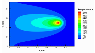 | 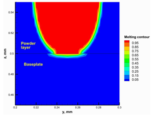 |
| 30 | 150 | 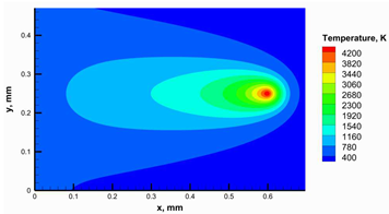 | 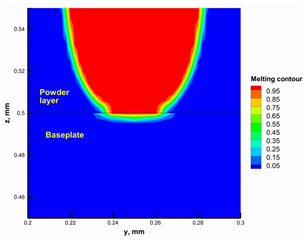 |
| Item | Sample A | Sample B |
|---|---|---|
| Preheating laser power, W | 20 | 30 |
| Melting laser power, W | 150 | 150 |
| Hatching distance, µm | 50 | 50 |
| Layer thickness, µm | 60 | 60 |
Disclaimer/Publisher’s Note: The statements, opinions and data contained in all publications are solely those of the individual author(s) and contributor(s) and not of MDPI and/or the editor(s). MDPI and/or the editor(s) disclaim responsibility for any injury to people or property resulting from any ideas, methods, instructions or products referred to in the content. |
© 2023 by the authors. Licensee MDPI, Basel, Switzerland. This article is an open access article distributed under the terms and conditions of the Creative Commons Attribution (CC BY) license (https://creativecommons.org/licenses/by/4.0/).
Share and Cite
Kaya, D.; Abdelmoula, M.; Küçüktürk, G.; Grossin, D.; Stamboulis, A. A Novel Approach for Powder Bed Fusion of Ceramics Using Two Laser Systems. Materials 2023, 16, 2507. https://doi.org/10.3390/ma16062507
Kaya D, Abdelmoula M, Küçüktürk G, Grossin D, Stamboulis A. A Novel Approach for Powder Bed Fusion of Ceramics Using Two Laser Systems. Materials. 2023; 16(6):2507. https://doi.org/10.3390/ma16062507
Chicago/Turabian StyleKaya, Duran, Mohamed Abdelmoula, Gökhan Küçüktürk, David Grossin, and Artemis Stamboulis. 2023. "A Novel Approach for Powder Bed Fusion of Ceramics Using Two Laser Systems" Materials 16, no. 6: 2507. https://doi.org/10.3390/ma16062507