A New Environmentally Friendly Mortar from Cement, Waste Marble and Nano Iron Slag as Radiation Shielding


Abstract
:1. Introduction
2. Materials and Methods
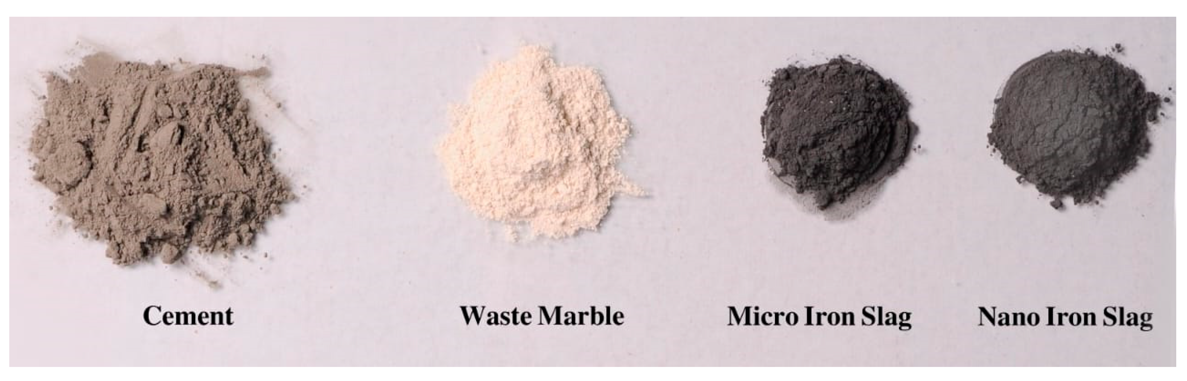
2.1. Materials
2.2. Synthesis of Nano Iron Slag
2.3. Mortar Sample Preparation
2.4. Radiation Measurement Setup
2.5. Theoretical Approach
3. Results and Discussion
3.1. Microstructural Characterization
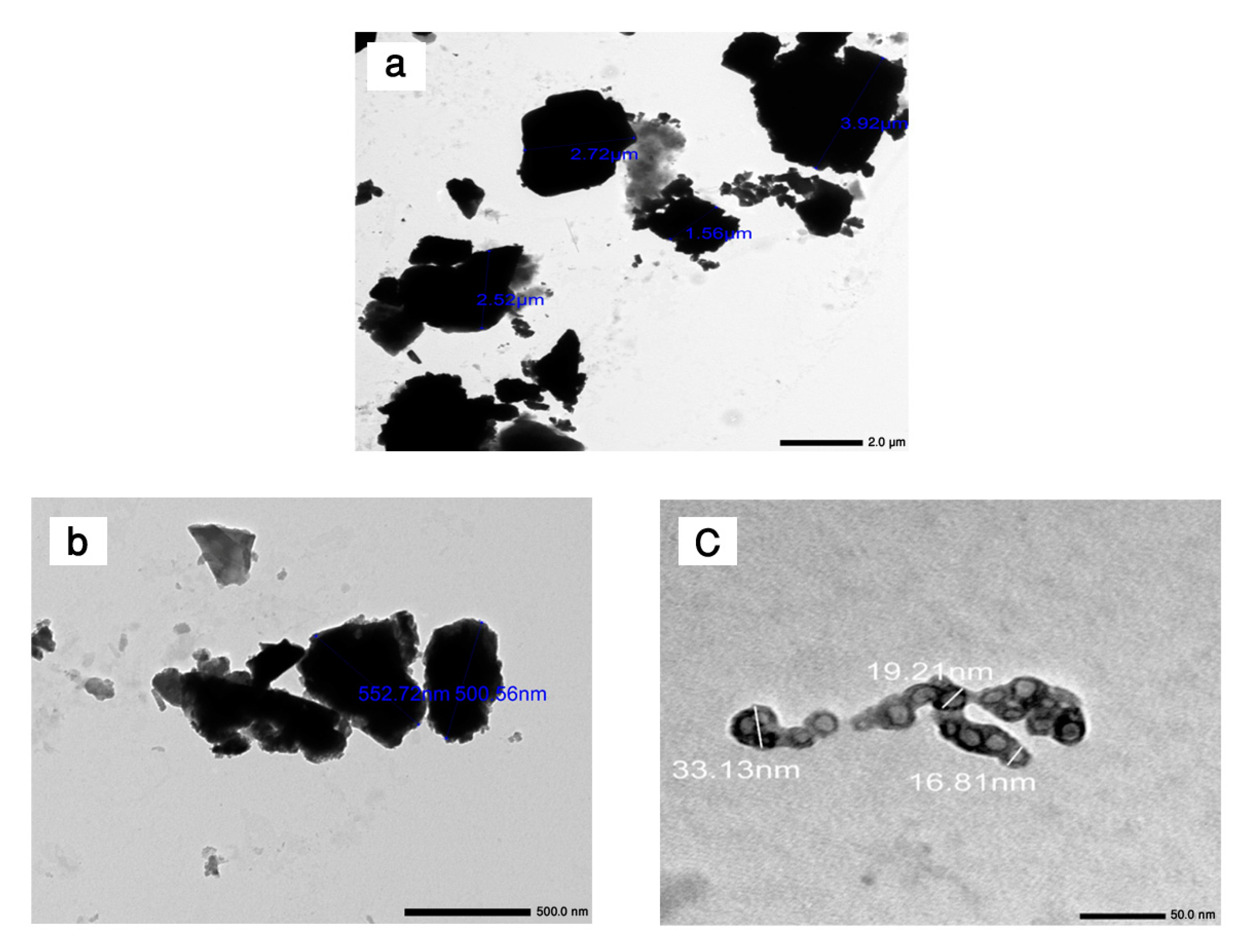
3.1.1. Transmission Electron Microscope (TEM)
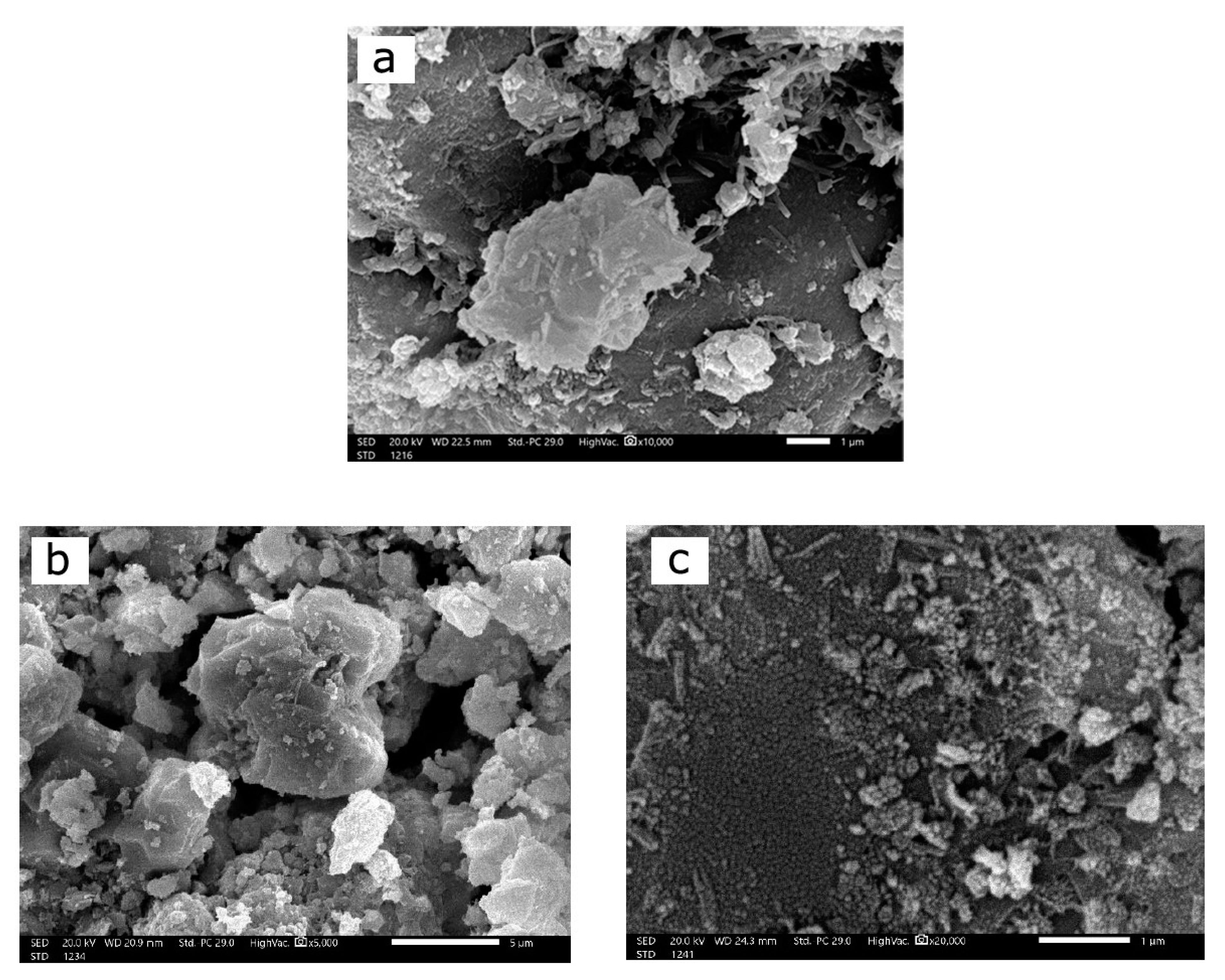
3.1.2. Scanning Electron Microscope (SEM)
3.2. Shielding Parameters
4. Conclusions
Author Contributions
Funding
Institutional Review Board Statement
Informed Consent Statement
Data Availability Statement
Conflicts of Interest
References
- Jaha, N.; Islam, G.M.S.; Kabir, M.F.; Khandaker, M.U.; Bhuian, A.K.M.S.I. Ionizing radiation shielding efficacy of common mortar and concrete used in Bangladeshi dwellings. Case Stud. Constr. Mater. 2022, 17, e01547. [Google Scholar]
- El-Samrah, M.G.; Abdel-Rahman, M.A.E.; El Shazly, R.M. Effect of heating on physical, mechanical, and nuclear radiation shielding properties of modified concrete mixes. Radiat. Phys. Chem. 2018, 153, 104–110. [Google Scholar] [CrossRef]
- Shoag, J.M.; Burns, K.M.; Kahlon, S.S.; Parsons, P.J.; Bijur, P.E.; Taragin, B.H.; Markowitz, M. Lead poisoning risk assessment of radiology workers using lead shields. Arch. Environ. Occup. Health 2020, 75, 60–64. [Google Scholar] [CrossRef]
- Elsafi, M.; Sayyed, M.I.; Almuqrin, A.H.; Gouda, M.M.; El-Khatib, A.M. Analysis of particle size on mass dependent attenuation capability of bulk and nanoparticle PbO radiation shields. Results Phys. 2021, 26, 104458. [Google Scholar] [CrossRef]
- Ara, A.; Usmani, J.A. Lead toxicity: A review. Interdiscip. Toxicol. 2015, 8, 55–64. [Google Scholar]
- Yue, K.; Luo, W.; Dong, X.; Wang, C.; Wu, G.; Jiang, M.; Zha, Y. A new lead-free radiation shielding material for radiotherapy. Radiat. Prot. Dosim. 2009, 133, 256–260. [Google Scholar] [CrossRef] [PubMed]
- Bashter, I.I. Calculation of radiation attenuation coefficients for shielding concretes. Ann. Nucl. Energy 1997, 24, 1389–1401. [Google Scholar] [CrossRef]
- Mahmoud, K.A.; Sayyed, M.I.; Tashlykov, O.L. Gamma ray shielding characteristics and exposure buildup factor for some natural rocks using MCNP-5 code. Nucl. Eng. Technol. 2019, 51, 1835–1841. [Google Scholar] [CrossRef]
- Ouda, A.S. Development of high-performance heavy density concrete using different aggregates for gamma-ray shielding. Prog. Nucl. Energy 2015, 79, 48–55. [Google Scholar] [CrossRef] [Green Version]
- Vu, H.Q.; Tran, V.H.; Nguyen, P.T.; Le, N.T.H.; Le, M.T. Radiation Shielding Properties Prediction of Barite used as Small Aggregate in Mortar. Eng. Technol. Appl. Sci. Res. 2020, 10, 6469–6475. [Google Scholar] [CrossRef]
- Sheriff, K.M.M.; Subramanian, N.; Rahman, S.; Jayaram, J. Integrated optimization model and methodology for plastics recycling: Indian empirical evidence. J. Clean. Prod. 2017, 153, 707–717. [Google Scholar] [CrossRef]
- Çelik, A.İ.; Özkılıç, Y.O.; Zeybek, Ö.; Karalar, M.; Qaidi, S.; Ahmad, J.; Burduhos-Nergis, D.D.; Bejinariu, C. Mechanical Behavior of Crushed Waste Glass as Replacement of Aggregates. Materials 2022, 15, 8093. [Google Scholar] [CrossRef]
- Qaidi, S.; Najm, H.M.; Abed, S.M.; Özkılıç, Y.O.; Al Dughaishi, H.; Alosta, M.; Sabri, M.M.; Alkhatib, F.; Milad, A. Concrete containing waste glass as an environmentally friendly aggregate: A review on fresh and mechanical characteristics. Materials 2022, 15, 6222. [Google Scholar] [CrossRef] [PubMed]
- Beskopylny, A.N.; Shcherban’, E.M.; Stel’makh, S.A.; Meskhi, B.; Shilov, A.A.; Varavka, V.; Evtushenko, A.; Özkılıç, Y.O.; Aksoylu, C.; Karalar, M. Composition Component Influence on Concrete Properties with the Additive of Rubber Tree Seed Shells. Appl. Sci. 2022, 12, 11744. [Google Scholar] [CrossRef]
- Shcherban’, E.M.; Stel’makh, S.A.; Beskopylny, A.N.; Mailyan, L.R.; Meskhi, B.; Shilov, A.A.; Chernil’nik, A.; Özkılıç, Y.O.; Aksoylu, C. Normal-Weight Concrete with Improved Stress--Strain Characteristics Reinforced with Dispersed Coconut Fibers. Appl. Sci. 2022, 12, 11734. [Google Scholar] [CrossRef]
- Karalar, M.; Bilir, T.; Çavuşlu, M.; Özkiliç, Y.O.; Sabri, M.M. Use of recycled coal bottom ash in reinforced concrete beams as replacement for aggregate. Front. Mater. 2022, 9, 1064604. [Google Scholar] [CrossRef]
- Qaidi, S.; Al-Kamaki, Y.; Hakeem, I.; Dulaimi, A.F.; Özkılıç, Y.; Sabri, M.; Sergeev, V. Investigation of the physical-mechanical properties and durability of high-strength concrete with recycled PET as a partial replacement for fine aggregates. Front. Mater. 2023, 10, 1101146. [Google Scholar] [CrossRef]
- Karalar, M.; Özkılıç, Y.O.; Aksoylu, C.; Sabri, M.M.; Beskopylny, A.N.; Stel’Makh, S.A.; Shcherban, E.M. Flexural behavior of reinforced concrete beams using waste marble powder towards application of sustainable concrete. Front. Mater. 2022, 9, 1068791. [Google Scholar] [CrossRef]
- Basaran, B.; Kalkan, I.; Aksoylu, C.; Özkılıç, Y.O.; Sabri, M.M. Effects of Waste Powder, Fine and Coarse Marble Aggregates on Concrete Compressive Strength. Sustainability 2022, 14, 14388. [Google Scholar] [CrossRef]
- Ouda, A.S.; Abdel-Gawwad, H.A. The effect of replacing sand by iron slag on physical, mechanical and radiological properties of cement mortar. HBRC J. 2017, 13, 255–261. [Google Scholar] [CrossRef] [Green Version]
- Kore, S.D.; Vyas, A.K. Impact of marble waste as coarse aggregate on properties of lean cement concrete. Case Stud. Constr. Mater. 2016, 4, 85–92. [Google Scholar]
- Alabsy, M.T.; Gouda, M.M.; Abbas, M.I.; Al-Balawi, S.M.; El-Khatib, A.M. Enhancing the Gamma-Radiation-Shielding Properties of Gypsum—Lime—Waste Marble Mortars by Incorporating Micro-and Nano-PbO Particles. Materials 2023, 16, 1577. [Google Scholar] [CrossRef] [PubMed]
- Hekal, E.E.; Abo-El-Enein, S.A.; El-Korashy, S.A.; Megahed, G.M.; El-Sayed, T.M. Hydration characteristics of Portland cement--Electric arc furnace slag blends. HBRC J. 2013, 9, 118–124. [Google Scholar] [CrossRef] [Green Version]
- Huaiwei, Z.; Xin, H. An overview for the utilization of wastes from stainless steel industries. Resour. Conserv. Recycl. 2011, 55, 745–754. [Google Scholar] [CrossRef]
- Tsakiridis, P.E.; Papadimitriou, G.D.; Tsivilis, S.; Koroneos, C. Utilization of steel slag for Portland cement clinker production. J. Hazard. Mater. 2008, 152, 805–811. [Google Scholar] [CrossRef]
- Xian, W.; Qing-Sheng, C.A.I. Steel slag as an iron fertilizer for corn growth and soil improvement in a pot experiment. Pedosphere 2006, 16, 519–524. [Google Scholar]
- Huijgen, W.J.J.; Witkamp, G.-J.; Comans, R.N.J. Mineral CO2 sequestration by steel slag carbonation. Environ. Sci. Technol. 2005, 39, 9676–9682. [Google Scholar] [CrossRef] [PubMed]
- Ibrahim, A.M.; Mohamed, A.R.; El-Khatib, A.M.; Alabsy, M.T.; Elsalamawy, M. Effect of hematite and iron slag as aggregate replacement on thermal, mechanical, and gamma-radiation shielding properties of concrete. Constr. Build. Mater. 2021, 310, 125225. [Google Scholar] [CrossRef]
- Sayyed, M.I.; Elsafi, M.; Almuqrin, A.H.; Cornish, K.; Elkhatib, A.M. Novel Shielding Mortars for Radiation Source Transportation and Storage. Sustainability 2022, 14, 1248. [Google Scholar] [CrossRef]
- Abd-Elzaher, M.; Badawi, M.S.; El-Khatib, A.; Thabet, A.A. Determination of full energy peak efficiency of NaI (Tl) detector depending on efficiency transfer principle for conversion form experimental values. World J. Nucl. Sci. Technol. 2012, 2, 21242. [Google Scholar] [CrossRef] [Green Version]
- Alabsy, M.T.; Alzahrani, J.S.; Sayyed, M.I.; Abbas, M.I.; Tishkevich, D.I.; El-Khatib, A.M.; Elsafi, M. Gamma-Ray Attenuation and Exposure Buildup Factor of Novel Polymers in Shielding Using Geant4 Simulation. Materials 2021, 14, 5051. [Google Scholar] [CrossRef]
- El-Khatib, A.M.; Abbas, M.I.; Elzaher, M.A.; Badawi, M.S.; Alabsy, M.T.; Alharshan, G.A.; Aloraini, D.A. Gamma Attenuation Coefficients of Nano Cadmium Oxide/High density Polyethylene Composites. Sci. Rep. 2019, 9, 16012. [Google Scholar] [CrossRef] [PubMed] [Green Version]
- Berger, M.J.; Hubbell, J.H.; Seltzer, S.M.; Chang, J.; Coursey, J.S.; Sukumar, R.; Zucker, D.S.; Olsen, K. XCOM: Photon Cross Sections Database. 2010. Available online: http//www.nist.gov/pml/data/xcom (accessed on 15 May 2022).
- El-khatib, A.; Abbas, M.I.; Sayyed, M.I.; Khandaker, M.U.; Abd-Elzaher, M.; Khalil, M.M.; Elsafi, M.; Gouda, M.M. Assessment of γ-radiation shielding behavior of some mixed nature clays. Radiat. Phys. Chem. 2022, 200, 110236. [Google Scholar] [CrossRef]
- Alharshan, G.A.; Aloraini, D.A.; Elzaher, M.A.; Badawi, M.S.; Alabsy, M.T.; Abbas, M.I.; El-Khatib, A.M. A comparative study between nano-cadmium oxide and lead oxide reinforced in high density polyethylene as gamma rays shielding composites. Nucl. Technol. Radiat. Prot. 2020, 35, 42–49. [Google Scholar] [CrossRef]
- El-Khatib, A.M.; Shalaby, T.I.; Antar, A.; Elsafi, M. Improving Gamma Ray Shielding Behaviors of Polypropylene Using PbO Nanoparticles: An Experimental Study. Materials 2022, 15, 3908. [Google Scholar] [CrossRef]
- Abbas, Y.M.; El-Khatib, A.M.; Badawi, M.S.; Alabsy, M.T.; Hagag, O.M. Gamma attenuation through nano lead-nano copper PVC composites. Nucl. Technol. Radiat. Prot. 2021, 36, 50–59. [Google Scholar] [CrossRef]
- Gerward, L.; Guilbert, N.; Jensen, K.B.; Levring, H. WinXCom—A program for calculating X-ray attenuation coefficients. Radiat. Phys. Chem. 2004, 71, 653–654. [Google Scholar] [CrossRef]
- El-Khatib, A.M.; Abbas, Y.M.; Badawi, M.S.; Hagag, O.M.; Alabsy, M.T. Gamma radiation shielding properties of recycled polyvinyl chloride composites reinforced with micro/nano-structured PbO and CuO particles. Phys. Scr. 2021, 96, 125316. [Google Scholar] [CrossRef]


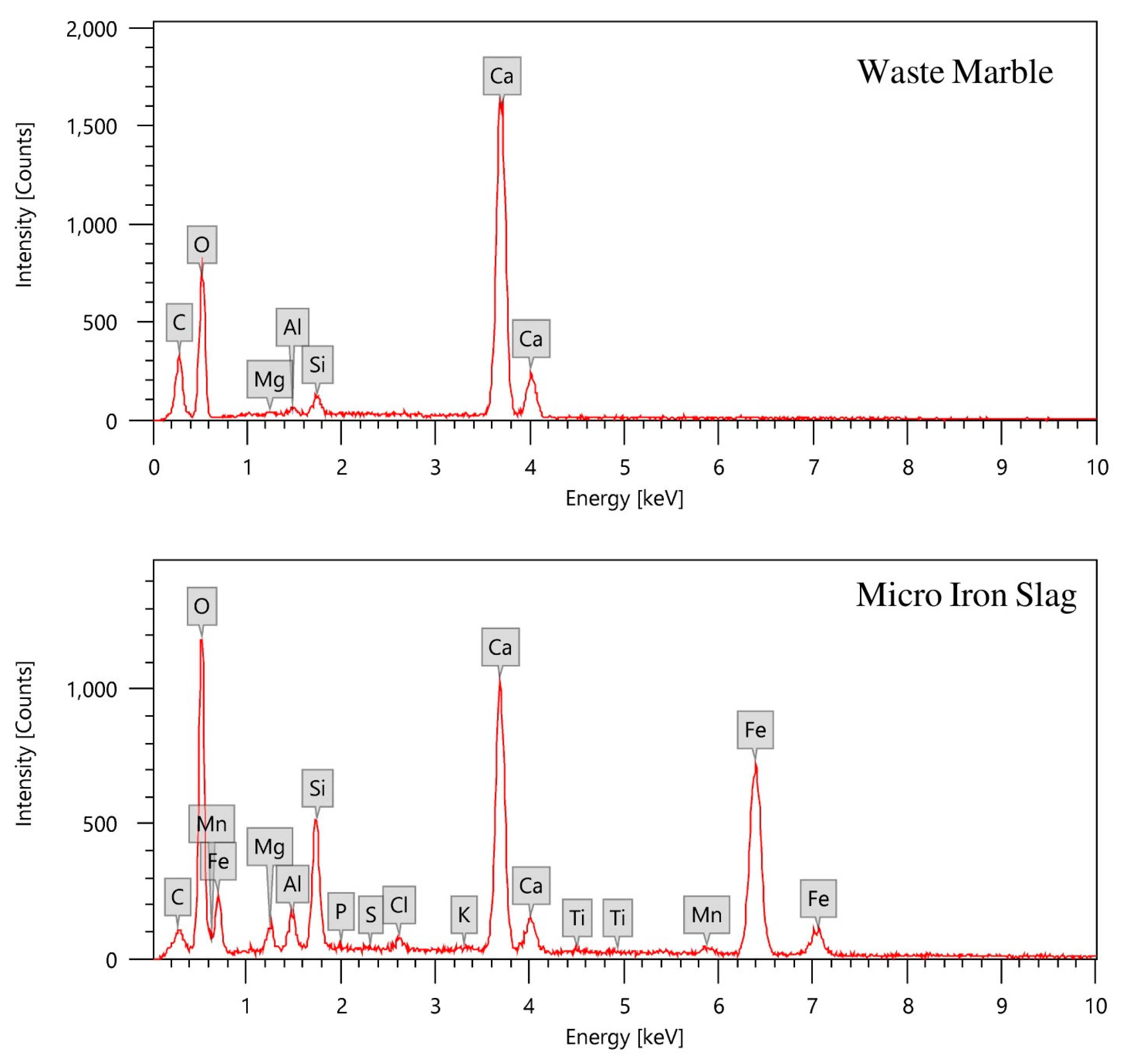
| Element | Chemical Composition (wt.%) | ||
|---|---|---|---|
| Cement | Waste Marble | Iron Slag | |
| C | 11.54 | 2.53 | |
| O | 36.45 | 53.15 | 39.57 |
| Mg | 1.51 | 0.21 | 1.39 |
| Al | 2.38 | 0.36 | 1.59 |
| Si | 9.86 | 0.70 | 5.47 |
| P | - | - | 0.08 |
| S | 1.94 | - | 0.07 |
| Cl | - | - | 0.53 |
| K | - | 0.07 | |
| Ca | 45.13 | 34.04 | 17.03 |
| Ti | - | - | 0.20 |
| Mn | - | - | 0.74 |
| Fe | 2.73 | - | 30.73 |
| Sample Codes | Composition | Density (g/cm3) | ||||
|---|---|---|---|---|---|---|
| Cement | Aggregate | Water | ||||
| Waste Marble | Micro-IS | Nano-IS | ||||
| CM-Ctrl | 1 | 3 | - | - | 0.5 | 2.109 |
| CM-MIS | 1 | 2 | 1 | - | 2.597 | |
| CM-NIS | 1 | 2 | - | 1 | 2.635 | |
| Source | Photon Energy (keV) |
|---|---|
| Am-241 | 59.53 |
| Ba-133 | 80.99 |
| 356.01 | |
| Cs-137 | 661.66 |
| Co-60 | 1173.23 |
| 1332.50 | |
| Eu-152 | 121.78 |
| 244.69 | |
| 778.90 | |
| 964.13 | |
| 1408.01 |
| Photon Energy (keV) | Linear Attenuation Coefficient μ (cm−1) | ||||
|---|---|---|---|---|---|
| CM-Ctrl | CM-MIS | CM-NIS | Ordinary Mortar [7] | Lead | |
| 59.53 | 0.5972 | 0.9351 | 1.1244 | 0.5158 | 52.45 |
| 80.99 | 0.4244 | 0.5848 | 0.7024 | 0.3849 | 23.19 |
| 121.78 | 0.3182 | 0.4219 | 0.5052 | 0.3099 | 36.60 |
| 244.69 | 0.2394 | 0.2955 | 0.3519 | 0.2407 | 6.60 |
| 356.01 | 0.2132 | 0.2609 | 0.3088 | 0.2092 | 3.011 |
| 661.66 | 0.1599 | 0.1972 | 0.2319 | 0.1617 | 1.173 |
| 778.90 | 0.1525 | 0.1864 | 0.2196 | 0.1502 | 0.9801 |
| 964.13 | 0.1375 | 0.1651 | 0.1927 | 0.1358 | 0.7968 |
| 1173.23 | 0.1217 | 0.1546 | 0.1783 | 0.1232 | 0.6755 |
| 1332.50 | 0.1175 | 0.1391 | 0.1601 | 0.1155 | 0.6172 |
| 1408.01 | 0.1112 | 0.1368 | 0.1566 | 0.1123 | 0.5971 |
| E (keV) | (μCM-NIS − μCM-Ctrl)/μCM-Ctrl % | (μCM-NIS − μOM)/μOM % |
|---|---|---|
| 59.53 | 88.28 | 117.991 |
| 80.99 | 65.50 | 82.489 |
| 121.78 | 58.77 | 63.020 |
| 244.69 | 46.99 | 46.199 |
| 356.01 | 44.84 | 47.610 |
| 661.66 | 45.03 | 43.414 |
| 778.90 | 44.00 | 46.205 |
| 964.13 | 40.15 | 41.900 |
| 1173.23 | 46.51 | 44.724 |
| 1332.50 | 36.26 | 38.615 |
| 1408.01 | 40.83 | 39.448 |
| E (keV) | Mass Attenuation Coefficient (cm2/g) | ||||||
|---|---|---|---|---|---|---|---|
| CM-Ctrl | CM-MIS | CM-NIS | |||||
| Exp. | XCOM | Δ % | Exp. | XCOM | Δ % | Exp. | |
| 59.53 | 0.2832 | 0.2864 | −1.13% | 0.3601 | 0.3648 | −1.30% | 0.4267 |
| 80.99 | 0.2012 | 0.1997 | 0.77% | 0.2252 | 0.2294 | −1.84% | 0.2666 |
| 121.78 | 0.1509 | 0.1524 | −1.00% | 0.1625 | 0.1601 | 1.47% | 0.1917 |
| 244.69 | 0.1135 | 0.1152 | −1.46% | 0.1138 | 0.1155 | −1.48% | 0.1335 |
| 356.01 | 0.1011 | 0.0999 | 1.22% | 0.1005 | 0.0996 | 0.88% | 0.1172 |
| 661.66 | 0.0758 | 0.0771 | −1.62% | 0.0759 | 0.0767 | −0.99% | 0.088 |
| 778.9 | 0.0723 | 0.0716 | 1.03% | 0.0718 | 0.0712 | 0.81% | 0.0833 |
| 964.13 | 0.0652 | 0.0647 | 0.77% | 0.0636 | 0.0644 | −1.22% | 0.0731 |
| 1173.23 | 0.0577 | 0.0587 | −1.73% | 0.0595 | 0.0584 | 1.94% | 0.0677 |
| 1332.50 | 0.0557 | 0.0550 | 1.22% | 0.0536 | 0.0548 | −2.17% | 0.0608 |
| 1408.01 | 0.0527 | 0.0535 | −1.46% | 0.0527 | 0.0532 | −1.04% | 0.0594 |
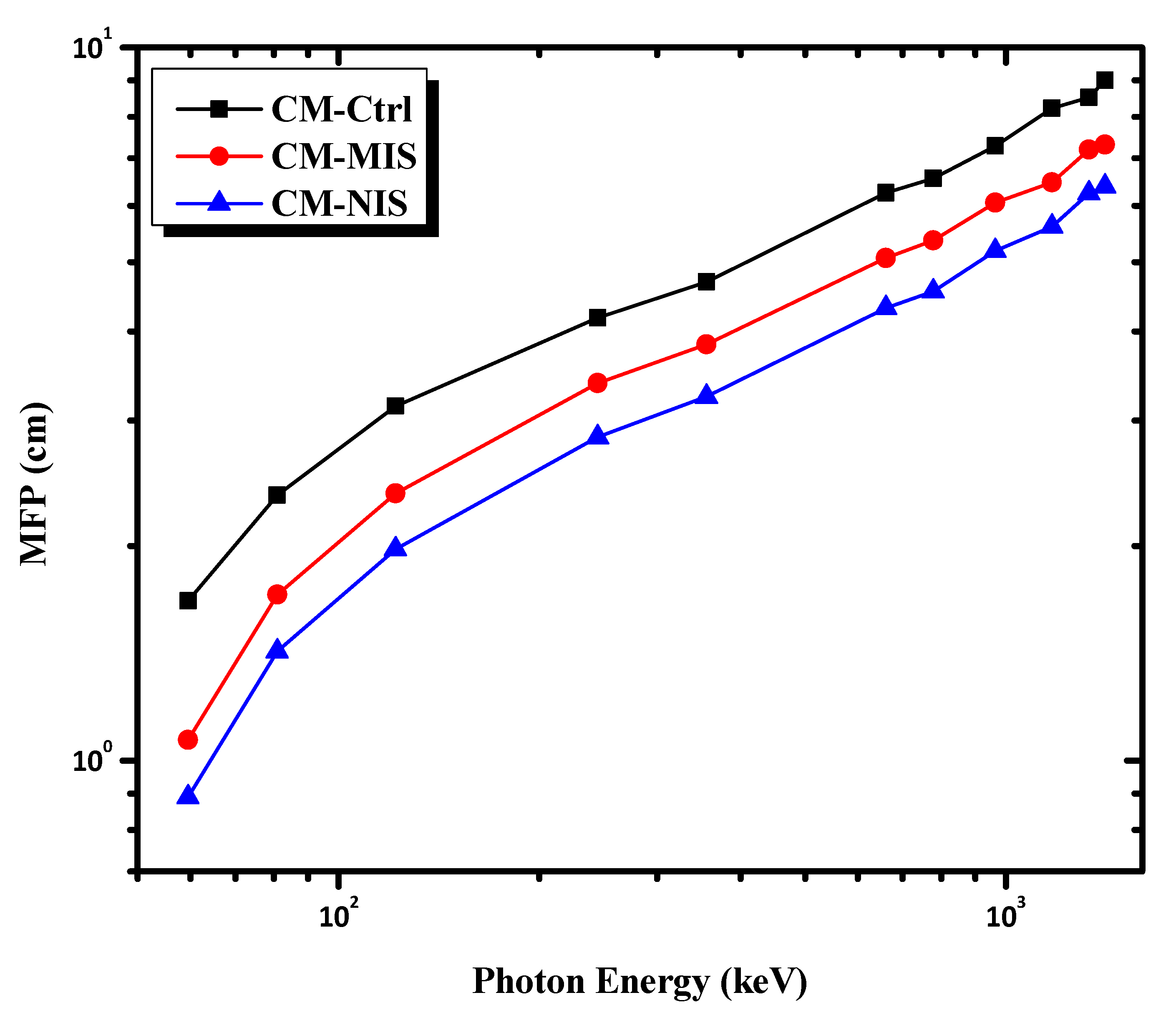
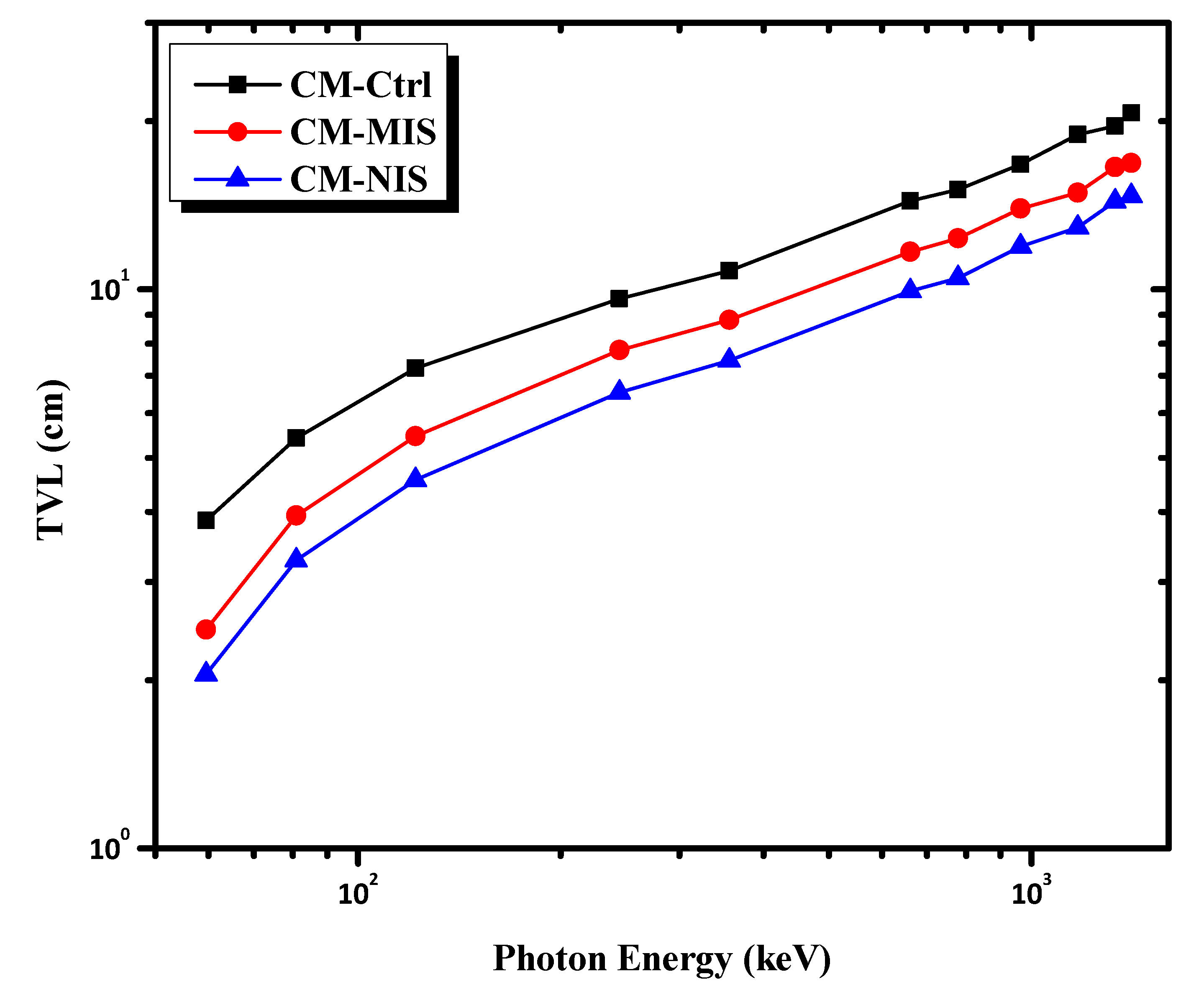
| E (keV) | CM-Ctrl | CM-MIS | CM-NIS | Lead | ||||||
|---|---|---|---|---|---|---|---|---|---|---|
| HVL (cm) | TVL (cm) | MFP (cm) | HVL (cm) | TVL (cm) | MFP (cm) | HVL (cm) | TVL (cm) | MFP (cm) | HVL (cm) | |
| 59.53 | 1.161 | 3.856 | 1.674 | 0.741 | 2.462 | 1.069 | 0.616 | 2.048 | 0.889 | 0.013 |
| 80.99 | 1.633 | 5.426 | 2.356 | 1.185 | 3.937 | 1.710 | 0.987 | 3.278 | 1.424 | 0.030 |
| 121.78 | 2.178 | 7.236 | 3.143 | 1.643 | 5.458 | 2.370 | 1.372 | 4.558 | 1.979 | 0.019 |
| 244.69 | 2.895 | 9.618 | 4.177 | 2.346 | 7.792 | 3.384 | 1.970 | 6.543 | 2.842 | 0.105 |
| 356.01 | 3.251 | 10.800 | 4.690 | 2.657 | 8.826 | 3.833 | 2.245 | 7.457 | 3.238 | 0.230 |
| 661.66 | 4.335 | 14.400 | 6.254 | 3.515 | 11.676 | 5.071 | 2.989 | 9.929 | 4.312 | 0.591 |
| 778.90 | 4.545 | 15.099 | 6.557 | 3.719 | 12.353 | 5.365 | 3.156 | 10.485 | 4.554 | 0.707 |
| 964.13 | 5.041 | 16.746 | 7.273 | 4.198 | 13.947 | 6.057 | 3.597 | 11.949 | 5.189 | 0.870 |
| 1173.23 | 5.696 | 18.920 | 8.217 | 4.483 | 14.894 | 6.468 | 3.888 | 12.914 | 5.609 | 1.026 |
| 1332.50 | 5.899 | 19.596 | 8.511 | 4.983 | 16.553 | 7.189 | 4.329 | 14.382 | 6.246 | 1.123 |
| 1408.01 | 6.233 | 20.707 | 8.993 | 5.067 | 16.832 | 7.310 | 4.426 | 14.704 | 6.386 | 1.161 |
| E (keV) | HVLCM-NIS (cm) | HVLLead (cm) | Effective Mortar Thickness Equivalent to 1 mm Lead |
|---|---|---|---|
| 59.53 | 0.616 | 0.013 | 46.65 |
| 80.99 | 0.987 | 0.030 | 33.02 |
| 121.78 | 1.372 | 0.019 | 72.46 |
| 244.69 | 1.970 | 0.105 | 18.77 |
| 356.01 | 2.245 | 0.230 | 9.75 |
| 661.66 | 2.989 | 0.591 | 5.06 |
| 778.90 | 3.156 | 0.707 | 4.46 |
| 964.13 | 3.597 | 0.870 | 4.14 |
| 1173.23 | 3.888 | 1.026 | 3.79 |
| 1332.50 | 4.329 | 1.123 | 3.86 |
| 1408.01 | 4.426 | 1.161 | 3.81 |
Disclaimer/Publisher’s Note: The statements, opinions and data contained in all publications are solely those of the individual author(s) and contributor(s) and not of MDPI and/or the editor(s). MDPI and/or the editor(s) disclaim responsibility for any injury to people or property resulting from any ideas, methods, instructions or products referred to in the content. |
© 2023 by the authors. Licensee MDPI, Basel, Switzerland. This article is an open access article distributed under the terms and conditions of the Creative Commons Attribution (CC BY) license (https://creativecommons.org/licenses/by/4.0/).
Share and Cite
El-Khatib, A.M.; Abbas, M.I.; Elzaher, M.A.; Anas, M.; El Moniem, M.S.A.; Montasar, M.; Ellithy, E.; Alabsy, M.T. A New Environmentally Friendly Mortar from Cement, Waste Marble and Nano Iron Slag as Radiation Shielding. Materials 2023, 16, 2541. https://doi.org/10.3390/ma16072541
El-Khatib AM, Abbas MI, Elzaher MA, Anas M, El Moniem MSA, Montasar M, Ellithy E, Alabsy MT. A New Environmentally Friendly Mortar from Cement, Waste Marble and Nano Iron Slag as Radiation Shielding. Materials. 2023; 16(7):2541. https://doi.org/10.3390/ma16072541
Chicago/Turabian StyleEl-Khatib, Ahmed M., Mahmoud I. Abbas, Mohamed Abd Elzaher, M. Anas, Mohamed S. Abd El Moniem, Mahmoud Montasar, Ebeid Ellithy, and Mahmoud T. Alabsy. 2023. "A New Environmentally Friendly Mortar from Cement, Waste Marble and Nano Iron Slag as Radiation Shielding" Materials 16, no. 7: 2541. https://doi.org/10.3390/ma16072541